Note: Descriptions are shown in the official language in which they were submitted.
2089~1
Container
The present invention relates to containers.
A conventional form of stacking and nesting
container comprises two bail srms~ stacking bars or
support bar~ pivotally attached to and extending between
the sides of the container, usually at opposing ends of
the container. Each bail arm can be moved from a fitorage
(or nesting) position to a position in which it can
support a second like container stacked on top of a first
container. When the bail arms ~re in the storsge
positions, they do not obstruct a second container, which
can therefore nest in the container below. However, such
bail arms can sDmetimes result in inefficient u o of the
capacity of the containers, because the fixed volune
defined between the bases of two stacked containers is
only efficiently used when the containers are full to the
height between the bases.
It is an object of the present invention to obviate
or mitigate these disadvantages.
According to the present invention there is
provided a container comprising e support member
mountable on the container et a stacking position in
which a second contsiner may be rested on the support
member to form a stsck, the support member being
20~521
movable between any of a plurality of stacking positions
as aforesaid to support a second container at respective
positions above the container base.
At the stacking positions, the support member
preferably supports a second container st respective
heights above the container bsse. Preferably the support
member also has a nesting position in which the support
member allows a second like container to be nested in the
container. There may be at least two vertically sligned
stacking positions.
The container may comprise mounting means operable
to mount the support member on the container and so
arranged as to sllow the support member to move as
sforessid.
The mounting means may include a projection which
is confined, in use, to a predetermined range of
locations to limit the range of movement of the support
means. The projection may be confined by surfaces which
do not continuously bound the region in which the
projection is confined.
Preferably the mounting means allow the support
member to pivot relative to the rest of the conteiner,
2 ~ ~3 9 ~ 2 ~ .
-- 3
whereby the fiupport member may be pivotted snd moved
between any of the plurality of stacking positions. The
mounting means may allow the pivot axis to move, for
instance relative to the container ur relative to the
support member.
The mounting means may be so formed as to tend to
resist movement of the pivot axis when the support member
is in at least one of the positions, whereby the number
of the said positions accessible by the support member is
restricted unless the resistance is overcome. The
support member can preferably only move between a first
stacking position and a nesting position unless the
resistance is overcome. The first fitacking position may
be the uppermost stacking position. The resistance may
be provided by a resilient detent formation which must be
moved against its associsted resilience to allow the
pivot exis to pass.
Preferably the conteiner incorporates a surface
which is so oriented as to urge the pivot axis to move to
a preferred position relative to the container, when the
support member is in one of the said positions.
Preferably the said one pofiition is the nesting position.
Preferably the said surface is provided by a wall of the
container. The surface and the support ~ember may be so
2089~21
- 4 -
formed 88 to require the pivot axis to have a pre-set
position when the support member is in the said one
position. The pre-set position may correspond with the
nesting position.
The mounting means may be so formed as to allow the
pivot axis to be moved while the support member is in the
resting position, to a position corresponding to a
selected stacking position and st which the support
member may swing from the nesting position to the
selected stacking position without further movement of
the pivot axis.
Preferably, the mounting means comprise a slot,
which is preferably arcuate, the pivot axis being movable
along the slot. If the slot is arcuate, it is preferably
centred at the nesting position. The slot may be formed
in a container wall. Alternatively, there may be a pivot
member fixed in relation to the container wall, and
located in a slot which is movable with the support
member. Preferably the mounting means incorporates a
resilient detent formation so located as to bear on a
part moving along the slot. The detent formation may be
formed in a wall of the slot. The resilience may be
provided by the msterial of the wall of the slot.
208952~ `.
Preferably the support member comprises at least
one first portion locatable in the slot of the mounting
means to be pivotable within and movable along the slot,
and a second portion which extends acro~s the container
to support a second like container when in the stacking
position. The support member may further comprise one or
more connecting portions to connect the second portion to
the or each first portion. The support member is
preferably fiubstantially U-shaped, and may be comprised
of metal and/or reinforced plastics material or other
suitable material.
Preferably corresponding mounting means are
provided at opposite walls of the container.
Preferably, the container is adapted to retain the
support member in each of the stacking positions. The
container may comprise a formation at each stacking
position, each formation being so formed es to retain the
support member in the corresponding stacking position.
Each formation may comprise a notch in which the support
member may rest. The support member may comprise e
projection which enhances engagement between the support
member and the retaining formation. The formations ere
preferably formed in ide walls of the container.
2~8~2~
Preferably, a channel forming member is provided
adjacent the side w8118 of the container, to form a
generally open-topped channel. The mounting means may be
provided in one or both channel walls. The mounting
means may comprise a slot in one or both channel walls,
and corresponding portions of the support member
locatable in the slot or slots.
Preferably a plurality of support members are
provided. Preferably two support members are located
toward respective ends of the container, each being
mounted as aforesaid.
The container preferably has a base and walls
extending above the base.
Embodiments of the present invention will now be
described in more detail, by way of example only, and
with reference to the accompanying drawings, in which:
Fig. 1 is a diagrammatic fiide elevation of part of
one end of a container according to the present
invention, showing a support member in three alternative
positions;
Fig. 2 is a diegrammatic cross-section of a first
2~9521
-- 7
type of pivotal connection viewed along the line Il-II in
Fig. 1 with details of the end wall omitted, for clarity;
Fig. 3 iB a fiimilar diagrammatic cross-section of a
second type of pivotal connection;
Fig. 4 is a fiimilar disgrammatic cross-section of a
third type of pivotal connection;
Fig. 5 is an elevation of the container wall
corresponding to Fig. 1, viewed from inside the container
along the line V-V of Fig. 4, and showing the use of the
pivotal connection of Fig. 4;
Fig. 6 is an elevation corresponding to Fig. 5,
showing a further type of pivotal connection;
Fig. 7 is a side view corresponding to Fig. 1,
showing a second embodiment;
Fig. 8 is a partial plan view, in section, along
the line 8-8 of Fig. 7, with parts cut away; snd
Fig. 9 is a side view showing a third embodiment
and corresponding to Fig. ~, but showing the opposite end
of the container.
208952~
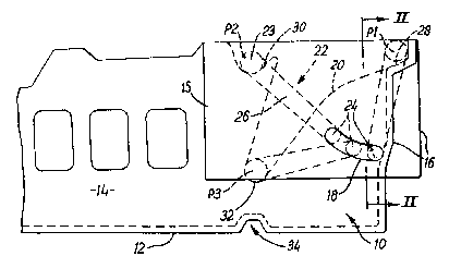
Turning to Fig. 1, a contsiner 10 comprises ~ bsse
12 and four upstanding walls of which part of a side wall
14 and an end wall 16 can be seen in Fig. 1. The wàlls
are formed to allow containers to nest inside each other,
subject to the location of support members, as will be
described. Both side walls 14 comprise an outer channel
forming member 15 (see particularly Figs. 2 and 3~
extending adjacent thereto, to form an upwardly open
channel 17. Alternatively, the channel and channel
forming member could be adjacent the inner face of the
wall 14. Corresponding slots 18 are provided in the
channel 17 in each member 15. The slots 1B are shown as
arcuate, but may be straight. Fig. 2 shows the slot 18
formed in the channel forming member 15. Alternstively,
the slot 18 may be formed at the corresponding height in
the channel forming portion 20 of the side wall 14. In a
further elternative (Fig. 3) a slot 18 is formed in the
channel forming member 15 and also in the wall portion
20.
A support member 22 is provided which comprises a
support bar 23 which extends across the upper mouth of
the container 10, between the side walls 14, and which
further comprises an end portion 24 at each end thereof.
The end portions 24 are locsted within corresponding
slots 18. Connecting portions 26 connect the respecti~e
2~89~21
ends of the support bar 23 to the respective end portions
24, such that the support member 22 is generally U-shaped
(generally inverted when in position in the container).
The support member 22 may be of metal, or reinforced
plastics material, or other suitable material having
adequate strength.
The location of the end portions 24 in the slots 18
~erves to mount the members 22 on the container and
allows the members 22 to pivot about the axis of the end
portions 24 (parallel to the bar 23). The end portions
24 may also slide along the slots 18 to 00ve the pivot
axis relative to the container.
Oorresponding sets of recesses 28,30,32 are formed
in the walls 14 of the container. A recess 28 is formed
at the top of each end wall 16 and recesses (or notches)
30,32 are formed in the channel forming portion 20 of
each side wall 14. The recesses 28,30,32 are so formed
as to be able to engage the support bar 23, to support
the support bar 23 at a fixed position and pre-determined
height above the base 12.
The other end of the container (not shown, but to
the left as viewed in Fig. 1) has a corresponding support
bar arrangement.
20~952~ `
- 10 -
In use, when a similar conteiner is to be nested in
the container 10, each support member 22 is in position
P1, with each support bar 23 in the respective recess 28,
adjacent the respective end wall 16. The end portions 24
are at the lower ends of the slots 18. They will tend to
adopt this position by the influence of gravity. In this
position, the support bars 23 do not obstruct the entry
of the base of a similar container into the container 10,
and therefore allow the similar container to be nested
with the container 10.
When a 6imilar container is to be stacked on top of
the container 10 at a relatively large height above the
base 12 (that is, the containers are to be stacked
relatively far apart), then the support members 22 are
moved from position P1 to position P2 wherein the support
bars 23 are located in the respective recesses 30. It
can be seen that in order for each bar 23 to be located
in the respective recess 30, the support member 22 must
be both pivotted about the end portions 24 and the end
portions 24 moved along the slots 18. When in position
P2, the support bars 23 extend across the container to
provide a support for the base of a similar container
thereby &upporting the similar container at a relatively
lsrge height sbove the base 12. The container 10 may
have e stacking notch 74 in its base, to locate securely
2~9~21
- 11 -
on a support bsr 23 below.
If the vertical distance between stacked containers
i8 desired to be relatively small, then the support
members 22 can be moved to position P3, in which the
respective support bar~ 23 rest in the respective
recesses 32. Again, moving the members 22 into this
position (either from position P1 or P2) requires a
combination of pivotal movement of the members 22 about
the portions 24 snd movement along the slots 18.
Movement between the nesting position P1 and the
various stacking positions is facilitated by having the
slot 1B arcuate and centred on the axis of the bar 23
when et the nesting position P1. A stacking position can
then be selected by pivotting the portions 26 about the
bar 23, to move the portions 24 along the slot 18 to a
position which allows pivotting about the portions 24 to
swing the bar 23 into notch 30 or 32.
The final positions of the bar 23 in the notches
30,32 are vertically aligned, but alternatively could be
vertically offset. A number of positions, some
vertically aligned and some offset, could be provided.
It is to be appreciated that any suitable number of
.
2~9~21
- 12 -
recesses can be provided according to the number of
different stacking heights required. It should also be
understood that the Figures indicate support members
occupying each of the positionfi P1,P2,P3 simultaneously,
whereas, of course, only one position would be in use at
any time.
Another alternative arrangement for mounting the
support bar 23 on the container i8 illustrated in figs. 4
and 5. In this arrangement, a fixed lug or pin 40 is
mounted on or formed integrally with the container wall.
The connecting portion 26 has en elongate slot 42 in
which the lug 40 is located. The lug and slot provide a
pivotal connection between the support member 2~ and the
container 10. Movement of the lug 40 along the slot 42,
as will be described, allows the pivot axis to move
relative to the support member. Small resilient fingers
44 may be formed in the walls of the slot 42 to resist
movement of the lug 40 along the slot 42 unless the
resilience is overcome. In order to allow the resilience
to be overcome, the fingers 44 may be inherently
resilient, or the material in which the slot i8 formed
may be resilient, or both.
Preferably the fingers 44 confine the lug 40 to one
end (the lower end) of the slot 42~ If the resilience is
20S9521
- 13 -
not overcome, the support member 23 ifi then free ta swing
between the nesting position P1 and the uppermost
stscking position P2 at which the support member 23 rests
in a hooked notch 46 to be retained in position.
Fig. 5 shows two other positions P3 and P4 which
are lower stacking positions snd are shown vertically
aligned with position P2 but could be ~rranged in other
ways. A support bar 23 can be placed in positions P3 or
P4 in the following manner. The bar 23 is first swung
out from position P1 or position P2 to sn intermediate
position snd a downward force is spplied to overcome the
resilience in the slot 42 until the lug 4û clears the
fingers 44 and is located above them in the slot. By
sliding the connecting portion 26 up or down on the lug
40, and by pivotting the support bar 23 and connecting
portion 26 about the lug 40, the support bar 23 can be
moved to position P3 or P4. Thus, the support bar 23 can
be moved between any of the positions P1, P2, P3 and P4
by appropriate pivotal movement about the lug 40, and
movement of the pivot axis relative to the support bsr 23
along the slot 42.
For some spplicstions, it may be desirable to
provide more resilient fingers at other positions, or to
provide no resilient fingers.
2~9.~
_ 14 -
Fig. 6 ahows a further alternative arrangement for
mounting the ~upport bar 23 on the container 10. The
illustrated arrangement provides three stacking positions
P2,P3,P4 at different heights. A hook formation 46A is
provided at each fitacking position to receive the bar 23.
~or convenience of description, a support bar 23 and
connecting portion 26 are shown in each of the three
stack5ng positions and at the nesting position but
naturally, only one position would be occupied at any
one time.
In this arrangement, each connecting portion 26
carries a land 50. The container walls carry lands 52.
If the support bar 23 is moved to certain positions
relative to the container 10, the land 50 will contact
one or other of the lands 52, thereby preventing further
movement. In other positions, the connecting portion 26
will engage the container end wall 16 as can be seen at
54. The shape and position of the lands 52 and the land
50 are choosen to confine the land 50 during normal use
to a region 56 between the lands 52 and the end wall 16.
Alternatively, a ring of lands 52 could be used to
confine the land 50 and avoid the need for any contact
with the wall 16 to assist in the confinement. It is to
be noted that the region 56 is not delimited by a
continuous wall. Alternatively, a continuous wall could
2 ~ 2 1
- t5 -
be used. The positions of the lsnds 50,52 could be
reversed, so thst a lsnd or other projection fixed on a
container w811 is confined in a region de~ined relative
to the connecting portion 26. The effect of the
confinement of the land 50 limits the land 50 to a
predetermined range of locations. Since the land 50
moves with the support bar 23, the support bar 23 is
therefore also limited in its range of movement. This
allows the support bar 23 to move between ~tacking
positions (and a nesting position, if one is provided)
but retains the support bar 23 loosely mounted on the
container. In effect, while the slots of figs. 2,3 and 4
allow the corresponding pivot axis to move along a llne,
the confinement in the region 56 allows the pivot axis to
move in two dimensions around the region 56. Thus, while
the connecting member 26 is more loosely mounted on the
container in Fig. 6, it is nevertheless mounted to allow
the support bar to move between stacking positions by a
combination (possibly a complicated combination) of
linear and pivotal movement.
A second embodiment i6 shown in Figs. 7 and B.
This embodiment corresponds closely with the first
embodiment described above, particularly that shown in
Figs. 1 to 3, and corresponding numerals are used, where
applicable. However, the connecting portions 26 are
2 ~ ~ ~ .i 2 1
- 16 -
areuate rather than straight. The end wall 16 slopes
le88 steeply in the region indicated by numeral 100. The
sliding pivot mounting of the connecting portions 26
incorporates a detent, as will be described. Thefie
differences will now be described in more detail.
The connecting portions 26 and the wall region 100
are formed so that the connecting portions 26 lie along
the wall portion 10û when the support member 22 is in the
nesting position P1. In this position, the curve on the
connecting portions 26 places the end portions 24 at or
near the upper end of the slots 1B. This position
corresponds to the position at which the support member
22 can swing (without the pivot axis moving along the
slot) between the nesting position and the uppermost
stacking position P2. These two positions are likely to
be the most frequently used, and correspond to the
nesting and stacking positions of conventional nest/stack
containers.
The mounting arrangement of the support members 26
tends to resist movement of the end portions 24 along the
slots 18, sway from this upper position. The resistance
is provided by a resilient detent formation 102, shown
MoSt clesrly in Fig. 8. The loc~tion of the formation
102 is indiceted in Fig. 7 by a pair of broken lines.
_ 17 -
The formation 102 i8 a prominence formed in the rear wall
20 of the 810t 18. Alternatively, the formation could be
flush with the rear wall 20, the end portion 24 moving
normally in a groove to either side of the formation 102.
Other detent arrangements could be used, and appropriate
resilience can be provided in various ways~
The formation 102 provides resilient resistance to
movement of the end portion 24, which can only move along
the slot 18 past the formation 102 if the resilience is
overcome, for instance by flexing the material of the
rear wall 20 and/or the channel forming member 15.
The presence of the formation 102 tends to retain
the end portion 24 to one side or the other of the
formation 102. In many applications, it is expected that
the end portion 24 will normally be located between the
formation 102 and the upper end of the slot 18, in the
position corresponding to the nesting position P1 and the
upper stacking position P2. The support member 22 can be
moved easily from the nesting position to the upper
stacking position and back, while the end portion 24 is
retained at the corresponding position by the formation
102. It is to be noted that the geometry is such that
forces applied to the support member 22 when in the
stacking position P2 or the nesting position P1, cannot
2089~21
- 18 -
force the end portion 24 past the formation 1D2. This is
a result in particular of the abutment of the connecting
portions 26 and the wall section 100, together with the
curvature of the connecting portions 26.
The security of the arrangement at the positions
P2,P3 can be enhanced by deepening the notches in
relation to Fig. 1, as shown, and providing projections
104 which engage the deepened notches.
If it is required to place the support member 22 in
the lower stacking position P3, the support member 22
should be moved by hand to an intermediate position
between the nesting position and the upper stacking
position, st which position a downward force can be
applied to force the end portions 24 past the formations
102, against the resilience of the wall 20. ûnce the end
portion 24 has been forced past the formation 102, the
location of the pivot axis of the support member 22
changes, as has been described ~bove in relation to Figs.
1 to 6, snd the support member 22 can then be pivotted
down to the lower ~tacking position P3. If it is desired
to return the support member 22 to the upper stacking
position or to the nesting position, the support member
22 is again raised to the intermediate, substantially
upright position snd an upwsrd force is spplied to pull
2 0 8 9 5 2 i
the end portions 24 past the formations 102 to the upper
positions corresponding to the nesting position and the
upper stacking position. Alternatively, this upward
force can be provided by a form of camming action in
which the support member 22 is swung from the lower
stacking position toward the nesting position, until
bearing against the wall section 100. A sideways force,
such as by placing a second container down into the mouth
of the container, or applied by hand, would then force
the support bar 23 outwardly and force the connecting
portions 26 against the wall section 100, thereby
exerting an upward force on the end portions 24, by
virtue o~ a form of camming or levering action. This
would force the end portions 24 past the formations 102.
A further embodiment is shown in Fig. 9. This
embodiment corresponds closely to the embodiment of Figs.
7 and 8 and again has many features in common with the
first embodiment described ebove, particularly in
relation to Figs. 1 to 3. Corresponding numerals are
therefore used. The embodiment of Fig. 9 again
incorporates a detent formation at 102 to resist movement
of the end portions 24 from the positions corresponding
to the nesting position Pl and upper stacking position P2
of the support ~ember 22.
2 0 8 ~
- 20 -
The lower stacking position P3 of the embodiment of
Fig. 9 ifi much lower than the corresponding position in
Fig. 7 snd is not in vertical alignment with the upper
stacking position P2. These two differences csuse a
consequent modification in the shape of the slot 1a below
the detent formation 102. In Fig. 9, in common with
other embodiments described above, the connecting
portions 26 reach down to the lower stacking position in
wall recesses which open into the inside of the
container. These recesses sre sufficiently deep to act
8S the notches 32, and are formed by outwardly projecting
wall portions 106. Because the lowest stacking position
is so low, the lowest projection on the side wall of the
container is therefore et the location indicated by the
numeral 108, slightly below the lower starking position
P3. Normally, a container of this nature stacks by
locating the lowest projection at the upper edge of the
side wall of a container below. If that were to occur
with the contsiner of ~ig. 9, only a relatively small
part (less than one half) of the conteiner would in fact
nest in the contsiner below. The compsctness of e set of
nested containers (the nest factor) can be increased by
further projecting the wall outwardly, in the shaded
region et 110. This provides e region which can receive
the region at 1û8 of e similar container, below the top
edge of the side wall. Conse4uently, the contsiner cen
2~9~'21
nest further into a container below, until a rib 112 on
the side wall makes contsct with the upper edge of the
side wall.
Various modifications may be made without departing
from the spirit or scope of the present invention. For
example, the slots can be of any suitable shape, and may
be substituted for any other suitable mo~nting meanfi, for
example runners. The pivotal attachment of the support
member to the sides of the container may be of any
suitable design. A single support member may be provided
in a container, and adapted to sufficiently fiupport 8
container stacked therein.
Whilst endeavouring in the foregoing specificstion
to draw attention to those features of the invention
believed to be of particular importance it should be
understood that the Applicant claims protection in
respect of any patentable feature or combination of
features hereinbefore referred to and/or shown in the
drawings whether or not particular emphasis has been
placed thereon.