Language selection

Search

Patent 2089799 Summary

Third-party information liability

Some of the information on this Web page has been provided by external sources. The Government of Canada is not responsible for the accuracy, reliability or currency of the information supplied by external sources. Users wishing to rely upon this information should consult directly with the source of the information. Content provided by external sources is not subject to official languages, privacy and accessibility requirements.

Claims and Abstract availability

Any discrepancies in the text and image of the Claims and Abstract are due to differing posting times. Text of the Claims and Abstract are posted:

  • At the time the application is open to public inspection;
  • At the time of issue of the patent (grant).
(12) Patent: (11) CA 2089799
(54) English Title: DUAL-FEED SINGLE-CAM COMPOUND BOW
(54) French Title: ARC A POULIES A ALIMENTATION DOUBLE ET A CAME UNIQUE
Status: Term Expired - Post Grant Beyond Limit
Bibliographic Data
(51) International Patent Classification (IPC):
  • F41B 5/10 (2006.01)
(72) Inventors :
  • MCPHERSON, MATHEW (United States of America)
(73) Owners :
  • BEAR ARCHERY, INC.
(71) Applicants :
  • BEAR ARCHERY, INC. (United States of America)
(74) Agent: AVENTUM IP LAW LLP
(74) Associate agent:
(45) Issued: 1999-02-16
(22) Filed Date: 1993-02-18
(41) Open to Public Inspection: 1993-10-29
Examination requested: 1994-03-23
Availability of licence: N/A
Dedicated to the Public: N/A
(25) Language of filing: English

Patent Cooperation Treaty (PCT): No

(30) Application Priority Data:
Application No. Country/Territory Date
875,748 (United States of America) 1992-04-28

Abstracts

English Abstract


A dual-feed single-cam compound bow
construction which eliminates one of the let-off cams
from a conventional compound bow by providing a
dual-feed single cam with an opposed concentric pulley
whereby the increment of feed-out caused by the drawing
of the bow is balanced against the increment of take-up
so that the same amount of cable is fed to both ends of
the bowstring during the drawing operation. This is
accomplished by designing the respective radii of the
cam and pulley grooves to balance the rate of feed-out
of both feed-out sections of cable from the let-off cam.


French Abstract

Arc à poulie à came unique et à alimentation double, dans laquelle les deux cames de déroulement de l'arc à poulie classique sont remplacées par une came unique à alimentation double et une poulie concentrique placée en face de la came, mécanisme grâce auquel, lorsque l'on bande l'arc, une longueur équivalente de corde est déroulée ou enroulée de sorte que la même longueur de corde arrive à chaque bout de l'arc. Cet équilibre est assuré en choisissant les rayons respectifs des rainures de la came et de la poulie de façon à équilibrer le taux de déroulement des deux dévidoirs de la came.

Claims

Note: Claims are shown in the official language in which they were submitted.

WHAT IS CLAIMED IS:
1. A dual-feed single-cam compound bow
comprising
a pair of flexible resilient bow arms with a
handle connecting the inner ends thereof,
a single let-off cam journaled at the outer
end portion of one of the bow arms and having
eccentrical peripheral groove portions,
a pulley concentrically journaled at the
outer end portion of the other bow arm and having
peripheral concentric groove portions,
an elongated cable, having an intermediate
portion, trained around the concentric grooved portions
of the pulley to form a bowstring main feed-out section
and a secondary feed-out section, both extending across
the bow from the pulley to the cam and both received in
the outer feed-out groove portions of the cam in a
manner to provide a pair of feed-out sections extending
from the cam toward the pulley,
the ends of the two cable sections being
positively anchored to the cam to produce the desired
drop-off rotation of the cam when the bowstring is
drawn, and
an anchor cable extending between the two
limbs with one end thereof trained in a take-up groove
portion of the cam to produce controlled flexing of the
bow limbs during the drawing of the bowstring.
2. The structure set forth in claim 1 and the
let-off cam having three peripheral groove portions,
each having different radii of eccentricity to maintain
the desired tension in the cable during the drawing of
the bow while controlling the let-off of the force

required to draw and retain the bowstring in drawn
position.
3. The structure set forth in claim 2 wherein
said cam is provided with a single groove and the
feed-out sections of the cable being received in the outer
feed-out portion of the groove and the anchor cable
being received in the take-up portion of the groove with
the ends of all three cables being positively anchored
to the let-off cam.
4. The structure set forth in claim 3 and a
common anchor member fixed to said cam in general
alignment with the cam groove, and
all of the ends of the cables being anchored
on the common anchor.
5. The structure set forth in claim 1 wherein
the cam includes a pair of peripheral eccentric grooves
having different paths of eccentricity.

6. A compound bow having ends thereon,
a cam journaled at a first bow end,
a rotational member journaled at a second bow
end and having at least one peripheral groove portion
therein,
a first cable section extending from the cam on
the first bow end having an intermediate portion which is
a bowstring and a portion that extends to the rotational
member,
a second cable section extending from the cam
on the first bow end to the rotational member,
an anchor cable extending between the first and
second bow ends having one end of said cable fixed to the
bow end on which the rotational member is journaled and
the other end of said cable secured to the cam,
said cam having at least one eccentric groove
for taking up the anchor cable as the bow is being drawn
and having means for feeding out the two cable sections
as the bow is being drawn, and
means for securing the ends of the first and
second cable sections and the anchor cable sections to
the cam.
7. A compound archery bow having ends thereon,
a cam journaled at a first bow end,
a rotational member journaled at a second bow
end and having at least one peripheral groove portion
therein,
a cable having an intermediate portion trained
around the rotational member to form first and second
cable sections,
an anchor cable extending between the first and
second bow ends having one end of said cable fixed to the
bow end on which the rotational member is journaled and
the other end of said cable secured to the cam,

said cam having at least one eccentric groove
for taking up the anchor cable as the bow is being drawn
and having means for feeding out the two cable sections
as the bow is being drawn, and
means for securing the ends of the first and
second cable sections and the anchor cable sections to
the cam.
8. A compound archery bow comprising a pair of
flexible resilient first and second bow limbs with a
handle connecting the inner ends thereof,
a cam journaled at the first bow limb end,
a rotational member journaled at the second bow
limb end and having at least one peripheral groove
portion therein,
a cable having an intermediate portion trained
around the rotational member to form first and second
cable sections,
an anchor cable extending between the first and
second bow limbs having one end of said cable fixed to
the bow limb on which the rotational member is journaled
and the other end of said cable secured to the cam,
said cam having at least one eccentric groove
for taking up the anchor cable as the bow is being drawn
and having means for feeding out the two cable sections
as the bow is being drawn, and
means for securing the ends of the first and
second cable sections and the anchor cable sections to
the cam and wherein the means for feeding out at least
one of the cable sections is the eccentric groove.
9. A compound archery bow comprising a pair of
flexible resilient first and second bow limbs with a
handle connecting the inner ends thereof,
a cam journaled at the first bow limb end,

a rotational member journaled at the second bow
limb end and having at least one peripheral groove
portion therein,
first and second cable sections having at least
portions thereof trained around the rotational member,
an anchor cable extending between the first and
second bow limbs having one end fixed to the bow limb on
which the rotational member is journaled and the other
end secured to the cam,
said cam having at least one eccentric groove
for taking up the anchor cable as the bow is being drawn
and having means for feeding out the two cable sections
as the bow is being drawn, and
means for securing the ends of the first and
second cable sections and the anchor cable sections to
the cam.
10. An eccentrically mounted cam for use in a
compound archery bow having means comprising a non-circular
cam profile to feed out a first cable section
and a second cable section as the bow is being drawn.
11. A cam as set forth in claim 10 wherein
said means to feed out the first cable section and means
to feed out the second cable section comprise first and
second grooves having different peripheral lengths.
12. A cam as set forth in claim 10 wherein the
means for feeding out the first and second cable sections
as the bow is being drawn comprises an eccentric groove
which takes up the anchor cable as the bow is being
drawn.

Description

Note: Descriptions are shown in the official language in which they were submitted.


CA 02089799 1998-03-04
.~_
DUAL-FEED SINGLE-CAM COMPOUND BOW
BACKGROUND OF THE INVENTION
In the past, compound bows have used two cams,
respectively mounted on opposite ends of the bow, to
store more energy and to reduce the holding force at
full draw. These eccentric cam elements must be
accurately synchronized with respect to the radii of
eccentricity so that the rate of feed-out will be
approximately equal at both ends of the bows. This
requires synchronized indexing of the two cams when the
cams and cable elements are being assembled. Such a
double cam compound bow construction is illustrated by
the bows disclosed in the following prior art patents
which are the closest prior art known to Applicant:
U.S. Patent No. Issued To Date Issued
3,486,495 Allen June 23, 1966
3,890,951 Jennings et al June 24, 1975
4,060,066 Kudlacek Nov. 29, 1977
4,079,723 Darlington March 21, 1978
4,112,909 Caldwell Sept. 12, 1978
4,300,521 Schmitt Nov. 17, 1981
None of the prior art inventions known to
applicant permit the use of a single eccentric cam
mounted on one limb end of the bow to provide the
desired drop-off without requiring a second drop-off cam
on the other limb end of the bow.
SUMMARY OF THE INVENTION
The present invention embodies a compound bow
construction which provides only a single drop-off cam
mounted on one end of the bow to produce the desired
drop-off functions and thus eliminates the need for two
drop-off cams.
~, t

CA 02089799 1998-03-04
-2-
',_
The single cam unit is eccentrically journaled
at one end of the bow and a concentric pulley is
journa~ed at the other end of the bow. A cable passes
around the concentric pulley to form a bowstring section
and a second cable section, both sections forming a
dual-feed single-cam compound bow. The amount of feed-
out to both ends of the bowstring must of course be
approximately the same. One form of the cam member
provides a large radius cam track and a small radius cam
track which is designed to synchronize the rate of feed-
out at both ends of the bowstring during the drawing
operation. Other forms of the invention are also
disclosed.
An anchor cable is also provided to tie the
two limbs of the bow together during the flexing of the
bow. In the form shown in Figs. l through 5, this
anchor cable is fixed at one end to the axle of the
concentric pulley and extends across to a take-up cam to
synchronize the flexing action of the bow limbs.
DETAILED DESCRIPTION OF THE DRAWINGS
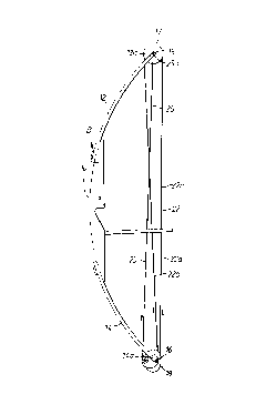
Fig. l is a side elevational view showing one
form of the invention,
Figs. 2 and 3 are opposite side views of he
cam shown generally in Fig. l;
Fig. 4 is a top plan view of the cam wheel
shown in Figs. 2 and 3 with segments of the cables
trained in the grooves thereof;
Fig. 5 is a side elevational view of an
alternate form of cam embodying this invention;
Fig. 6 is a view of another form of cam
embodying this invention;
DETAILED DESCRIPTION OF THE INVENTION
In the accompanying drawings, an archery bow
assembly B is illustrated which includes a central
handle portion l0, having a pair of limbs 12 and 14,

CA 02089799 1998-03-04
-
connected at their inner ends in fixed relation to the
handle portion 10. The limbs 12 and 14 provide the
desired resistance to bending which determines the draw
weight of the bow and the force with which the arrow is
S discharged.
As shown in Figs. 1-4, the outer ends of the
bow elements provide wheel receiving slots which define
wheel mounting forks, respectively designated by the
numbers 12a and 14a, for mounting axle pins 15 and 16.
A pulley 17 is concentrically mounted on the axle pin
15. In this form of the invention, the pulley 17 is
provided with a single groove. As shown in Figs. 2-4,
one form of eccentric cam 18 is mounted on an axle pin
16 and, in the form shown in Figs. 2-4, has three
eccentrically oriented grooves, 18a, 18b, and 18c formed
in the outer periphery thereof to provide three separate
cable groove paths.
A cable 22 has a medial portion trained around
concentric pulley wheel 17 to form a main cable section
or bow-string 22a and a secondary or return section 22b,
both of which extend across the bow to the cam 18. The
end portions of the two sections 22a and 22b are
respectively received in grooves 18b and 18c of the cam
18. The ends 22c and 22d of the sections 22a and 22b
are anchored to the cam 18 as by the cable anchor pins
l9a and l9b fixed to said cam 18, as best shown in Fig.
2. In the form shown, three (3) anchor pins l9a are
provided to permit adjustment of the tension in cable 22
and bowstring 22a.
An anchor cable 25 is anchored at one end 25a
to the axle pin 15 and passes around the cam groove 18a
on the take-up side of the cam 18. The other end 25b of
cable 25 is attached to anchor pin l9c and positively
ties the two bow limbs 12 and 14 together to form a
direct connection between the limbs 12 and 14.

CA 02089799 1998-03-04
-4-
Alternative forms of the invention are
illustrated in Figs. 5-6, but in each case the dual-
feed-out cable sections 22a and 22b extend outwardly
from the let-off cam unit mounted on the limb 14 of the
S bow in the same manner as described for the form shown
in Figs. 1-4. In Fig. 5, a cam 27 is illustrated having
the feed-out sections 22a and 22b extending outwardly
therefrom toward the concentric pulley 17. The cam 27
has a single groove extending all around its complete
periphery with the cable sections 22a and 22b received
in the groove. The ends of the cable sections are
anchored to an anchor pin 27a fixed to one side of the
cam 27. The anchor cable 25 is also securely anchored
to the anchor pin 27a, as shown in Fig. 5. Another
alternative form of the let-off cam is illustrated in
Fig. 6 which embodies a let-off cam 28 having a single
groove thereon wherein cable sections 22 and 22b are
received. A suitable anchor pin 28a is provided on the
back side of the cam 28 as shown by dotted lines in Fig.
6 and both ends of cable sections 22a and 22b are
secured thereto in the same manner as previously
described. The anchor cable 25 is secured to the anchor
pin 29a of a take-up cam 29 fixed to the cam 28 as shown
in Fig. 6. Both cams are eccentrically mounted on an
axle pin 16 connected to the limb 14 of the bow.
X
;

Representative Drawing
A single figure which represents the drawing illustrating the invention.
Administrative Status

2024-08-01:As part of the Next Generation Patents (NGP) transition, the Canadian Patents Database (CPD) now contains a more detailed Event History, which replicates the Event Log of our new back-office solution.

Please note that "Inactive:" events refers to events no longer in use in our new back-office solution.

For a clearer understanding of the status of the application/patent presented on this page, the site Disclaimer , as well as the definitions for Patent , Event History , Maintenance Fee  and Payment History  should be consulted.

Event History

Description Date
Inactive: Adhoc Request Documented 2018-06-06
Revocation of Agent Requirements Determined Compliant 2018-05-18
Appointment of Agent Requirements Determined Compliant 2018-05-18
Inactive: Expired (new Act pat) 2013-02-18
Letter Sent 2003-11-26
Letter Sent 2003-04-02
Inactive: Correspondence - Transfer 2003-02-03
Inactive: Office letter 2002-12-02
Inactive: Multiple transfers 2002-09-26
Inactive: Prior art correction 1999-07-09
Grant by Issuance 1999-02-16
Inactive: Office letter 1999-01-08
Letter Sent 1998-06-12
Notice of Allowance is Issued 1998-06-12
Inactive: Application prosecuted on TS as of Log entry date 1998-06-05
Inactive: Status info is complete as of Log entry date 1998-06-05
Inactive: First IPC assigned 1998-03-20
Inactive: IPC removed 1998-03-20
Inactive: IPC assigned 1998-03-20
Inactive: Approved for allowance (AFA) 1998-03-17
Pre-grant 1996-11-18
All Requirements for Examination Determined Compliant 1994-03-23
Request for Examination Requirements Determined Compliant 1994-03-23
Application Published (Open to Public Inspection) 1993-10-29

Abandonment History

There is no abandonment history.

Maintenance Fee

The last payment was received on 1998-02-13

Note : If the full payment has not been received on or before the date indicated, a further fee may be required which may be one of the following

  • the reinstatement fee;
  • the late payment fee; or
  • additional fee to reverse deemed expiry.

Please refer to the CIPO Patent Fees web page to see all current fee amounts.

Owners on Record

Note: Records showing the ownership history in alphabetical order.

Current Owners on Record
BEAR ARCHERY, INC.
Past Owners on Record
MATHEW MCPHERSON
Past Owners that do not appear in the "Owners on Record" listing will appear in other documentation within the application.
Documents

To view selected files, please enter reCAPTCHA code :


To view images, click a link in the Document Description column. To download the documents, select one or more checkboxes in the first column and then click the "Download Selected in PDF format (Zip Archive)" or the "Download Selected as Single PDF" button.

List of published and non-published patent-specific documents on the CPD .

If you have any difficulty accessing content, you can call the Client Service Centre at 1-866-997-1936 or send them an e-mail at CIPO Client Service Centre.


Document
Description 
Date
(yyyy-mm-dd) 
Number of pages   Size of Image (KB) 
Abstract 1998-03-04 1 18
Description 1998-03-04 4 164
Drawings 1998-03-04 2 46
Cover Page 1994-02-26 1 22
Abstract 1994-02-26 1 17
Claims 1994-02-26 2 55
Drawings 1994-02-26 2 59
Description 1994-02-26 5 152
Cover Page 1999-02-09 1 39
Representative drawing 1999-02-09 1 4
Claims 1998-03-04 5 184
Claims 1999-02-15 5 184
Commissioner's Notice - Application Found Allowable 1998-06-12 1 164
Courtesy - Certificate of registration (related document(s)) 2003-04-02 1 130
Courtesy - Certificate of registration (related document(s)) 2003-11-26 1 125
Correspondence 2002-12-02 1 13
Fees 2002-02-18 1 36
Fees 1998-02-13 1 46
Fees 2001-02-14 1 36
Fees 1999-02-18 1 43
Fees 2000-01-26 1 38
Fees 1997-02-17 1 37
Fees 1996-06-04 1 39
Fees 1996-02-15 1 29
Fees 1995-02-17 1 25
Prosecution correspondence 1993-02-18 16 530
Prosecution correspondence 1994-06-29 7 743
Prosecution correspondence 1994-06-29 1 40
Prosecution correspondence 1996-11-18 2 92
Prosecution correspondence 1996-08-27 1 31
Correspondence related to formalities 1996-06-04 1 39
Courtesy - Office Letter 1994-04-26 1 69
Correspondence related to formalities 1996-06-04 1 37
Prosecution correspondence 1994-03-23 1 32