Note: Descriptions are shown in the official language in which they were submitted.
W092t04782 2 0 9 0 0 1 ~ PCT/US9l/0s83x
RADIO TELEPHONE SYSTEM SUPPORTING BUSY AND
OUT-OF-RANGE FUNCTIONS
Field of the Invention
This invention relates in general to radio telephone
commllnication systems, and more particularly to those systems
that support busy (in use) and/or out-of-range conditions and
is particularly directed toward a Time Division Duplex (TDD)
radio telephone system supporting busy and out-of-range
functions.
Background of the Invention
In contemporary telephone systems, the telephone user
addresses other radio telephone units or land-line telephones
by entering a telephone number that corresponds to the phone
system address of the user to be contacted. Once the
connection is complete, two way voice or data communications
can take place.
With the growing use of portable radio telephone
(cellular or CT-2) systems as a mode of communication, there
are two normally occurring conditions that can prevent the
establishment of a radio frequency link with a base station
(e.g. Telepoint): all channels of the base station may be BUSY
handling other calls, or the portable radio telephone
attempting to access the system may be out-of-range.
It is desirable to be able to indicate to the user which
of the two conditions is responsible, because in the BUSY case
the user merely needs to wait for a channel to become
available, while in the out-of-range case, the user needs to
move closer to the Telepoint. It is easy enough to provide
status indicators on the radio telephone to visually indicate
either the BUSY or the out-of-range conditior., but the CGmmon
Air Interface (CAI) specification, on which the CT-2 system is
based, makes it difficult to determine which of the two
conditions has prevented the establishment of a link.
- - 20qO0 1 4
The difficulty in implementing functional BUSY and out-
of-range indicators arises because the CT-2 system uses a Time
Division Duplex (TDD) transmission scheme on a single RF
channel. TDD optimizes the use of the available radio
frequency spectrum by allowing transmission of voice and data
in both directions between the Telepoint and the portable
radio telephone. Specifically, the radio telephone and the
Telepoint alternately transmit and receive one-millisecond
bursts of information every two milliseconds, one receiving
while the other transmits. The CAI specification, however,
provides no reliable way for an unsynchronized receiver
monitoring an active channel on which a call is in progress to
tell whether it is monitoring a transmission from a radio
telephone or from a Telepoint at any given moment in time.
Under most circumstances, to originate a call, the user
must travel within range of a Telepoint and activate a
transmitter in the user's radio telephone, thus placing the
call. However, this simple scenario does not address the case
where the user cannot determine whether the user is in range
of the Telepoint, or if the Telepoint has any channels
available for co~lnication.
Summary of the Invention
Briefly, according to the invention, there is provided a
radio telephone communication system comprising a base
station with at least one frequency agile transceiver
capable of time division duplex operation on at least one
radio frequency channel. The base station operates to
facilitate communication with at least one radio
telephone on the at least one radio frequency channel.
The radio telephone communication system further
comprises a radio telephone capable of determining an
acquisition status of the at least one frequency agile
transceiver in the base station, the radio telephone
generating an indication representing a base station busy
status when one of: requesting a time division duplex
communication link fails and bidirectional time division
duplex communication is exists on the radio frequency
~0~00 1 4
2a
channel; and re~uesting a time division duplex
communication link fails and unidirectional time division
duplex communication exists on the radio frequency
channel and the unidirectional time division duplex
communication originates from the base station.
-- ~0900 1 4
Brief Description of the Drawings
FIG. 1 is a block diagram of a radio telephone suitable
for use with the present invention.
FIG. 2 is a block diagram of a base station suitable for
use with a Time Division Duplex (TDD) co~nication system as
discussed in the present invention.
FIG. 3 is an front isometric view of the radio telephone
of FIG. 1.
FIG. 4 is an illustration of the information display in
FIG. 3 showing BUSY and out-of range indicators in accordance
with the present invention.
FIG. 5A illustrates TDD tr~nsmissions where the received
signal strength is above the ~;ni~llm threshold for both the
lS radio telephone and the Telepoint.
FIG. 5B illustrates TDD transmissions where the received
signal strength is above the m; ni mllm threshold one of either
the radio telephone or the Telepoint.
FIG. SC illustrates TDD trAnsm;ssions where the received
signal strength is below the m; n; m~lm threshold for both the
radio telephone and the Telepoint.
FIG. SD illustrates TDD transmissions and receiver sample
points where the received signal strength is above the m; n; mllm
threshold for both the radio telephone and the Telepoint.
FIG. SE illustrates TDD transmissions and receiver sample
points where the received signal strength is above the m; n; m
threshold one of either the radio telephone or the Telepoint.
FIG. SF illustrates TDD transmissions and receiver sample
points where the received signal strength is below the m; n; mllm
threshold for both the radio telephone and the Telepoint.
FIG. 6 is a flow diagram showing a method for determining
the acquisition status of at least one frequency agile
transceiver in the base station by a radio telephone in
accordance with the present invention.
~,
`- 209001 4
Description of a Preferred ~mbodiment
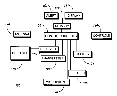
Referring to FIG. 1, a block diagram is shown of a
battery (energy source) 101 powered radio telephone 100.
Operationally, a radio frequency signal is received or
transmitted by the antenna 102. The antenna is coupled to the
receiver 103 and transmitter 104 by a diplexer 105. The
received signal is routed from the receiver 103 to the control
circuitry 106 that recovers any information represented by the
received signal. The recovered information is then used to
activate functions within the radio telephone 100 such as the
alert 107 (a ringer in the case of a radio telephone), and
after answering the call, sustain the connection. When a
connection is established, the user aurally communicates with
the other party via the speaker 108 and a microphone 109.
Recovered audio from the control circuitry 106 is routed to
the speaker 108 which converts electrical energy into
acoustical energy thus enabling the user to hear any
commllnications. The microphone 109 is used to convert
- 20 acoustic energy into electrical energy for use by the control
circuitry 106 in modulating the radio frequency carrier
produced by the transmitter 104. The user may initiate a call
by selecting on a keypad 205 the proper controls 110
representing the number of a party to be contacted.
Before dialing, the desired number is preferably
presented on a display 111 which provides visual feedback for
the user. If desired, the user may either place the call,
edit the number, or abort the dialing operation. When a call
is initiated, the transmitting means 106, 104, 105, 102,
broadcasts a modulated radio frequency carrier having
information representative of the PSTN access codes, both
alternate (limited or controlled access) and standard (local).
The radio telephone base (Telepoint) or an alternate unit
operates to establish a communication link once proper
identification is confirmed.
Referring to FIG. 2, a block diagram is shown of a base
station system (200). The base station's purpose is to
establish and maintain (for the duration of a call) a
W092/04782 PCT/US91/0583X
20900145
communication link between a telephone (201) and a radio
telephone as shown in FIG. 1. The telephone (201)
communicates with the base station (203) via a telephone
network (202). The base station is capable of receiving a
5 plurality of telephone links (or lines) using its telephone
interface (204) that acts to route the incoming and outgoing
traffic to a transmitter/receiver pair as selected by the
system processor (205). The system processor (205) controls
the telephone interface (204) and allocates via an I/O
multiplexer (206) one transmitter/receiver pair per incoming
or outgoing telephone line. The transmitter/receiver pairs
are part of a bank of frequency agile modular transceivers
(207) that can be easily expanded to meet the traffic demands
for a particular system. In implementing a system that meets
the CT-2 (cordless telephone - two) CAI specification, each
transmitter/receiver pair must be capable of time division
duplex operation (TDD) over the same radio frequency channel.
TDD operation for this application is defined by the alternate
transmission and reception, by both the radio telephone and
the selected transmitter/receiver pair at the base station, of
radio frequency information packets (e.g., digital or analog
modulation carrying voice or data information). That is, when
one unit transmits, the other unit listens. This information
transfer method (TDD) yields the equivalent to a full duplex
communication link, on a single radio frequency channel.
Referring to FIG. 3, the front isometric view of the
radio telephone 300 shows the antenna 301, radio telephone
housing 302, loudspeaker 303, display 304, control pad
including a dialing keypad 306 and associated operational
controls 305 such as a clear key, function key, recall key,
and function key, and a microphone 307. Electrical contacts
(not shown) located on the back of the radio telephone 300 are
provided for charging the removable power source in the radio
telephone. For example, charging is accomplished by folding
the lower articulated portion upward against the control pad
305 then inserting the folded unit into a charging apparatus
(not shown). Alternatively, a portable power adapter can be
W092/04782 PCT/US91/0583X
2090014 6
coupled into a power jack located on the radio telephone 300
for charging the power source or supplying external power.
When the user invokes the call mode on the radio
telephone 300, the controller circuitry 106 scans the controls
ll0. Preferably, the user may abort the call mode at any time
by entering an "escape" keystroke or waiting for the entry
mode to "time out." When the user enters initial digits, the
controller processes this first information for acceptance as
valid digits and displays the digits. When a valid access
code or number has been entered, it is presented, thus
providing feedback and allowing the user to accept or reject
the code entered. If the digits entered are incorrect the
user may press the CLR (clear) function key clearing the
present entry and returning to enter new digits. If the
digits displayed are correct, the user may choose to dial the
number by depressing the SND (send) function key which
initiates transmission of the call information. The user may
optionally replace the displayed number with a stored number
by activating the RCL (recall) function key, entering the
stored number's code or memory number, determ;~;ng if the code
is correct and valid, and displaying the newly recalled stored
number. The number to be dialed is then presented on a
display to the user for verification. The user can then
accept or reject the transmission of the num.ber. When the
user is ready to transmit the number (initiate a call), the
SND (send) function is selected and transmission of the
calling information takes place. If the user rejects
transmission or, after dialing has been completed, the call
initiation sequence returns control to normal standby radio
telephone functions.
Referring to FIG. 4, an information display ~400) is
shown that comprises a character display means (401), a BUSY
(402), an OUT-OF-RANGE (403) indicator, and a ROAM (404)
indicator. The character display means (401) is capable of
presenting either numeric or alphanumeric information
representing a phone number or an alias (i.e., a name or
phrase) to a phone number.
~9;~ 1 4
Referring to FIG. 5A, when a radio telephone has
attempted and failed to establish link with a base station,
the radio telephone receiver may begin a scan of all possible
channels in an effort to determine why the failure occurred.
If the radio telephone is able to find a channel on which
adequate signal strength (greater than a predetermined
amplitude, 501) is present in both directions (i.e.,
continuous bidirectional transmissions with no 1 mS gaps),
then it is reasonable to assume that the radio telephone is
monitoring transmissions from both another radio telephone
(502) and a base station (503), although no determination can
be made as to which transmission originates from the base and
which from the other radio telephone. In this circumstance,
the reason for the failure to establish link cannot be that
the radio telephone is out-of-range; therefore, the reason
must be that all channels of the base station are busy.
Accordingly, in this case, the user should be notified of a
channel busy status.
Referring to FIG. 5B, when a radio telephone has
attempted and failed to establish link with a base station,
and a scan of all possible CT-2 channels has found no channel
upon which adequate signal strength (504) is present in both
directions, but has found one or more channels on which there
is adequate signal strength in one direction (505) (i.e., 1 mS
signals with 1 mS gaps), an uncertainty exists. If none of
the signals originate from a base station, the reason for the
failure to establish link must be because the radio telephone
is out-of-range of any base station. If at least one of the
signals originates from a base station, then the associated
base station is in range and therefore must be busy
(otherwise, the link would have been established).
-
~'0 92/04782 PC~r/US91/0583X
,~, 2090014
Referring to FIG. 5C, when a radio telephone has
attempted and failed to establish link with a base station,
and a scan of all possible CT-2 channels has found no channel
on which adequate signal strength (506) is present in either
direction, it is apparent that the reason for the failure to
establish link is that the radio telephone is out-of-range.
Referring to FIG. 5D, 5E, and 5F, when a radio telephone
has attempted and failed to establish link with a base
station, the radio telephone receiver may begin a scan of all
possible channels in an effort to determine why the failure
occurred. The first step in determi ni ng the cause of a
failure to establish a link is to measure the signal strength
on each of the 40 possible CT-2 channels. Because the radio
telephone, having failed to establish a link, is
unsynchronized with the base station, a mi nim-lm of four signal
strength measurements (507, 508, 509, 510) are preferably made
at 500 microsecond intervals in order to determine whether the
radio telephone is receiving both, one, or none of the
possible TDD transmissions on each channel. For each of the
preferably 40 channels, the largest of the four signal
strength measurements should be retained along with one other
measurement offset from it by one millisecond in either
direction, while the r~m~i ni ng two measurements should be
discarded. Having determined for each of the 40 channels
whether both, one, or none of the possible TDD transmission
directions are above a predetermined signal strength (511),
the following conclusions about the cause of the failure to
establish link may be possible:
a) a channel with bidirectional communication (FIG. 5D)
means that the base station is busy;
b) channels with unidirectional communication (FIG. 5E)
are indeterminate; and
c) no transmissions on any channel (FIG. 5F) means that
the base station is out-of-range.
To determine the status in case b), the origin of any of
the single-direction (unidirectional) signals needs to be
found. If a single-direction signal is coming from a base
station, the channel status is busy. If a single-direction
W092/04782 PCT/US91/0583X
2 0~ 0~1~
g
signal is coming from a radio telephone, the channel status is
out-of-range.
The CT-2 CAI specification does not provide any implicit
differentiation between the signals transmitted by the base
station and those of the radio telephone. However, the
specification does allow certain types of messages to be
transmitted exclusively by either the base or the radio
telephone. For example, only the base is allowed to transmit
messages intended to control the radio telephone's display,
thus yielding a base-identifying message.
In its preferred embodiment, this invention makes use of
the aforementioned exclusivity in order to identify the source
of a single-direction signal, and thus to overcome the
indeterminate situation with regard to the cause of failure to
establish link. The invention preferably uses the periodic
transmission of a radio telephone display message as base-
identifying message for signals transmitted by the base
station (e.g., the NULL display character would be a good
cholce, as it will be ignored by the radio telephone according
to the present CAI specification).
Whenever a scan of all channels produces only channels
with single-direction (unidirectional) transmissions, the
radio telephone must synchronize itself with the data channel
having one of the single-direction signals and begin searching
for the presence of the periodically transmitted radio
telephone display message. If such a message is found on the
channel, then the signal must be from a base station, and the
search may be ended with the conclusion that the base station
is busy. If the message is not found on the channel, then the
signal must be from another radio telephone, and the search
must proceed to the next channel, and continue until all
channels with single-direction signals have been searched
without finding the base-identifying message, at which time an
indication is provided representing a channel out-of-range
status meaning that all base stations are out-of-range.
Accordingly, in this case, the user should be notified of a
channel out-of-range status.
_ 20900 1 4
Referring to FIG. 6, the radio telephone (or
handset) that has failed to establish a link (601)
operates to measure and save (samples) the power spectrum
associated with the channel in both TDD directions at a
predetermined time interval (602). Step 603 tests the
stored signal strengths to determine if the signal
strength indication is above a predetermined magnitude.
The predetermined magnitude is nominally set at a level
that corresponds to a lack of an interfering signal on
the channel in question. By choosing the level
judiciously, the system designer can eliminate any
possibility of a signal on an adjacent channel from
interfering with the proper detection of the channel
status. If the measured signal strengths are above the
predetermined magnitude and bidirectional communication
exists (both directions are present), control is passed
to step 604 and an indication representing a base station
busy status is provided. In the case where both signal
strength are not above minimum, control is passed to step
605 where the controller tests for all channels having
been measured. If all channels have not been measured,
step 606 moves to the next channel and returns to step
602 to measure and save the channel's levels. Once all
channels have been measured, step 605 passes control to
step 607 that tests for the presence or absence of
unidirectional channels. If any unidirectional channels
were found, step 608 synchronizes with the received
signal to determine if communication exists on the
channel in question. Step 609 then tests the channel for
a unidirectional communication including at least a
signal validly transmitted only by the base station. If
step 609 is true an indication representing a base
station busy status is provided (604). If step 609
fails, that is the unidirectional communication lacks at
least a signal validly transmitted only by the base
station, control is passed to step 610 that tests for all
unidirectional channels having been scanned. If they
- ` ~0~0~ 1 4
11
have not, step 610 advances to step 611, subsequently
advancing the channel pointer and returning control to
step 608. If all unidirectional channels having been
scanned, step 610 passes control to step 612 which
provides an indication representing a base station out-
of-range status.