Language selection

Search

Patent 2090041 Summary

Third-party information liability

Some of the information on this Web page has been provided by external sources. The Government of Canada is not responsible for the accuracy, reliability or currency of the information supplied by external sources. Users wishing to rely upon this information should consult directly with the source of the information. Content provided by external sources is not subject to official languages, privacy and accessibility requirements.

Claims and Abstract availability

Any discrepancies in the text and image of the Claims and Abstract are due to differing posting times. Text of the Claims and Abstract are posted:

  • At the time the application is open to public inspection;
  • At the time of issue of the patent (grant).
(12) Patent: (11) CA 2090041
(54) English Title: CHAIN CONVEYOR
(54) French Title: TRANSPORTEUR A RACLETTES
Status: Term Expired - Post Grant Beyond Limit
Bibliographic Data
(51) International Patent Classification (IPC):
  • B65G 15/20 (2006.01)
  • B27B 31/06 (2006.01)
  • B65G 17/26 (2006.01)
  • B65G 21/12 (2006.01)
(72) Inventors :
  • RAUTIO, KAUKO (Finland)
(73) Owners :
  • KAUKO RAUTIO
(71) Applicants :
  • KAUKO RAUTIO (Finland)
(74) Agent: OYEN WIGGS GREEN & MUTALA LLP
(74) Associate agent:
(45) Issued: 1997-10-14
(22) Filed Date: 1992-12-18
(41) Open to Public Inspection: 1993-07-14
Examination requested: 1994-06-23
Availability of licence: N/A
Dedicated to the Public: N/A
(25) Language of filing: English

Patent Cooperation Treaty (PCT): No

(30) Application Priority Data:
Application No. Country/Territory Date
920140 (Finland) 1992-01-13

Abstracts

English Abstract


The invention relates to a chain conveyor, for example for
conveying sawn wood after a sawing machine, the chain conveyor
being made up of two adjacent conveyor chains on top of which
the conveyor flights supporting sawn wood are located. The
conveyor flight is articulated in such a manner that the width
of the entire chain conveyor can be regulated by adjusting the
distance between the conveyor chains.


French Abstract

L'invention concerne un convoyeur à chaîne, par exemple pour le transport de bois scié à sa sortie d'une machine à scier, le convoyeur pouvant être constitué de deux chaînes de transport contiguës, au-dessus desquelles se trouvent les étages de convoyeur supportant le bois scié. Le convoyeur est articulé de manière que la largeur du convoyeur à chaîne complet peut être réglée en agissant sur la distance entre les chaînes du convoyeur.

Claims

Note: Claims are shown in the official language in which they were submitted.

THE EMBODIMENTS OF THE INVENTION IN WHICH AN EXCLUSIVE
PROPERTY OR PRIVILEGE IS CLAIMED ARE DEFINED AS FOLLOWS:
1. A chain conveyor for conveying sawn wood comprising
at least two adjacent conveyor chains spaced apart by a
predetermined variable distance and conveyor flights located
on top of the chains and including means for supporting sawn
wood, wherein the support means of the conveyor flights
comprises articulated support surfaces positioned on top of
and above the chains and pivotally connected such that the
width of the entire chain conveyor can be adjusted to the
desired width by adjusting the distance between the conveyor
chains.
2. A chain conveyor according to claim 1, wherein the
conveyor flight support surfaces are articulated at the center
of the conveyor in such a manner that they form a V-angle
which is obtuse when the chain conveyor is in a wide position
and acute when the chain conveyor is in a narrow position,
wherein the chain conveyor width can thus be adjusted
steplessly.
3. A chain conveyor according to one of claims 1 or 2,
wherein the conveyor chains run in chain guides and the width
of the conveyor can be adjusted by articulating the conveyor
flight support surfaces.
4. A chain conveyor according to one of claims 1 or 2

which further comprises a guide rail positioned between the
conveyor chains and connected to the support surfaces of the
conveyor flights.
5. A chain conveyor according to claim 4 wherein the
conveyor flights include first and second support surfaces
each having a first and second end, with the first ends
pivotably connected to the conveyor chains and the second ends
pivotably connected to the guide rail and each other to form
an articulated joint such that linear movement of the guide
rail causes pivotal movement of the support surfaces and a
change in the width of the conveyor.
6. A chain conveyor according to claim 5 wherein a
plurality of conveyor flights are provided with each flight
connected in the same manner so that the angles formed by the
support surfaces is the same and is oriented in the same
direction for each flight.
7. A chain conveyor according to one of claims 1 or 2
wherein the support surfaces include a chain a belt or a
spring steel strip.

Description

Note: Descriptions are shown in the official language in which they were submitted.


2~0~
Chain conveyor
The present invention relates to a chain conveyor, for example,
for conveying sawn wood after the sawing machine, the chain
conveyor being made up of at least two adjacent conveyor chains
on top of which the conveyor flights supporting the sawn wood
are located.
In prior known devices, the conveyor flights supporting sawn
wood are various flat bar steels, having the length of two
chains and being fixedly installed transversely on top of the
chain so that they extend beyond the chain by as much as the
width of the chain. When the chains are positioned adjacently,
the flat bar steel is equally much also on top of the second
chain. This is a simple structure, but the maximum width of the
conveyor is only twice the minimllm width. Using a conveyor
wider than a bundle of sawn wood, from which conveyor the
boards are transferred by means of blades or guides to board
conveyors on the sides of the conveyor, sufficient board-
ejection force cannot be achieved. A subse~uent board must push
the preceding one, and thus they will fall irregularly onto the
side conveyors. The boards will wedge against each other, espe-
cially if they are waney. The object of the invention is to
eliminate the disadvantages described above and to provide a
new-type chain conveyor with a regulatable width. The chain
conveyor according to the invention is characterized in that
the conveyor flight is articulated in such a manner that the
width of the entire chain conveyor can always be adjusted to
sufficient width by adjusting the distance between the conveyor
chains. The system according to the invention separates surface
boards from the center yield by dropping them to outside the
conveyor while the center yield will continue forward. The
boards are supported by pressure against the center yield by
the driving wheels until they are entirely outside the sawing
machine.

209~0~
One embodiment of the invention is characterized in that the
conveyor flight is articulated at its center in such a manner
that it forms a V-angle which is obtuse when the chain conveyor
is in a wide position and acute when the chain conveyor is in a
narrow position, and that the width o~ the chain conv~yor can
thus be regulated steplessly.
Another embodiment o~ the invention is characterized in that
the conveyor chains run in chain guides by which the conveyor
width can be regulated. Between the conveyor chains there is
further a guide rail or chain supporting the conveyor flights.
A chain conveyor such as this is simple; it is economical to
manufacture and reliable in operation.
The invention is described below with the help of an example,
with reference to the accompanying drawing, in which
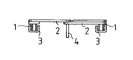
Figures 1, 2 and 3 depict end, top and side views of a section
of the conveyor chain in a wide position,
Figures 4, 5 and 6 depict the same chain conveyor, but in a
narrow position,
Figures 7 and 8 depict top views of alternative conveyor
flights, in which they are, according to Figure 7, a chain 5
and, according to Figure 8, a belt 6 or a spring steel strip.
The chain conveyor is made up of two adjacent conveyor chains
1, on top of which the conveyor flights 2 conveying sawn wood
are located. The conveyor flight 2 is articulated in such a
manner that the width of the entire chain conveyor can be regu-
lated by adjusting the distance between the conveyor chains.
The conveyor chain 2 is articulated at its center in such a
manner that it forms a V-angle which is obtuse when the chain
conveyor is in a wide position, Figures 1-3. The V-angle is
acute when the chain conveyor is in a narrow position, Figures

~9~
4-6. The width of the chain conveyor can thus be adjusted step-
lessly. The conveyor chains 1 run in chain guides 3, by which
the conveyor width can be adjusted. Between the conveyor chains
1 there is a guide rail 4 which supports the conveyor flights
2. Since the motor, power transmission, and width-regulating
devices belonging to the chain conveyor are systems and appli-
cations known per se, these devices are not described in the
present patent application.

Representative Drawing
A single figure which represents the drawing illustrating the invention.
Administrative Status

2024-08-01:As part of the Next Generation Patents (NGP) transition, the Canadian Patents Database (CPD) now contains a more detailed Event History, which replicates the Event Log of our new back-office solution.

Please note that "Inactive:" events refers to events no longer in use in our new back-office solution.

For a clearer understanding of the status of the application/patent presented on this page, the site Disclaimer , as well as the definitions for Patent , Event History , Maintenance Fee  and Payment History  should be consulted.

Event History

Description Date
Inactive: Expired (new Act pat) 2012-12-18
Inactive: Office letter 2007-02-16
Inactive: Corrective payment - s.78.6 Act 2007-01-17
Inactive: IPC from MCD 2006-03-11
Inactive: Late MF processed 2003-12-08
Inactive: Entity size changed 2002-01-03
Inactive: Applicant deleted 1997-12-03
Grant by Issuance 1997-10-14
Inactive: Inventor deleted 1997-09-30
Inactive: Status info is complete as of Log entry date 1997-08-11
Inactive: Application prosecuted on TS as of Log entry date 1997-08-11
Pre-grant 1997-05-16
Notice of Allowance is Issued 1996-12-03
All Requirements for Examination Determined Compliant 1994-06-23
Request for Examination Requirements Determined Compliant 1994-06-23
Application Published (Open to Public Inspection) 1993-07-14

Abandonment History

There is no abandonment history.

Maintenance Fee

The last payment was received on 

Note : If the full payment has not been received on or before the date indicated, a further fee may be required which may be one of the following

  • the reinstatement fee;
  • the late payment fee; or
  • additional fee to reverse deemed expiry.

Please refer to the CIPO Patent Fees web page to see all current fee amounts.

Fee History

Fee Type Anniversary Year Due Date Paid Date
Final fee - standard 1997-05-16
MF (patent, 5th anniv.) - small 1997-12-18 1997-12-08
MF (patent, 6th anniv.) - standard 1998-12-18 1998-11-30
MF (patent, 7th anniv.) - standard 1999-12-20 1999-12-06
MF (patent, 8th anniv.) - standard 2000-12-18 2000-11-14
MF (patent, 9th anniv.) - standard 2001-12-18 2001-12-12
MF (patent, 10th anniv.) - standard 2002-12-18 2002-11-22
MF (patent, 11th anniv.) - standard 2003-12-18 2003-12-08
MF (patent, 12th anniv.) - standard 2004-12-20 2004-12-03
MF (patent, 13th anniv.) - standard 2005-12-19 2005-11-21
MF (patent, 14th anniv.) - standard 2006-12-18 2006-11-27
2007-01-17
MF (patent, 15th anniv.) - standard 2007-12-18 2007-11-29
MF (patent, 16th anniv.) - standard 2008-12-18 2008-11-24
MF (patent, 17th anniv.) - standard 2009-12-18 2009-12-07
MF (patent, 18th anniv.) - standard 2010-12-20 2010-12-07
MF (patent, 19th anniv.) - standard 2011-12-19 2011-11-23
MF (application, 2nd anniv.) - small 02 1994-12-19
Owners on Record

Note: Records showing the ownership history in alphabetical order.

Current Owners on Record
KAUKO RAUTIO
Past Owners on Record
None
Past Owners that do not appear in the "Owners on Record" listing will appear in other documentation within the application.
Documents

To view selected files, please enter reCAPTCHA code :


To view images, click a link in the Document Description column. To download the documents, select one or more checkboxes in the first column and then click the "Download Selected in PDF format (Zip Archive)" or the "Download Selected as Single PDF" button.

List of published and non-published patent-specific documents on the CPD .

If you have any difficulty accessing content, you can call the Client Service Centre at 1-866-997-1936 or send them an e-mail at CIPO Client Service Centre.


Document
Description 
Date
(yyyy-mm-dd) 
Number of pages   Size of Image (KB) 
Claims 1996-12-03 2 60
Cover Page 1997-10-03 1 31
Abstract 1993-11-27 1 11
Claims 1993-11-27 1 26
Cover Page 1993-11-27 1 12
Drawings 1993-11-27 2 27
Description 1993-11-27 3 92
Representative drawing 1997-10-03 1 3
Fees 1997-12-08 1 43
Correspondence 2007-02-16 1 13
Fees 1994-12-09 1 43
Fees 1996-11-27 1 43
Fees 1995-12-08 1 41
Courtesy - Office Letter 1994-08-28 1 74
PCT Correspondence 1997-05-16 1 34
Prosecution correspondence 1994-11-10 1 37
Examiner Requisition 1995-01-13 1 66
Prosecution correspondence 1995-07-12 1 58
Prosecution correspondence 1994-06-23 1 47