Language selection

Search

Patent 2090319 Summary

Third-party information liability

Some of the information on this Web page has been provided by external sources. The Government of Canada is not responsible for the accuracy, reliability or currency of the information supplied by external sources. Users wishing to rely upon this information should consult directly with the source of the information. Content provided by external sources is not subject to official languages, privacy and accessibility requirements.

Claims and Abstract availability

Any discrepancies in the text and image of the Claims and Abstract are due to differing posting times. Text of the Claims and Abstract are posted:

  • At the time the application is open to public inspection;
  • At the time of issue of the patent (grant).
(12) Patent: (11) CA 2090319
(54) English Title: CABIN, ESPECIALLY FOR A CROSS-COUNTRY VEHICLE
(54) French Title: CABINE, EN PARTICULIER POUR VEHICULE TOUT-TERRAIN
Status: Expired and beyond the Period of Reversal
Bibliographic Data
(51) International Patent Classification (IPC):
  • B62D 33/10 (2006.01)
  • B62D 33/06 (2006.01)
  • E02F 9/16 (2006.01)
(72) Inventors :
  • NYSTROM, STEN (Sweden)
(73) Owners :
  • TIGERCAT INDUSTRIES INC.
  • MALA SKOGSTJANST AB
(71) Applicants :
  • TIGERCAT INDUSTRIES INC. (Canada)
  • MALA SKOGSTJANST AB (Sweden)
(74) Agent:
(74) Associate agent:
(45) Issued: 2001-04-24
(86) PCT Filing Date: 1991-08-22
(87) Open to Public Inspection: 1992-03-19
Examination requested: 1997-10-06
Availability of licence: N/A
Dedicated to the Public: N/A
(25) Language of filing: English

Patent Cooperation Treaty (PCT): Yes
(86) PCT Filing Number: PCT/SE1991/000556
(87) International Publication Number: WO 1992004224
(85) National Entry: 1993-12-24

(30) Application Priority Data:
Application No. Country/Territory Date
9002771-5 (Sweden) 1990-08-30

Abstracts

English Abstract


A cabin intended primarily for cross-country
vehicles and supported at the top thereof by a
carrier frame (2) mounted on the vehicle. The cabin
(1) is freely suspended from the carrier frame (2)
by means of a carrier device (3) which is so located
in relation to a vertical line which passes through
the centre of gravity of the cabin (1) that the cabin
will always be located essentially in the horizontal
plane. The cabin is also connected to the carrier
frame (2) by means of shock absorbers (5) which
are spaced from the carrier device.


French Abstract

Cabine destinée notamment aux véhicules tout-terrain et portée au niveau de son extrémité supérieure par un cadre porteur (2) monté sur le véhicule. La cabine (1) est suspendue librement à partir du cadre porteur (2) par l'intermédiaire d'un dispositif porteur (3) dont le positionnement par rapport à une ligne verticale traversant le centre de gravité de la cabine (1) est tel que la cabine se trouve en permanence dans un plan essentiellement horizontal. Ladite cabine est également reliée au cadre porteur (2) par l'intermédiaire d'amortisseurs (5) écartés dudit dispositif porteur (3).

Claims

Note: Claims are shown in the official language in which they were submitted.

-5-
The embodiments of the invention in which an exclusive property or privilege
is claimed are defined as follows:
1. A cross-country vehicle for maneuvering over uneven terrain,
comprising:
a chassis supported for movement upon uneven terrain and including a
cabin carrier frame for hangingly suspending an operator's cabin for the
vehicle;
an operator's cabin having a center for gravity;
a universal joint suspending said cabin from above, from said carrier
frame for omnidirectionally pendular swinging motion relative to a pivot point
provided by said universal joint, so that said center of gravity of said
operator's cabin
tends to lie on an imaginary straight line connecting said pivot point with
the center of
the earth; and
a plurality of two ended shock absorbers equiangularly spaced from
one another about said line and each having one end effectively connected with
said
carrier frame and an opposite end effectively connected with said cabin, both
with
radial spacing from said line, for damping tendency of said cabin to
omnidirectionally
pendularly oscillate as said vehicle traverses uneven terrain.
2. The cross-country vehicle of claim 1, wherein:
there are four said shock absorbers; said cabin has a top wall, and
respective of said opposite ends of said shock absorbers are connected with
said cabin
at respective points on said top wall.
3. The cross-country vehicle of claim 2, wherein:
said cabin is square in plan, so as to have four corners, and said
respective points are located centrally between respective adjoining ones of
said
corners.

-6-
4. The cross-country vehicle of claim 1, wherein:
said shock absorbers converge towards one another from said opposite
ends towards said one ends thereof.
5. The cross-country vehicle of claim 1, wherein:
said universal joint is provided on a motorized yoke mounted to said
carrier frame;
said one ends of said shock absorbers are effectively connected with
said carrier frame by being pivotally connected to said yoke; and
further including a motor, effectively mounted between the carrier
frame and the universal joint for rotating said cabin around said line under
control of
an operator disposed in said cabin.

Description

Note: Descriptions are shown in the official language in which they were submitted.


WO 92/04224 PCT/SE91/00555 -
2n90~1~
Cabin. Especially for a Cross-Country Vehicle
The present invention rElates to a cabin intended
primarily for a cross-country vehicle in accordance
with the preamble of Claim 1.
-The operator cabins of cross-country vehicles, such as
forest tractors and forest harvesters, are affixed to
the vehicle chassis and therewith accompany all of the
movements performed by the vehicle in the terrain.
These movements may have large amplitudes and powerful
accelerations and retardations, in lateral, forward and
rearward directions: This often makes the work of the
driver very difficult and highly strenuous, since in
addition to manoeuvring the vehicle, he must also
remain firmly seated in the drivers seat.
In order to solve this problem and therewith provide
improved working conditions for the driver of the
vehicle concerned, endeavours have been made to support
the driving seats on gyro suspensions, to manoeuvre the
cabins hydraulically from beneath, and to incorporate
different types of hydraulically operable axle pen-
dulating systems for adjusting the vehicle wheels in
relation to the chassis. Examples of these proposed
solutions are found described in SE-8200443-3 and SE-
8304292-9. These known systems are complicated and
expensive.
The aforesaid problem is eliminated by means of the
present invention which has the characteristic features
set forth in the following Claims.
The present invention will now be described in mare
detail with reference to an exemplifying embodiment
thereof and with reference to the accompanying

WO 92/04224 PCTlSE91/00556
~~~~~~.~~
2
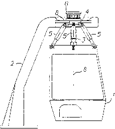
drawings, in which Figure 1 is.a schematic illustration
of a cabin, for example the driver's cabin and operat-
ing cabin of a forest harvester; Figure 2 illustrates
the cabin mounted on the harvester, which in the il-
lustrated example is inclined in the longitudinal
plane; and Figure 3 illustrates the cabin when the
-vehicle inclines about its longitudinal axis, this
angle being 30° in the illustrated case.
In the Figures, the reference numeral 1 identifies a
cabin, for example the driving and operating cabin of a
forest harvester, and 2 identifies a support device in
the form of a cabin carrying frame which, as shown in
Figure 2, is fixedly attached to the vehicle.
The cabin 1 is suspended from the carrier frame 2 by
means of a carrier device 3 and when the cabin is
manned and is located in the horizontal plane, the
cabin will hang in a vertical line 8 which passes
through the centre of gravity of the cabin 1. The
carrier device 3 includes a universal joint (for ex-
ample a cardan joint), whereby the cabin is suspended
so as to pendulate freely in relation to the vehicle
and its chassis. The carrying device 3 is attached to
the centre of a cruciform yoke 4 which, in turn, is at-
tached to the carxier frame 2 by means of a carrier
plate 9, via a vibration damping connection. The car-
rier device may be attached to the yoke 4 and to the
cabin 1 by means of rubber springs, so as to prevent
the transmission of vibrations and sound from the
vehicle and its machines to the cabin. Four shock
absorbers 5 are mounted in the upper edges of the
cabin, centrally between its corners, by means of ball
bearings mounted on the cabin 1. The other ends of
respective shock absorbers 5 are also fixedly
journalled by means of a ball bearing on respective

WO 92/04224 PCTlSE91100556
2fl9fl3~~
3
arms of the yoke 4. The distances between the points at
which the shock absorbers 5 are attached to the cabin 1
are greater than the distances between the points at
which the shock absorbers are attached to the yoke 4,
as illustrated in the Figures, which means that the
shock absorbers will be inclined from the cabin roof,
-obliquely inwards and upwards.. With a given construc-
tional height of the support frame 2, this enables the
use of shock absorbers 5 having greater lengths of
working stroke than would otherwise be possible if the
shock absorbers were arranged vertically. This inclina-
tion of the shock absorbers 5 also means that the yoke
construction measurement is restricted, which enables
the rotational range of the yoke in the case of a
rotatable cabin, as described herebelow, to be kept ,
relatively small.
The shook absorbers are preferably pneumatic piston-
cylinder devices.
Because the cabin hangs in a vertical line which passes
through its centre of gravity, there is no need to
provide a complicated hydraulic piston-cylinder control
system in order to keep the cabin level which, accord-
ing t~ the present invention, adopts a horizontal
position automatically, irrespective of the angle of
the vehicle in the terrain. The shock absorbers 5 thus
enable the cabin to pendulate without beginning to
oscillate. Vibrations and slewing movements of the
vehicle are effectively dampened by the shock
absorbers.
The shock absorbers 5 may be arranged in a manner which
will enable their damping characteristics to be ad-
justed from within the cabin, either individually
and/or together. This enables the rate of damping to be

WO 92/04224 ~9 ~ v ~ ~' Y PCT/SE91/00556
4
controlled with respect to pendulation in the trans-
verse and longitudinal directions and will also enable
the rate of pendulation to be finely adjusted in
accordance with varying ambient temperatures (winter -
summer ) .
-In the case of the embodimenfi illustrated in Figure 1,
the cruciform yoke 4 is connected either to an electric
or a hydraulic motor 6, by means of which th.e cabin ~.
can be rotated in relation to the carrier frame 2 and
therewith in relation to the vehicle chassis. When
working, for example, with a crane, it is therefore not
necessary for the driver to twist his head, since the
driver is able either rotate the cabin 1 to the best
position for carrying out the work concerned, or the
motor 6 can be coupled to the crane arm or jib 7
(Figure 2), so that the cabin will rotate synchronously
with said arm or jib.
The aforesaid free suspension of the cabin minimizes
the risk of damage to the cabin in the event of the
vehicle toppling, or in the event of a tree falling
onto the cabin or being brought into contact therewith
due to error. The carrier frame 2 functions as a pro-
tective frame and may be given a form appropriate to
this end.
Thus, the present invention provides for automatic
levelling of the cabin without the need for a compli-
Gated control system, thereby greatly facilitating the
work required of the driver, who is able to perform his
work in greater safety and comfort than in the case of
a driver who must constantly counteract impacts, jolts
and rocking motion in conventional cabins.

Representative Drawing
A single figure which represents the drawing illustrating the invention.
Administrative Status

2024-08-01:As part of the Next Generation Patents (NGP) transition, the Canadian Patents Database (CPD) now contains a more detailed Event History, which replicates the Event Log of our new back-office solution.

Please note that "Inactive:" events refers to events no longer in use in our new back-office solution.

For a clearer understanding of the status of the application/patent presented on this page, the site Disclaimer , as well as the definitions for Patent , Event History , Maintenance Fee  and Payment History  should be consulted.

Event History

Description Date
Letter Sent 2023-09-13
Letter Sent 2019-09-10
Time Limit for Reversal Expired 2010-08-23
Inactive: Adhoc Request Documented 2010-06-02
Letter Sent 2009-08-24
Inactive: IPC from MCD 2006-03-11
Letter Sent 2004-12-06
Letter Sent 2004-01-23
Inactive: Office letter 2002-10-23
Revocation of Agent Requirements Determined Compliant 2002-10-23
Revocation of Agent Request 2002-10-02
Inactive: Late MF processed 2002-10-02
Letter Sent 2002-08-22
Inactive: Late MF processed 2001-10-15
Letter Sent 2001-08-22
Grant by Issuance 2001-04-24
Inactive: Cover page published 2001-04-23
Inactive: Final fee received 2001-01-24
Pre-grant 2001-01-24
Letter Sent 2000-11-27
Notice of Allowance is Issued 2000-11-27
Inactive: Approved for allowance (AFA) 2000-10-26
Letter Sent 2000-09-15
Amendment Received - Voluntary Amendment 2000-09-13
Reinstatement Requirements Deemed Compliant for All Abandonment Reasons 2000-09-06
Deemed Abandoned - Failure to Respond to Maintenance Fee Notice 2000-08-22
Letter Sent 2000-08-03
Inactive: Single transfer 2000-07-07
Inactive: S.30(2) Rules - Examiner requisition 2000-03-17
Inactive: Status info is complete as of Log entry date 1997-11-12
Inactive: RFE acknowledged - Prior art enquiry 1997-11-12
Inactive: Application prosecuted on TS as of Log entry date 1997-11-12
All Requirements for Examination Determined Compliant 1997-10-06
Request for Examination Requirements Determined Compliant 1997-10-06
Application Published (Open to Public Inspection) 1992-03-19

Abandonment History

Abandonment Date Reason Reinstatement Date
2000-08-22

Maintenance Fee

The last payment was received on 2000-09-06

Note : If the full payment has not been received on or before the date indicated, a further fee may be required which may be one of the following

  • the reinstatement fee;
  • the late payment fee; or
  • additional fee to reverse deemed expiry.

Please refer to the CIPO Patent Fees web page to see all current fee amounts.

Owners on Record

Note: Records showing the ownership history in alphabetical order.

Current Owners on Record
TIGERCAT INDUSTRIES INC.
MALA SKOGSTJANST AB
Past Owners on Record
STEN NYSTROM
Past Owners that do not appear in the "Owners on Record" listing will appear in other documentation within the application.
Documents

To view selected files, please enter reCAPTCHA code :


To view images, click a link in the Document Description column. To download the documents, select one or more checkboxes in the first column and then click the "Download Selected in PDF format (Zip Archive)" or the "Download Selected as Single PDF" button.

List of published and non-published patent-specific documents on the CPD .

If you have any difficulty accessing content, you can call the Client Service Centre at 1-866-997-1936 or send them an e-mail at CIPO Client Service Centre.


Document
Description 
Date
(yyyy-mm-dd) 
Number of pages   Size of Image (KB) 
Abstract 1995-08-17 1 52
Description 1994-03-26 4 151
Claims 1994-03-26 2 44
Drawings 1994-03-26 3 36
Cover Page 2001-04-10 1 39
Claims 2000-09-13 2 56
Cover Page 1994-03-26 1 13
Representative drawing 2001-04-10 1 6
Acknowledgement of Request for Examination 1997-11-12 1 173
Courtesy - Certificate of registration (related document(s)) 2000-08-03 1 115
Courtesy - Abandonment Letter (Maintenance Fee) 2000-09-15 1 184
Notice of Reinstatement 2000-09-15 1 170
Commissioner's Notice - Application Found Allowable 2000-11-27 1 165
Maintenance Fee Notice 2001-09-19 1 179
Late Payment Acknowledgement 2001-10-26 1 171
Maintenance Fee Notice 2002-09-19 1 177
Late Payment Acknowledgement 2002-10-09 1 168
Notice: Maintenance Fee Reminder 2003-05-26 1 115
Courtesy - Certificate of registration (related document(s)) 2004-01-23 1 107
Notice: Maintenance Fee Reminder 2004-05-26 1 118
Courtesy - Certificate of registration (related document(s)) 2004-12-06 1 106
Notice: Maintenance Fee Reminder 2005-05-25 1 118
Notice: Maintenance Fee Reminder 2006-05-24 1 118
Notice: Maintenance Fee Reminder 2007-05-23 1 121
Notice: Maintenance Fee Reminder 2008-05-26 1 122
Notice: Maintenance Fee Reminder 2009-05-25 1 119
Maintenance Fee Notice 2009-10-05 1 170
Second Notice: Maintenance Fee Reminder 2010-02-23 1 120
Notice: Maintenance Fee Reminder 2010-05-26 1 132
Courtesy - Certificate of registration (related document(s)) 2019-09-10 1 105
Courtesy - Certificate of registration (related document(s)) 2023-09-13 1 353
Fees 2003-06-09 1 64
Fees 2001-10-15 1 31
Fees 1999-07-22 1 28
Fees 2002-10-02 2 134
Correspondence 2002-10-02 2 134
Correspondence 2002-10-22 1 22
Correspondence 2002-10-23 1 13
Correspondence 2002-10-23 1 15
Correspondence 2001-01-24 1 26
PCT 1993-02-24 8 242
Fees 2002-10-02 1 27
Fees 1993-11-12 1 19
Fees 2000-09-06 1 35
Fees 2004-07-14 1 61
Fees 2005-07-04 1 28
Fees 2006-06-15 4 151
Fees 2007-07-24 3 111
Fees 2008-07-31 4 305
Fees 1996-08-15 1 35
Fees 1995-08-11 1 26
Fees 1994-08-11 1 44
Fees 1993-10-05 2 60
Courtesy - Office Letter 1993-10-22 1 23
Courtesy - Office Letter 1993-11-12 1 20