Language selection

Search

Patent 2090424 Summary

Third-party information liability

Some of the information on this Web page has been provided by external sources. The Government of Canada is not responsible for the accuracy, reliability or currency of the information supplied by external sources. Users wishing to rely upon this information should consult directly with the source of the information. Content provided by external sources is not subject to official languages, privacy and accessibility requirements.

Claims and Abstract availability

Any discrepancies in the text and image of the Claims and Abstract are due to differing posting times. Text of the Claims and Abstract are posted:

  • At the time the application is open to public inspection;
  • At the time of issue of the patent (grant).
(12) Patent: (11) CA 2090424
(54) English Title: ROLLER PRESS
(54) French Title: PRESSE A ROULEAUX
Status: Term Expired - Post Grant Beyond Limit
Bibliographic Data
(51) International Patent Classification (IPC):
  • B02C 04/42 (2006.01)
  • B02C 04/32 (2006.01)
(72) Inventors :
  • ANDERSEN, KNUD TONI (Denmark)
(73) Owners :
  • F.L. SMIDTH & CO. A/S
  • F.L. SMIDTH & CO. A/S
(71) Applicants :
  • F.L. SMIDTH & CO. A/S (Denmark)
  • F.L. SMIDTH & CO. A/S (Denmark)
(74) Agent: BORDEN LADNER GERVAIS LLP
(74) Associate agent:
(45) Issued: 2003-06-10
(86) PCT Filing Date: 1992-01-23
(87) Open to Public Inspection: 1992-08-20
Examination requested: 1998-10-23
Availability of licence: N/A
Dedicated to the Public: N/A
(25) Language of filing: English

Patent Cooperation Treaty (PCT): Yes
(86) PCT Filing Number: PCT/EP1992/000141
(87) International Publication Number: EP1992000141
(85) National Entry: 1993-02-25

(30) Application Priority Data:
Application No. Country/Territory Date
9102623.7 (United Kingdom) 1991-02-07

Abstracts

English Abstract


(57) Abstract
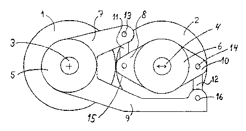
A roller press comprising two rollers (1, 2) which rotate in opposite
rotational directions, the rollers being driven via two
gear units (5, 6) mounted on the roller shafts (3, 4), and having means for
counterbalancing the oppositely-directed torques aris-
ing in the gear units in the form of a torque reaction system (7-12),
eliminating the need for a torque absorption mechanism att-
ached to the machine frame of the roller press.


Claims

Note: Claims are shown in the official language in which they were submitted.

5
CLAIMS:
1. A roller press comprising two rollers (1,2) which have a
variable nip width and which are driven in opposite rotational
directions via two reduction gear units (5,6) each of which is
mounted on a separate shaft (3,4) for a respective one of the
rollers; the gear units having a torque reaction system comprising
two pairs of arms (7,9;8,10) each pair being rigidly connected to a
respective one of the gear units, and each arm of one pair being
coupled with a respective one of the arms of the other pair so as to
transmit therebetween torque-generated forces acting substantially
perpendicularly to the plane containing the roller axes, while
permitting mutual reciprocal movement of the rollers in that plane.
2. A press according to claim 1, wherein couplings between the arms
comprise a pair of rigid connecting rods (11,12), each of which is
pivotally connected at its ends to respective arms of respective
ones of the gear units.
3. A roller press according to claim 1, wherein couplings between
the arms comprise a pair of planar slide bearings (17,18), each
mounted between two arms, one from each gear unit.
4. A roller press according to claim 1, wherein couplings between
the arms comprise a pair of planar roller bearings (17,18), each
mounted between two arms, one from each gear unit.

Description

Note: Descriptions are shown in the official language in which they were submitted.


~'~ 92/13639 P~['/EP92/00141
1~~~Q~~~~
1io11er Press
The present invention relates to a roller press of the
kind (hereinafter referred to as of the kind described)
comprising two rollers which have a variable nip width and
which are driven in opposite ratational directions via twa
reduction gear units each of which is mounted on a separate
shaft for a respective one of the rollers, the gear units
having a torque reaction system,
In known roller presses of the above kind, each gear
unit is normally connected to the foundation or the machine
frame by means of a single torque arm. This, however,
involves the disadvantage that the torques are transformed
into reaction forces, causing high loads in the gear unit
~.5 bearings and bending of the roller shafts.
Therefore, owing to the significant torques and torque
variations generally occurring in roller presses, it is
advantageous to utilize a dual arm reaction system with the
capability of directly balancing 'the forgoes without
generating reaction forces causing high loads in the
bearings.
A roller press of the this kind is known from
EP-A-0280897 where the ~torques occurring in the two gear
units are substantially balanced agaanst each other, so
that any differential torque, arising as a result of a
numerical difference.bet~r~en the two forgoes, is absorbed
by a single torque arm fi~c~d between ane gear unit and the
foundation or the machine frame of the roller press: This
reaction system is of a relatively complex construction in
that it xequirea a torsion shaft,.supported by bearings an
the fixed gear unit, and pivotally connected at each end to
a coupling means, which in turn is connected to the movable
gear unit. Each coupling means for the displaceable gear
unit is connected to the torsion shaft by means of a
coupling arm so that the torque from the displaceable gear
unit produces appositely-directed torsion of the torsion
shaft. As a consequence thereof, the system is relatively

~'O 92/ 1339 ~~, ~ ~ ~ p
C.T/W'92/00141
2
expensive, both in terms of manufacture and maintenance.
Another inherent weakness of that system is the need for an
additional torque arm which is attached to the foundation
or the machine frame in order to absorb a potential
differential torque arising as a result of a difference in
torques in the twa gear units.
It is the object of the invention to provide a
reaction system for a roller press of the kind described
whereby the need far a torque absorption mechanism attached
to the machine frame is eliminated, with the added benefit
that the system is simple and cheap to manufacture and
maintain in comparison with the known system.
According to the invention-, this object is achieved if
the torque reaction system of a roller press of the kind
described comprises two pairs of arms, each pair being
rigidly connected to a respective one of the gear units,
and each arm of one pair being coupled with a respective
one of the arms of the other pair so as to transmit
therebetween torque-generated forces acting substantially
perpendicularly to the plane containing the roller axes,.
while permitting mutual reciprocal movement of. the rollers
in that plane.
~y providing the arms on the gear units in such a
manner that the couplings only have the capability to
absorb forces in a direction substantially perpendicular to
the plane, which includes the rcatati.onal axes of the
rollers, the effect is achieved that a differen~.ial torque,
if any, can be absarbed by the shaft bearings for the
roller shafts. This is due to the fact that, by virtue of
the special construction according to the invention, a
potential differential torque is transformed into a pure
push-pull force component which, without any significant
increase in the load capacity of the bearings, can be
absorbed by the latter.
The couplings may comprise a pair of rigid connecting
rods, each of which is pivotally connected at its ends to
respective arms of respective ones of the gear units.

'~'O 92/13639 pCT/EP92/OOlal
Alternatively, the couplings may comprise a pair of
planar slide or roller bearings, each mounted between two
arms, ane from each gear unit.
The invention is now described by the way of example
with reference to the accompanying drawings in whiehs-
Fig. 1 is a side view of a first example of a roller
press according to the invention having a torque reaction
system in which the couplings comprise connecting rods;
Fig. 2 is a plan of the example illustrated in Fig. 1;
Fig. 3 shows a second example of a roller press
according to the invention having a torque reaction system
in which the couplings comprise slide bearings or roller
bearings; and,
Fig. 4 is a side view of a third example of a roller
press according to the invention in which the couplings
comprise connecting rods.
In the figures, which are diagrammatic, all parts of
the roller press of no significance to the present
invention are omitted.
The roller press shown in Figs. 1 and 2 comprises two
rollers 1, 2, of which the axis of one roller 1 is
stationary, whereas the second roller 2 is movable
relatively to the first roller 1, being urged against the
latter by means of for example hydraulic cylinders, not
shown. The rollers are rotatable in opposite directions by
means of their separate roller shafts 3, 4, x~hich are
rotably mounted in the machine frame of the roller press
(not shown), and are driven via two gear units 5, 6 mounted
on separate roller shafts. Each gear unit S, C has two
rigid arms 7, 9, and 8, 10 respectively, the arms being
inter-connected in pairs by means of cannecting rods 11, 12
pivotally mounted on the arms at 13, 15, and 14, 16
respectively.
The gear units with the arms 7, 9 and 8, 10
respectively connected in pairs to the connecting rods 11,
12, will act as a reaction system for the torques acting
upon the gear units.

W~ 92/13b39 ,~ ~ ~~ 'PC'1('/EP92/OOl~i
In operation, the torques developed in the gear units
as a consequence of the frictional force between the
rollers will hence counterbalance each other. If the
torques in the gear units 5, f are of the same numerical
size, the force iri the Connecting rods 1l, J.2 will be equal
to the torque divided by the distance between the
connecting rods. However, in event of a difference,
normally minor, between the torques, such difference will
be equalized by reactions in the roller shafts, with the
reactions being equal to the difference between 'the torques
divided by the distance between the roller axes.
Fig. 3 shows a different reaction system for a roller
press which is identical to that illustrated in Fig. 1 and
2. In this example, the couplings comprise plane slide
and/or roller bearings 17, 18. The details incorporated in
the construction of bearings axe not shown in the figure,
but they have to be so configured that they permit movement
of the roller 2 with gear unit 4 in direction towards and
away from roller 7L with the gear unit 3. This movement of
the roller 2 is shown in Fig. 1, 3 and 4 by means of a
double arrow.
Another example of a reaction system according to the
invention is shown in Fig. 4. This arrangement is
especially preferred since it eliminates the space problem
which may occur when mounting the coupling between the gear
units 5, 6 as according to the former examples. By
providing the connections between the arms at a distance
from the roller shafts relative to the mutual line of
contact between the rollers, this eliminates the need for
more space between the gear units, which space is often
restricted.
The couplings for the example shown in Fig. 4 do not
necessarily.ineorporate connecting rods, as shown, but may
also be substituted by slide or roller bearings.

Representative Drawing
A single figure which represents the drawing illustrating the invention.
Administrative Status

2024-08-01:As part of the Next Generation Patents (NGP) transition, the Canadian Patents Database (CPD) now contains a more detailed Event History, which replicates the Event Log of our new back-office solution.

Please note that "Inactive:" events refers to events no longer in use in our new back-office solution.

For a clearer understanding of the status of the application/patent presented on this page, the site Disclaimer , as well as the definitions for Patent , Event History , Maintenance Fee  and Payment History  should be consulted.

Event History

Description Date
Inactive: Expired (new Act pat) 2012-01-23
Letter Sent 2010-02-23
Inactive: Office letter 2010-01-27
Inactive: IPC from MCD 2006-03-11
Grant by Issuance 2003-06-10
Inactive: Cover page published 2003-06-09
Pre-grant 2003-03-25
Inactive: Final fee received 2003-03-25
Notice of Allowance is Issued 2002-10-01
Letter Sent 2002-10-01
Inactive: Approved for allowance (AFA) 2002-09-13
Amendment Received - Voluntary Amendment 2002-06-06
Inactive: S.30(2) Rules - Examiner requisition 2002-02-26
Amendment Received - Voluntary Amendment 1998-12-01
Inactive: RFE acknowledged - Prior art enquiry 1998-11-05
Inactive: Application prosecuted on TS as of Log entry date 1998-11-04
Inactive: Status info is complete as of Log entry date 1998-11-04
Request for Examination Requirements Determined Compliant 1998-10-23
All Requirements for Examination Determined Compliant 1998-10-23
Application Published (Open to Public Inspection) 1992-08-20

Abandonment History

There is no abandonment history.

Maintenance Fee

The last payment was received on 2002-12-17

Note : If the full payment has not been received on or before the date indicated, a further fee may be required which may be one of the following

  • the reinstatement fee;
  • the late payment fee; or
  • additional fee to reverse deemed expiry.

Patent fees are adjusted on the 1st of January every year. The amounts above are the current amounts if received by December 31 of the current year.
Please refer to the CIPO Patent Fees web page to see all current fee amounts.

Owners on Record

Note: Records showing the ownership history in alphabetical order.

Current Owners on Record
F.L. SMIDTH & CO. A/S
Past Owners on Record
KNUD TONI ANDERSEN
Past Owners that do not appear in the "Owners on Record" listing will appear in other documentation within the application.
Documents

To view selected files, please enter reCAPTCHA code :


To view images, click a link in the Document Description column. To download the documents, select one or more checkboxes in the first column and then click the "Download Selected in PDF format (Zip Archive)" or the "Download Selected as Single PDF" button.

List of published and non-published patent-specific documents on the CPD .

If you have any difficulty accessing content, you can call the Client Service Centre at 1-866-997-1936 or send them an e-mail at CIPO Client Service Centre.


Document
Description 
Date
(yyyy-mm-dd) 
Number of pages   Size of Image (KB) 
Claims 1994-05-13 1 45
Abstract 1995-08-16 1 72
Claims 2002-06-05 1 33
Description 1994-05-13 4 198
Abstract 2002-09-22 1 72
Drawings 1994-05-13 2 32
Representative drawing 1999-02-09 1 14
Representative drawing 2002-02-24 1 10
Reminder - Request for Examination 1998-09-23 1 116
Acknowledgement of Request for Examination 1998-11-04 1 172
Commissioner's Notice - Application Found Allowable 2002-09-30 1 163
Correspondence 2003-03-24 1 28
PCT 1993-02-24 12 346
Correspondence 2010-01-26 1 14
Correspondence 2010-02-22 1 13
Correspondence 2010-02-01 1 36
Fees 1996-12-17 1 65
Fees 1995-12-19 1 62
Fees 1994-12-28 1 69
Fees 1993-12-16 1 65