Language selection

Search

Patent 2090583 Summary

Third-party information liability

Some of the information on this Web page has been provided by external sources. The Government of Canada is not responsible for the accuracy, reliability or currency of the information supplied by external sources. Users wishing to rely upon this information should consult directly with the source of the information. Content provided by external sources is not subject to official languages, privacy and accessibility requirements.

Claims and Abstract availability

Any discrepancies in the text and image of the Claims and Abstract are due to differing posting times. Text of the Claims and Abstract are posted:

  • At the time the application is open to public inspection;
  • At the time of issue of the patent (grant).
(12) Patent: (11) CA 2090583
(54) English Title: LEADING EDGE PROTECTION FOR FAN BLADE
(54) French Title: DISPOSITIF DE PROTECTION DE BORD D'ATTAQUE DE PALES DE VENTILATEURS
Status: Expired and beyond the Period of Reversal
Bibliographic Data
(51) International Patent Classification (IPC):
  • F01C 05/04 (2006.01)
  • F04D 19/00 (2006.01)
  • F04D 29/28 (2006.01)
  • F04D 29/38 (2006.01)
(72) Inventors :
  • MONROE, ROBERT C. (United States of America)
(73) Owners :
  • HUDSON PRODUCTS CORPORATION
(71) Applicants :
  • HUDSON PRODUCTS CORPORATION (United States of America)
(74) Agent: SMART & BIGGAR LP
(74) Associate agent:
(45) Issued: 1997-11-18
(22) Filed Date: 1993-02-26
(41) Open to Public Inspection: 1993-12-27
Examination requested: 1993-02-26
Availability of licence: N/A
Dedicated to the Public: N/A
(25) Language of filing: English

Patent Cooperation Treaty (PCT): No

(30) Application Priority Data:
Application No. Country/Territory Date
904,935 (United States of America) 1992-06-26

Abstracts

English Abstract


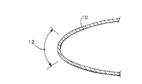
A protection element containing a spring steel strip is bent
to have a greater curvature than the curvature at the leading
edge of a fan blade. This protection element is then fixed to
the leading edge of the fan blade over an area of maximum
erosion. Rubber or another elastomer can be extruded over the
strip before or after it is fixed to the fan blade or the strip
can incorporate an outer hardened layer to resist erosion.
Attachment of the strip to the blade is advantageously
accomplished using rivets or screws at spaced locations along the
blade and at the leading edge of the blade.


French Abstract

La présente invention vise un élément protecteur pour aube de ventilateur, constitué d'une bande en acier à ressort dont le rayon de courbure est supérieur à celui du bord d'attaque de l'aube. Cet élément est fixé sur la portion du bord d'attaque où le risque d'érosion est le plus élevé. Un revêtement de caoutchouc ou d'un autre élastomère peut être extrudé sur l'élément protecteur, avant ou après sa mise en place sur l'aube, ou encore l'élément peut comporter un revêtement extérieur durci intégré. Selon une version privilégiée, l'élément protecteur est fixé sur l'aube au moyen de rivets ou de vis disposés le long de cette dernière et sur son bord d'attaque.

Claims

Note: Claims are shown in the official language in which they were submitted.


-6-
THE EMBODIMENTS OF THE INVENTION IN WHICH AN EXCLUSIVE
PROPERTY OR PRIVILEGE IS CLAIMED ARE DEFINED AS FOLLOWS:
1. An edge protection arrangement for a fan blade having a
leading edge with an area of maximum erosion and a selected
curvature, comprising:
a. a continuous strip of spring steel bent to a greater
curvature than the curvature of the fan blade leading edge
and fixed over the area of maximum erosion on the fan blade
leading edge; and
b. anti-erosion means on at least one surface of said
spring steel strip for preventing erosion of the leading
edge.
2. An arrangement according to Claim 1, wherein said
anti-erosion means comprise an elastomer extruded over said
strip.
3. An arrangement according to Claim 2, including a plurality
of spaced holes in said strip and a plurality of connectors
extending through said holes for fixing said strip to the fan
blade.
4. An arrangement according to Claim 1, including a plurality
of spaced holes in said strip and a plurality of connectors
extending through said holes for fixing said strip to the fan
blade.
5. An arrangement according to Claim 4, wherein said
anti-erosion means comprise a hardened outer surface on said
strip facing outward away from the blade.
6. An arrangement according to Claim 1, wherein said
anti-erosion means comprises a hardened outer surface on said
strip facing outward away from the blade.

-7-
7. An arrangement according to Claim 6, including a plurality
of holes through said strip and a rivet in each said hole for
fixing said strip to the leading edge of the blade.
8. A method of protecting the leading edge of a fan blade
having an area of maximum erosion and a selected curvature,
comprising the steps of:
a. bending a continuous strip of spring steel to have a
greater curvature than the curvature of the leading edge of
the fan blade;
b. applying anti-erosion means over at least one surface
of said strip for preventing erosion of this said surface;
c. pressing said strip onto the blade by at least partly
biasing said strip so that when released it tightly grips an
outer surface of the blade; and
d. permanently fixing said strip to the leading edge of
the blade.
9. A method according to Claim 8, wherein said anti-erosion
means comprises an elastomer extruded over said strip before it
is fixed to the blade.
10. A method according to Claim 9, wherein said elastomer is
rubber.
11. A method according to Claim 10, including providing a
plurality of spaced holes along said strip and fixing said strip
to the hollow blade using rivets or screws.
12. A method according to Claim 10, wherein said anti-erosion
means comprise a hard outer layer applied to said strip on the
surface of said strip which is away from the blade.

Description

Note: Descriptions are shown in the official language in which they were submitted.


CASE 5256
209~5~3
~k~V~U LEADING EDGE ~K~ ON FOR FAN BLADE
FIELD AND BACKGROUND OF THE lNV~NllON
Steam generating units or petrochemical process plants
require large numbers of wet cooling towers to cool water used in
steam condensing or other heat ~Ych~nge applications. This water
is typically cooled by evaporation, such as by co-mingling with
air supplied by large multi-bladed fans. In this process, some
water droplets are entrained in the air and come into contact
with the leading edges of the fan blades. These fan blades will
generally be moving at a very high velocity, typically 125 mph at
the outer-most radius of the blade, and thus, over time, damage
to these blades will occur.
The most troublesome problem with the fans used in these wet
cooling towers is leading edge erosion which is caused by impact
with the water droplets entrained in the air stream. Severe
erosion by such impact can result in the loss of these fan blades
costing $1,000.00 or more in repl~c ~ ~ costs. One technique
for p~el.~ing such erosion is to apply a rubber "boot" to the
leading edge of each blade in order to absorb the impact energy
of colliding with the droplets. The cost of this rubber boot is
approximately ~200 to ~500 per blade with this cost including
about four hours labor for installation. Thus, when considering
the vast number of blades to be corrected, the cost and effort
involved is quite substantial.
There is also an ongoing debate as to whether the erosion
problem is due to faults in the blade or due to excessive water

CASE 5256
-2- ~ n ~ 3
droplets in the air which compounds the difficulty of correcting
the resultant problem.
SUMMARY OF THE lNv~NllON
An object of the present invention is to provide improved
leading edge protection for fan blades which is inexpensive and
effective in reducing leading edge corrosion. The low cost and
effectiveness of the invention avoids the debate concerning
whether erosion is due to faults in the blade or excessive drift
since the invention can be economically applied to solve the
problem without addressing which factor causes the erosion.
According to the present invention, a thin gage, continuous,
stainless steel spring strip is shaped to conform to the leading
edge profile of the blade. Holes are punched at uniform
distances along the center of the strip and a coating of rubber
or other elastomer is extruded around the strip with the thickest
~i ~n~ion at the point of -~; erosion on the blade. The
holes are utilized to fasten the strip to the leading edge of the
blade in a quick, economical and effective manner.
Accordingly, another object of the present invention is to
provide improved leading edge protection for fan blades which is
simple in design, rugged in construction and economical to
manufacture and install.
The various features of novelty which characterize the
invention are pointed out with particularity in the claims
annexed to and forming a part of this disclosure. For a better
understAn~ing of the invention, its operating advantages and
specific objects attained by its uses, reference is made to the

C~S~ 5256
-3~
accompanying drawings and descriptive matter in which the
preferred ~mbodiments of the inYentic)n are illustrated.
BRIEF DESCRIPTION OF THE DRAWINGS
Fig. 1 is a partial sectional view of the leading edge of a
fan blade illustrating the area of malximum erosion.
Fig. 2 is an exploded view showing the leading edge of the
fan blade and illustrating the leading edge protection of the
present invention before it has been installed.
Fig. 3 is the leading edge of the fan blade with the edge
protection of the present invention installed.
Fig. 4 is a view similar to Fig. 3 showing an alternate
embodiment of invention.
DESCRIPTION OF THE PREFERRED EMBODIMENTS
Referring to the drawings, and in particular Fig. 1, there
is shown a typical leading edge construction of fan blade 10.
The leading area of approximately 1 inch in arcuate length at 12,
is exposed to ~i erosion during the useful life of blade 10.
Fig. 2 illustrates the edge protection member of the
invention which is generally designated 20. It consists of an
elongated continuous thin gage stainless steel spring strip 22
surrounded by an extruded covering of rubber or other elastomer
24. The curvature of this stainless steel strip 22 is selected
to match or be greater than the curvature of the leading edge of
blade 10 so that with protection member 20 installed, spring
steel strip 22 will squeeze or be biased tightly against and
thereby grip the leading edge of blade 10. Holes 26 (one shown)
are also punched through protection --h~r 20 at spaced locations
along its length, this length being normal to the plane of Fig. 2

CASE 5256
~ ~ Q '~
Holes 26 can be punched into sp~ring steel 22 before rub~er
24 is extruded, followed by pilot hoLes or alignment markings on
the surface of the rubber to indicate the location of the
underlying holes. ~lternatively, holes 26 may be punched after
rubber 24 is extruded over stainless steel strip 22, whichever is
desired. The area of high erosion protection 14 provided by
member 20 is selected to match the area of high erosion 12 on
blade 10, with the width of strip 22 (defined by reference
numeral 16) on opposite sides of this high corrosion area, being
selected to be approximately 2 to 3 inches.
Fig. 3 illustrates the installed position of protection
member 20 on blade 10. Stainless steel strip 22 is expanded
slightly to accommodate the curvature of blade 10 and at the same
time firmly hold itself and extruded rubber coating 24 against
blade 10 to avoid rattling or any other displacement. A
connector 30, for example a blind monel rivet or a screw, is
fastened through holes 26 and the corresponding aligned holes in
the leading edge of blade 10. Ideally, these holes 26 would be
drilled during blade assembly to provide an entrance for the
rivet through the blade laminate. Advantageously, holes 26 are
provided every 8 to 10 inches (or so) on center along the radial
length of blade 10 which may be 16 feet or more. Despite the
drilling of such holes 26, it should be understood that this
operation does not com~r~ i~e the strength of blade 10.
Fig. 4 illustrates a second embodiment of the invention
wherein edge protection member 20 comprises a stainless steel
strip 32 fastened by rivet 34 at spaced locations along the axial
length along blade 10. Stainless steel spring 32 is configured

C.~SE 525~i
-5- 2 ~ 3
with a hard facing of known materia,l 36 on its outer surface.
Titanium nitride or any other known hardened layer material can
qualify as layer 36. Other similar variations are also equally
likely.
According to the present invention, edge protection member
20 can be installed at a rate of approximately 30 to 45 minutes
per blade. This is compared to the four hours or more of
installation time normally required to install the previously
used boot construction. Strips 22 or 32 of edge protective
member 20 can also be constructed to have a r~;rllr thickness at
the point of r~ erosion and to have a greater curvature than
blade 10 so that when installed, member 20 closely hugs the outer
surface of blade 10. An adhesive may also be applied between
edge protection member 20 and blade 10 to further affix edge
protection member 20 to blade 10 if need be.
With proper spacing between holes 26 in protection member 20
and blade 10, the invention can be advantageously applied to
blades having a radial length of 16 feet or more, as well as to
blades having a length less than 16 feet.
While the specific ~ ho~i -nts of this invention have been
shown and described in detail to illustrate the application of
the principles of the invention, it will be understood that the
invention may be - ho~ied otherwise without departing from such
principles.

Representative Drawing
A single figure which represents the drawing illustrating the invention.
Administrative Status

2024-08-01:As part of the Next Generation Patents (NGP) transition, the Canadian Patents Database (CPD) now contains a more detailed Event History, which replicates the Event Log of our new back-office solution.

Please note that "Inactive:" events refers to events no longer in use in our new back-office solution.

For a clearer understanding of the status of the application/patent presented on this page, the site Disclaimer , as well as the definitions for Patent , Event History , Maintenance Fee  and Payment History  should be consulted.

Event History

Description Date
Inactive: IPC from MCD 2006-03-11
Time Limit for Reversal Expired 2005-02-28
Letter Sent 2004-02-26
Grant by Issuance 1997-11-18
Pre-grant 1997-05-28
Notice of Allowance is Issued 1997-04-22
Application Published (Open to Public Inspection) 1993-12-27
All Requirements for Examination Determined Compliant 1993-02-26
Request for Examination Requirements Determined Compliant 1993-02-26

Abandonment History

There is no abandonment history.

Fee History

Fee Type Anniversary Year Due Date Paid Date
Final fee - standard 1997-05-28
MF (patent, 5th anniv.) - standard 1998-02-26 1998-02-04
MF (patent, 6th anniv.) - standard 1999-02-26 1999-02-10
MF (patent, 7th anniv.) - standard 2000-02-28 2000-02-02
MF (patent, 8th anniv.) - standard 2001-02-26 2001-02-01
MF (patent, 9th anniv.) - standard 2002-02-26 2002-01-31
MF (patent, 10th anniv.) - standard 2003-02-26 2003-01-17
Owners on Record

Note: Records showing the ownership history in alphabetical order.

Current Owners on Record
HUDSON PRODUCTS CORPORATION
Past Owners on Record
ROBERT C. MONROE
Past Owners that do not appear in the "Owners on Record" listing will appear in other documentation within the application.
Documents

To view selected files, please enter reCAPTCHA code :


To view images, click a link in the Document Description column. To download the documents, select one or more checkboxes in the first column and then click the "Download Selected in PDF format (Zip Archive)" or the "Download Selected as Single PDF" button.

List of published and non-published patent-specific documents on the CPD .

If you have any difficulty accessing content, you can call the Client Service Centre at 1-866-997-1936 or send them an e-mail at CIPO Client Service Centre.


Document
Description 
Date
(yyyy-mm-dd) 
Number of pages   Size of Image (KB) 
Abstract 1994-02-25 1 15
Claims 1994-02-25 2 63
Drawings 1994-02-25 2 23
Description 1994-02-25 5 171
Representative drawing 1997-11-16 1 4
Maintenance Fee Notice 2004-04-21 1 173
Fees 1997-02-13 1 28
Fees 1995-01-19 1 26
Fees 1996-01-23 1 27
Prosecution correspondence 1993-02-25 3 138
Correspondence related to formalities 1997-05-27 1 41