Note: Descriptions are shown in the official language in which they were submitted.
CA 02090771 2001-06-26
27791-4
COMPOSITE MATERIAL AND METHOD FOR PRODUCING THE SAME
Technical Field
This invention relates to composite material obtained
from different materials in a two-layer construction and
method for producing the same, in particular composite
material suitable for making non-lubricant bearings having
relative small diameter. consisting of metal plate covered
with fluororeain on its inner side surface.
Background of the invention
In general, in rotary parts and sliding parts of
various equipments having small sizes, such as tape-
recorder, video player and the like, frequent use is made
of non-lubricant bearings called "dry-bearings" which do
not contain lubricant, due to the absence of contamination
1!~ caused by lubricant, the simplicity of their construction
and other reasons. In particular, non-lubricant bearings
using suitable bearing menber; for instance, fluororesin at
their rotary or sliding members are preferred owing to the
low friction coefficient of the materials used, 1.e.
20 fluororesin.
Fig.lO is a cross-sectional view of a heretofore known
non-lubricant bearing 1. This non-lubricant bearing 1
comprises a round bar or pipe shaped member 2 of
polytetrafluo:roethylene (called hereinbelow PTFE) having
2!~ low friction coefficient, the member being machined into a
- 1 -
CA 02090771 2001-06-26
27791-4
substantially cylindrical form of determined sizes and
shape. Such non-lubricant bearing 1 must have an increased
wall-thicknes~c due to the low mechanical strength of PTFE
forming the member 2, so that the bearing 1 requires for
example a thickness move than 1.5 mm of wall-thickness for
3 mm of j.nner diameter thereof. Therefore, non-lubricant
bearing 1 of larger diameter requires more quantity of PTFE
of higher price, which increases the manufacturing cost
thereof. When using the bearings at high PV values,
deformation of the mass of PTFE becomes larger due to the
large wall-thickness thereof. Further, heat generated from
the relative movements between the non-lubricant bearing 1
and members such as shaft mounted therein is accumulated
within the mass of PTFE, the heat causing a thermal
1r; expansion of the bea ring 1, so that a large clearance
between non-:Lubricant tearing 1 and corresponding shaft has
been inevitable.
Further, the heat generated from the relative
movements between non-lubricant bearing 1 and corresponding
shaft causes the softening of PTFE as well as increase of
wear thereof" thereby to shorten the life of non-lubricant
bearing 1.
For eliminating the problems as described above, non-
lubricant bearing 4 made from composite material 3 as shown
in Figs.ll i:.o 13 is used. Such a non-lubricant bearing 4
uses composite material 3 which comprises plane steel plate
5 and a layer or sheet 6 of PTFE adhering to the steel
plate 5. The composite material 3 is then machined or
- 2 -
CA 02090771 2001-06-26
27791-4
punched into determined sizes and shaped into round form,
thereby to obtain a substantially cylindrical form of non-
lubricant bearing 4 having a slit 7. In such a non-
lubricant bearing 4 made from composite material 3,
adhesives of epoxy resins having high thermal resistance
and high adhesive property are used for joining PTFE layer
6 onto steel plate 5. However, the joining layer 8 using
epoxy resin is separata_d owing to the low elongation of 1-2
of epoxy resin used when shaping the composite material
3 into round forms Eor manufacturing non-lubricant bearing
4 having small radius curvature, i.e. of small diameter.
In another type of non-lubricant bearing 14 as shown
in Fig. l4, inner member 12 of bearing member 11 using
fluororesin .and the like shaped into cylindrical form with
a predetermined interference is fitted into outer member 10
of tube formed from metal materials 9 so as to obtain a
composite material 13, which is then machined into
determined form of non-lubricant bearing 4. In order to
increase the productivity, long lengths of the composite
2~~ material 13 consisting of the inner member 10 and the
outer member 12 of 7_ong lengths, for example 2-3 meters,
are fed continuously into working machine such as automatic
lathe for cuti:.ing and other working thereof.
However, the fitting operation of the outer member
2!~ 10 into the inner member 12 having a predetermined
interference has been very difficult except for these
members having short 7Lengths and even almost impossible for
long lengths of members. Further, adhesives applied on the
- 3 -
CA 02090771 2001-06-26
27791-4
surface of the members are apt to be separated in the
fitting operation.
Accordingly, in other manufacturing process, the outer
member 10 i~; fitted with a play onto the inner member 12
and the assembly thus obtained is subjected to a drawing to
produce integral material 13.
However, in this process, a camber of lOmm per 1 m of
length of the composj_te material 13 is generated in the
drawing operation. When the resulting composite material 13
having the camber is subjected to a working such as
cutting, the one end portion thereof is chucked and
rotated, while the other end thereof showing the camber is
caused to rotate in an eccentric manner thereby to cause
lei vibration of the composite material 13. The resulting
vibration is transferred to the cutting edge, so that a
high accuracy of working can not be maintained. For
obtaining a higher accuracy, it is necessary to cut the
composite mai:.erial into short lengths, which cause however
a dispersion of quality and an increase of manufacturing
cost, so that a higher working techniques and devices are
needed.
Further, when the non-lubricant bearings 14 are used
as tape-guides roller 1_n the video player and the like, a
2!~ higher accuracy is needed for manufacturing the same so
that it has been hardly possible to use long materials due
to the above mentioned reasons, which brings about a more
complicated working process and additional economical
- 4 -
CA 02090771 2001-06-26
27791-4
burden. In addition to such an additional economical burden,
the high price of fluororesin used as raw materials increases
considerably t:he cost of non-lubricant bearings thus obtained.
As a result, i=luororesi.n can not be used in practice for non-
lubricant bearings, so that pol.yacetal resin has been used in
place of fluororesin ir-L many cases. However, when using
polyacetal as materials of bearings 11 for example in the
mechanism such as video player for business use which rotates
in very high velocities, stick slips may be caused with
vibration and noises, with the result that the inner member 12
will get out _Erom the cuter member 10.
SUMMARY OF THE INVENTION
It :is therefore an essential object of this invention
to create reliable composite material having relatively simple
construction <~nd consisting of outer member and inner member
securely fixed with each other for eliminating the
disadvantages of prior techniques as described above and the
method for obvaining the same.
The present invention provides a composite material
consisting of an inner cr~e~mber fixed onto an inner surface of an
annular outer member, wherein the inner surface of the outer
member and an outer surface of the inner member are opposed to
each other with a gap between them, while at least one of the
inner surface and the outer surface has a plurality of
protrusions projecting to the other surface, and the outer and
inner members are joined. together by means of a joining means
placed in the gap between the inner surface and the outer
surface.
5
CA 02090771 2001-06-26
27791-4
Preferably, the outer member and the inner member
have respectiz~e lengths.
Also preferably, at least one of the outer member and
the inner member is made of a metal and the outer member is of
a fluororesin.
Another aspect of the present invention provides a
method for obt:aining a c«mposite material consisting of an
inner member faxed into ~~n annular outer member. According to
a first major embodiment, this process comprises the steps of:
forming independently the outer member and the inner
member, with an outer surface diameter of the inner member
being a little smaller than an inner surface diameter of the
outer member;
forming a plur;~lity of protrusions on at least one of
the inner surface and the outer surface;
inserting the inner member into the outer member so
as to form a chap between the opposing surfaces of the inner and
outer members; and
fil7_ing a joining means into the gap thereby to join
the inner and outer members.
A second major embodiment. of the method for obtaining
the composite material consisting of the inner member fixed
into the annu7_ar outer member according to the invention
comprises the steps of:
forming independently the outer member and the inner
member, with ~~n outer surface diameter of the inner member
6
CA 02090771 2001-06-26
27791-4
being a little smaller than an inner surface diameter of the
outer member;
forming a plurality of protrusions on at least one of
the inner sur:Eace and the outer surface;
coating joining means on at least one of the inner
and outer sur:Eaces;
insf=_rting the inner membE=r into the outer member; and
joining the inner and outer members into an integral
structure by means of the joining means placed between the
members.
Pre:~erably, at least one of the outer and inner
members is of metal and the other member is of fluororesin.
Whe:z manufacturing the composite material according
to the invention by the method ment=ioned above, it is possible
to easily mount the inner member onto the outer member to form
a secure inte~~ral construction, thereby eliminating the
disadvantages of needing any special techniques and apparatuses
and thus increasing the manufacturing cost.
7
CA 02090771 2001-06-26
27791-4
BRIEF DESCRIP'L'ION OF THE DRAWINGS
For a better understanding of the present invention,
the scope of which will. be pointed out in the appended claims,
reference may be made to the following detailed descriptions of
exemplary embodiments thereof, taken in
8
conjunction with. the accompanying drawings, in which:
Fig.l is a partly broken-out perspective view of an
embodiment of composite material according to the invention
used in a non-lubricant bearing;
Fig.2 is cross-sectional view of a part of the non-
lubricant bearing shown in Fig. l;
Fig.3 is a longitudinal section view taken along the
line A-A of Fig.2;
Fig.4 is a longitudinal section view showing a part of
a molding apparatus for the composite material according to
the invention;
Fig.5 is a large-scale cross-sectional view taken
along line B-B of Fig.4 and showing the essential part of
mold for the inner member of composite material according
to the invention;
Fig.6 is a large-scale cross-sectional view of a part
of a non-lubricant bearing wherein the inner member is
inserted into the outer member in the first embodiment of
the method for obtaining the composite material according
to the invention;
Fig.7 is a crass-sectional view showing an example
according to the second embodiment of the method wherein
joining means is applied on the inner member of composite
- 9 -
~~~~v"~
material;
Fig.8 is a cross-sectional view showing an example
according to the second embodiment of the method wherein
the inner member is inserted into the outer member;
Fig.9 is a cross-sectional view showing another
example according to the second embodiment of the method
wherein the joining means is applied on the inner member;
Fig.lO is a longitudinal section view of heretofore
known typical non-lubricant bearings;
Fig.ll is a perspective view for illustrating the
manufacturing process of heretofore known composite
material;
Fig. l2 is a longitudinal section view of another non-
lubricant bearing using the composite material shown in
Fig.ll;
Fig. l3 is a cross-sectional view of non-lubricant
bearing of Fig. l2;
Fig. l4 is a longitudinal section view of another non-
lubricant bearing using other heretofore known composite
material.
Detailed Description of the preferred embodiment
The embodiments of invention are described more in
- 10 -
CA 02090771 2001-06-26
27791-4
detail with reference to Figs.l-9 hereinbelow.
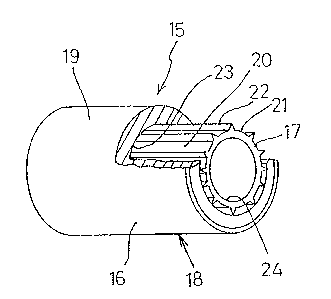
Figs.l-3 show an embodiment of non-lubricant bearing
using the composite material according to the invention,
Fig.l showing a partly broken-out perspective view of a
part of said non-lubricant bea ring, Fig.2 a cross-sectional
view thereof and Fig.3 a longitudinal section view thereof
taken along A-A line of Fig.2.
As shown in these figures, the non-lubricant bearing
is made from composite material 18 consisting of outer
10 member 16 and inner member 17 joined together. The outer
member 16 is formed into a cylindrical form from any
desired metal. materials 19 such as stainless steal in this
embodiment. The inner member 17 is formed into
substantially cylindrical form from fluororesin layer 20
15 such as PTFE with or without a suitable quantity of filler
or fillers blended therein for the purpose of increasing
its friction resistance, the fillers being for example
glass fiber, carbon, graphite, molybdenum, carbon-fiber and
the like or their combinations. A suitable gap ~ is
formed between the inner surface 23 of outer member 16 and
the outer surface of inner member 17 as shown in Fig.2.
Further, a plurality, for example 12 in this embodiment, of
projections :?2 each extending in the axial direction and
having a cross section of triangle protruding outward in
2~~ the radial direction a:re formed on the outer surface 21 of
the inner member 17. The maximum outer diameter d00 of a
circle taken along the apexes of the triangles of the
protrusions 22 is substantially the same as the inner
- 11 -
CA 02090771 2001-06-26
27791-4
diameter D00 of the nner surface 23 of the outer member
16. A surface 24 for relative movement such as rotation,
sliding and oscillation with respect to shaft not shown and
the like is provided on the inner surface of the inner
member 17. Further, the gap ~ is filled with joining
means 25 such as adhesives, PTFE resin in this embodiment.
This joining means s'.5 secures the outer member 16 and
inner member 17 together to form a solid structure of
composite material 18. The cross section of the
1(1 projections 22 is not limited to a triangle, but can be
semi-circular.. A plurality of projections 22 are used
herein,but the number thereof is not limited to any
specific number.
The first embodiment of the process for obtaining the
composite material as described above is now explained with
reference to F'igs.4-6.
Fig.4 is a longitudinal section view showing a part of
a molding apparatus of the inner member, Fig.S an enlarged
cross-sectional view taken along line B-B of Fig.4, and
Fig.6 an enlarged cross-sectional view of a part of outer
member and inner member assembled together, respectively.
First, t:he outer member 16 is formed into a pipe of
long length i.n the orde r of 2.5 m having outer diameter 4.1
mm and inner diameter D00 of 3 mm or a little larger through
any well known process, for example by drawing suitable
material such as seamless pipe or the seam pipe of
stainless stea:L and the like.
- 12 -
CA 02090771 2001-06-26
27791-4
Secondly" the inner member 17 is made by a paste
extruding process through a suitable molding apparatus 26
and mold 27 as shown in Fig.4 and Fig.5. More specifically,
the inner member 1.7 is manufactured by extruding
fluororesin 20 charged into cylinder 28 in the arrow
direction as shown in Fig.4 by means of ram head 30 of a
ram 31 thereby tp form a round bar member having a length
of 2.5 mm, diameter dll of its outer surface 21 a little
smaller than 3 mm and 12 axial projections 22 distributed
on its outer surface and equally spaced in the
circumferential direction, the projections having each a
triangular cross section of 0.1 mm height and having a
maximum outer diameter d00 substantially equal to the
inner diameter D00 of the outer member 16.
The length of the outer member 16 and the inner member
17 has been described above in the order of 2.5m for the
sake of adapting them to the length of material feeder of
machine tool such as automatic lathe, but if is not limited
to the length of 2.5m.
For inserting the' inner member 17 into the outer
member 16, ;any suitable surface treatment such as etching
is first applied on the inner member 17 and the latter
member 17 is inserted into the outer member 16, while the
inner surfaces 23 of the outer member 16 being kept in
contact with the apexes of triangular cross section of
respective projections 22 provided on the outer surface 21
of the inner member 1'~. Since the inner surface 23 of the
- 13 -
CA 02090771 2001-06-26
27791-4
outer member 16 has :substantially the same diameter as that
of the maximum outer diameter of the projections 22, while
a suitable gap ~ i.s provided between the inner surface 23
and the outer surface 21 of the inner member 17, the
inserting operation can be easily carried out. By using
the projections 22 of triangular cross section as a part
of insert nnember, the contacting surfaces of both members
are decreased and the apexes of the triangular cross
section are a litt:Le crushed, so that the inserting
1Ci resistance between then outer and inner members 16,17 is
decreased in comparison with inserting operation of the
heretofore known members. In another embodiment, a suitable
gap or interference may be provided between the inner
surface 23 of the outer member 16 and the apexes of
1~~ projections 22 of the inner member 17, wherein diameter
dll of the outer surface 21 of the inner member 17 must be
a little smaller than diameter d00 of the inner surface 23
of the outer member 16 for forming a gap ~ .
With respect to the fixing operation between the inner
2C) member 17 and the outer member 16, a gap ~ is provided
between opposing surfaces of respective the inner member 17
and the outer member 16 as more clearly shown in Fig.6. A
joining means 25 such as liquid adhesives having high
fluidity and low viscosity, for example epoxy resins, is
2c~ filled, if necessary under pressure, into the gap ~ ,
The adhesive:c thus applied are set by heating the adhesives
at a determined temperature and for a determined time by
means of suitable heating means such as thermostat not
shown ,thereby to fix the inner member 17 and the outer
- l.4 -
member 16 with each other.
As described above, the inner member 17 and the outer
member 16 can be easily fitted into an integral
construction thereby to obtain a composite material 18
having long length, a high reliability and a high quality.
When adhering together the inner member 17 and the
outer member 16 through heating thereof, the inner member
17 having round bar form and a higher thermal expansion
coefficient is thermally expanded outwards in the direction
of its diameter to adhere to the inner surface of the outer
member 16 via the adhesive materials 25. When cooling the
assembly, the inner member I7 and the outer member I6 are
shrunk in the direction of diameter, wherein the inner
member 17 is caused to largely shrink owing to its higher
thermal expansion coefficient, which results in a stress in
the joining portions of the outer member 16 and the inner
member 17. Therefore, it is preferable to form the inner
member 17 in round bar shape for obviating this
disadvantage.
When assembling the inner member 17 and the outer
member 16 described above according to the invention, any
drawing operation is not used as in the case of the
heretofore known processes, so that any camber in axial
direction is not generated. Therefore, when continuously
working, for example cutting the composite material 18
according to the invention on a working machine such as
automatic lathe, the composite material 18 is not subject
CA 02090771 2001-06-26
27791-4
to vibration thereby to obtain a high working accuracy.
The second embodiment of the composite material
according to the invention and its effect are now described
with reference to Figs.? and 8.
Fig.7 i.s a crass-sectional view showing a layer of
adhesives applied on the outer surface of the inner member
17, and Fig.B is the same view showing the part of non-
lubricant bearing where the inner member 17 and the outer
member 16 are fixed together.
1~~ According to this embodiment, a suitable well-known
surface treatment such as etching for preparatian of
coating is first carried out on the outer surface 21 of the
inner member 17 having a plurality of projections 22. The
outer surface 21 of the inner member 17 is then coated with
15 a suitable joining means 25 as shown in Fig.7. After the
coating of adhesives thus applied has been dried, the inner
member 17 is inserted into the outer member 16 in the same
manner as described with respect to the first embodiment
and the assembly is heated in a suitable heating means not
20 shown, such as thermostat, at a determined temperature and
for a determined time period to set the adhesives thereby
to fit the inner member 17 and the outer member 16 with
each other.
Due to this embodiment wherein the inner member 17 is
25 inserted into the outer member 16 after the coating of
joining means 25 on the outer surface 21 of the inner
- 16 -
CA 02090771 2001-06-26
27791-4
member 17, the application of the joining means 25 can be
made easier along with the effects obtained in the first
embodiment. Further, since the joining means 25 is first
dried to securely volatilize the volatile matter in the
solvents contained in the joining adhesives thereby to
have a good dried conditions thereof for inserting
operation, it becomes possible to easily apply into narrow
interstices the joining material 25 having a relatively
low fluidity (high viscasity) which has been said difficult
to penetrate into narrow interstices. The joining adhesives
25 are first dried as described above in the narrow
interstices, then heated to melt and finally caused to set,
so that the residue of solvent gas in the bottom area of
interstices is prevented thereby to fit the inner member 17
and the outer member 16 with a sufficient joining force
without generation of voids.
When inserting the inner member 17 into the outer
member 16 while the inner surface 23 of the outer member 16
is kept in contact with the apexes of the projections 22
provided on t;.he outer surface 21 of the inner member 17,
the coating 25 on the apexes of the projections 22 may be
removed. However, the removed portions of the coating 25
are relative small with respect to the diameter of the
inner member 17, so that it can be neglected for the
desired total joining force between the inner member the
outer member 16.
In this embodimeant according to the invention, a gap (~
00 may be formed between the surface of joining mate-rial
25 and the inner surface of the outer member 16. But, when
- 17 -
CA 02090771 2001-06-26
27791-4
the inner member 17 is. made from fluororesin 20 as shown in
Fig.8, it is possible to thermally expand the inner member
17 by heating the same with a suitable heating means not
shown such as thermostat at predetermined temperature and
time period, thereby to cause the outer surface of the
inner member 17 and the inner surface 23 of the outer
member 16 to closely contact with each other by means of
the joining material 25. Thus, a composite material 18 of
long length having a sufficient joining force, secured
integrality, high reliability and quality can be obtained.
Fig.9 is a cross-sectional view of a part of the inner
member 17 wherein a joining material having a high
viscosity and corresponding low fluidity is used.
When coating such a joining material, this joining
material is applied on the inner member 17 in the manner
such as to binding the neighbouring apexes of projections
22. When inserting then the inner member 17 into the outer
member 16 while keeping the inner surface 23 of the outer
member 16 in contact with the apexes of the projections 22,
the portions of coating 25 on the apexes of projections
22 are removed, which renders this inserting operation a
little more difficult, but the portions 25a of joining
material which are located between neighboring apexes 22
are not removed, thereby to assure a sufficient joining
force between the inner member 17 and the outer member 16.
Non-lubr:lcant bearing 15 having a short length can be
produced using the composite material 18 of long length as
- 18 -
CA 02090771 2001-06-26
27791-4
described above by working the composite material 18 on an
automatic lathe equipped with automatic supplying devices
through a series of working steps such as boring,
beveling, cutting and the like so as to obtain inner
diameter of 1.5 mm, outer diameter of 4 mm and length of 8
mm, thereby to produce non-lubricant bearing 15 having
small diameter and fluororesin layer 20 as inner member 17
of small thi~~kness. Since the thickness of the fluororesin
layer 20 can be decreased, it is possible to achieve a
rapid heat-transfer of heat (accumulated in the fluororesin
in use due to sliding movement between the layer 20 and
shaft) to metal 19 thereby to improve the heat conductivity
of layer 20 and to decrease the increase of temperature in
the layer 20, so that the decrease of compression strength
15 of the fluororesin laye r 20 is prevented thereby to obtain
non-lubricant bearing 1S which can resist the higher PV
values.
Since the non-lubricant bearings 15 using fluororesin
20 according to the invention have lower frictional
20 coefficient and can resist higher PV values as described
above, the non-lubricant bearings 15 according to the
invention used as tape guide roller rotated at high
velocities cam prevent such advantages as generation of
stick slips, vibration and noises and falling of the inner
member 17 out. of the outer member 16 such as shown by the
non-lubricant bearings 14 using polyacetal,
Further, fluororesin 20 can be made thinner, so that
the variation of sizes of fluororesin 20 through its
- 19 -
CA 02090771 2001-06-26
27791-4
thermal expansion due to heat accumulation in use (caused
by frictional sliding between fluororesin 20 and
corresponding axle) is reduced securely as compared with
the heretofore known bearings, so that the clearance
between the non-lubricant bearings 15 and axle can also be
reduced, thus bringing about higher bearing accuracy of
this non-lubr_'Lcant bearings 15.
As described above, the desired non-lubricant bearing
using the composite material 18 according to the
10 invention can be efficiently produced with low
manufacturing cost and higher productivity.
While i~he present invention has been described with
reference to exemplary embodiments thereof, it will be
appreciated by those skilled in the art that variations and
15 modifications may be made thereto without departing from
the spirit of the inventive concepts disclosed herein. All
such variatj.ons and modifications are intended to fall
within the scope of the invention.
For example, the fitting of the outer member 16 and the
2p inner member 17 together can be carried out without the
joining material 25, but by holding the assembly of the
two members in a suitable heating means, such as
thermostat, at a determined temperature and time period,
for example at 350 centigrade and for 2 hours, thus causing
the fluororesin 20 to expand thermally, thereby to form
the assembly. Such a thermal fitting process can also show
the same effects as above processes with higher
- 20 -
productivity and efficiency owing to the absence of joining
means 25.
Further, in the above described process for producing
the non-lubricant bearing 15, use is made as starting
material a composite material 18 of long length, but
composite material 18 having desired length can be used as
starting material.
Although metal 19 and fluororesin 20 are used
respectively for the outer member 16 and the inner member
17, it is possible to use fluororesin 20 for the outer
member 16 and metal 19 fox the inner member 17. Further,
the material for the inner member 17 and the outer member
16 can be other than those described above, for examgle
high polymeric materials such as for example the
combination of ceramics and polyamide resin, for adapting
to the use thereof.
The outer member 16 and the inner member 17 can be
assembled first by inserting loosely the inner member 17
into the outer member 16, then drawing the assembly thus
obtained on the outer member 16 and lastly by adhering
these members together through suitable adhesi~res.
Further, the projections 22 can be formed in a spiral
shape or can be planted on a part of the surface of the
inner member 17.
- 2~. -