Note: Descriptions are shown in the official language in which they were submitted.
~._093/02016 2 U 9 1 1 6 2 pCT/US9210S88l
TITLE
METHOD OF AND APPARATUS FOR BENDING GLASS SHEETS
BACKGROUN~ OF THE INVENTION
Field of the Invention
The present invention relates generally to the
production of curved glass sheets, and more particularly
to an improved method of and apparatus for bending glass
sheets to a relatively deep curvature.
DESCRIPTION OF THE PRIOR ART
Curvèd or bent.glass sheets are commonly employed as
glazing closures for automobiles and the like. The
configuration of the glazing closure, that is, the size,
shape and curvature, is dictated by the opening in which
the unit is to be installed and the overall design of the
automotive vehicle. As will be readily apparent, with the
many different designs and body styles of automotive
vehicles in production at any one time, it is necessary to
produce many different styles of glazing closures. The
curvature, or bend, of the glazing closures can vary from
a simple, shallow curvature to.a relatively deep, :compound
curvature.
. -. It has recently been.proposed to use glass to form
the.satellite dishes employed in the telecommunication
industry for receiving and focussing broadcast microwave .:
radiation.. The:dish.can be produced from a:sheet of:clear
::or colored glass-.that is provided with an appropriate:.~
metal:oxide coating which.reflects-microwave:radiation.
.~The;glass.cheet:may be bent to the necessary~dish form.o~n
a conventional~press~bending.apparatus;utilized to produce ~;
the automotive glazing~closures and may.jbe.either.tempered
or annealedj^as desired. -.:.~ ;-.;., ; --~ :.~-.-1 ?...~
.~ ' .
W093/02016 ~ PCT/US92/05881
2~3~b ~
In a preferred method of producing the automotive
glazing closures and satellite dishes in the large
quantities xequired for efficient production, flat sheets
of glass are typically heated to their softening
temperature in a suitable heat treating furnace. The
softened sheets are thereafter pressed to the desired
curvature between complemental shaping surfaces. The
curved or bent sheets are then either rapidly chilled so
as to develop a desired degree of temper or are gradually
cooled in a controlled manner within the annealing range
of glass. These operations are generally carried out in
successive steps while the sheets of glass are being
substantially continuously advanced by conveyor along a
horizontal path including, in succession, a heating area,
a bending area, and a tempering or annealing area wherein
the residual heat in the sheet following bending can be
utilized for the final heat treating or tempering
operation.
The aforementioned complemental shaping surfaces are
formed on opposed press members, each mounted on a
..:supporting platen. The press members and their respective
platens are normally located one above and one below the
horizontal path of movement of the advancing glass sheets
to receive the sheets therebetween, and are relatively
movable toward:!and away from each other for pressing the
:.-sheets to.the desired shape. A hydraulic cylinder.is
generally employed for raising?the lower:platen and press
member~upwardly to engage-and-lift a heated glass sheet.
..:.from~the.conveyor.system, out of.the horizontal path, and
:~press it against~the shaping surface:of.the.opposed-or
.upper press member.- The lower platen.is?then-lowered.to
deposit the bent sheet upon the conveyor system for~
~: .
.. . . : '
. . ~
.
,
WO93/02016 ~ 2 pCT/US92/oS88l
advancement into and through an ad;acent tempering or
annealing section. The conveyer system is typically
comprised of a plurality of longitudinally spaced rolls
which provide suitable support for the heat softened glass
sheet as it is conveyed through the bending area.
Alternatively, the upper press member may be of the
vacuum-type to support the sheet after bending as the
lower press member is retracted and a carrier ring is
moved into position to receive the sheet and advance it
into the appropriate cooling section.
As heretofore mentioned, the upper and lower press
members are mounted on their respective platens and are
relatively movable toward and away from each other to bend
the sheets to the desired shape. A hydraulic cylinder is
generally employed for.raising and lowering the lower
platen during the pressing cycle, while a screw jack
system or the like, is utilized for adjusting the
elevation of the upper platen and associated press member
relative to the lower press.member. The upper press
member generally is set at a predetermined elevation for
the.particular part,being.run and the lower,press~.member
is activated to lift the sheet from the;conveyor and press
it against.the sta~ionary upper press member. The
elevation at,which.the upper.press member.is set ,is
.. . . . ... . . . ... .. . . .. .
determined by several factors including the stroke of ,the
.hydraulic,cylinder,of the lower platen and the curvature
. and thickness.of.the.glass sheet being.run. ,To properly
, " , ,.,, . . ., , ..~ ., . j . . . ..; . . . ..
.position the,.upper.press member,,the lower press member
,. . . . . . . . . ~ . . ..~ , ... .
.first is raised to an,elevation above,,the,,supporting,~............... ...
surface of,the conveyor.. The jack system associated with
, . . . .. ~
..~the upper.platen is,then manipulated.to,position the
shaping surface of the upper press member at a distance
-
W093/02016 PCT/US92/OS881
from the lower shaping surface representative of the ~'
thickness of glass sheet to be bent.
While the above-described apparatus has been
successful for bending glass sheets to satisfy most
present day requirements, the trend to aerodynamic styling
in the automotive industry has resulted in glazing
closures with more pronounced curvatures and complex
shapes. The relatively deep curvatures of some of these
closures are becoming increasingly more difficult and, in
lo some instances, impossible to form on conventional bending
apparatus.
On conventicnal apparatus, the glass sheets are
generally formed to a concave curvature as viewed in
elevation, and the degree of curvature has a determining
effect as to the elevation or vertical position at which
the sheets are pressed. The deeper the curvature of the
sheet, the farther the lower press member is required to
travel to lift the sheet from the conveyor to a position
thereabove for pressing against the upper press member.
Since the upper press member is fixed at this elevation,
,.~,, , ., . ,,, .,, .,~ . .. . . . . .
it muæt not be in a position to interfere with the glass
sheets entering and leaving the press area. Dué to the
. .
stroke limitation of the lower hydraulic cylinder and
structural obstructions on the lower press member, it'is
, . . . . .. . . . . . ..
oftentimes imp'ossible when bending deeply curved sheets to
, ... " .. . . ~ ... . . . . .
establish the fixed position~of'the upper-press membér at
an élëvation that does~not'interfere with~thè'travèl of
the glass sheet.' The problém is further complicatèd when
employing'a shuttie~carriër systèm for'rémoving the curved
sheet after bending. In this instance, à vacuum'male mold '
is used to support'the sheét after bending, and sufficiént
.
W093/02016 PCT/US92/OS881
~91~62
space must be provided between the conveyor and the
supported sheet to permit entry of the carrier ring.
Of course, it is conceivable to utilize the existing
upper screw jack system for maneuvering the platen frame
in a reciprocating manner to alternately move the upper
press member from a position that permits unobstructed
conveyance of the glass sheet to the preselected position
for pres~ing the glass sheet. While the system is capable
of functioning properly in this manner on a production
basis, the maneuvering of the entire platen frame assembly
with the press member during each bending cycle would
substantially reduce the speed of the operation, adversely
affecting productivity.
While these problems are evident when bending
automotive glazing closures having relatively deep
curvatures as discussed above, they also are encountered
when bending other deeply curved glass products such as
architectural glazing and the heretofore mentioned glass
satellite dish.
. . ; SUMMARY OF THE INVENTION ..~
The present invention overcomes the above-noted
shortcomings of the prior art by.providing an improved .
method and apparatus for press bending glass,sheets,,to a
relatively deep curvature in a continuous and efficient
manner. The apparatus of the~.invention,comprises-a,novel
support structure for supporting~the upper press-.member on
the platen frame of a conventional press bending apparatus
that permits vertical Ireciprocation of the.press member
,relative to the platen frame..-"~The novel support structure ,-
includes a base plate for attachment to.the platen frame
in a conventional manner and a subplate that is mounted on
W093/02016 PCT/US92/OS881
~ a ~ 6 '~ 6
the base plate in a manner to permit reciprocation of the
subplate relative to the base plate. The subplate is
adapted for carrying any of a variety of press members in
typical fashion.
S Thus, when the curvature or complex shape of a
particular part dictates the pressing of the sheet at an
elevation wherein the fixed position of the upper press
member would interfere with the conveyance of the glass
sheet, the present invention provides apparatus to quickly
and easily move the upper press member into and out of the
pressing elevation in a timely and efficient manner. The
novel apparatus of the invention also may be utilized to
increase efficiency on more conventional parts by
decreasing the press cycle time by maintaining the upward
travel of the lower press member at a minimum. To that
end, the elevation at which the sheet is to be press bent
is set at a short distance above the conveying surface.'
The upper press member can either be lowered to this
position and the lower press member raised to press the
sheet thereagainst, or the lower press member and the
sheet elevated to this position-and-the upper press member
lowered into'pressing engagement therewith. For that
matter, the two press members may be operated~
simultaneously to converge'~and bend the sheet at this
elevation. In any instance the'upper'press-member is ''
reciprocated''into'and out of the press bending'~elevation
' by'means of the novel:'app'aratus-of the invention.''~
~ 'BRIEF DESCRIPTION OF THE DRAWINGS ''. -
''";In the'drawings,' wherein like numerals refer to:likeparts throughout'~ A '. '. ,;'/...;~
,, ' ' ~ ' '
W093/02016 PCT/US92/OS~1 ~ ,
" 7 2~1162
Fig. l is a perspective view of an automobile
glazing closure having a relatively deep bend and
produced in accordance with the present invention;
Fig. 2 is a side elevational view of a press
bending apparatus incorporating the novel features of
the present invention:
Fig. 3 is an enlarged sectional view taken
substantially along line 3-3 of Fig. 2:
Fig. 4 is a plan view taken substantially along
line 4-4 of Fig. 3;
Fig. 5 is an enlarged sectional view taken along
5-5 of Fig. 3;
Fig. 6 is a perspective view of a satellite dish
produced in accordance to the invention;
Fig. 7 is a fragmentary side elevational view of
an alternate form of a press bending apparatus
incorporating the novel features of the present .--
invention; and
Fig. 8 is an enlarged sectional view taken
substantially along line 8-8 of fig. 5 with the
carrier ring~in position for receiving the bent
sheet.
. -
~DETAILED DESCRIPTION OF THE PREFERRED EMBODIMENT--
Referring now in detail to the drawings, there is
illustrated,in-Fig;~l~a~glazing closure lO bent-to the -
desired configuration in accordance with-the method1and '~
apparatus of:the:invention,and which is-'intendéd for usë~
as a,backlight in an automotive,vehicle.~-The glazing~~-
~closure,-or-backlight:lO;is comprised^of a single'glass
sheet:having a deeply curved:central~portion ll-and~:-'''- ;
opposite end potions 12. While the method and apparatus
:,
. - ~ - ,
-, . : . - ~ . .. ...
W093/02016 PCT/US92/OS881
2~911~ 8
of the invention will be described in connection with the
production of a single glass sheet for a backlight, it
should be understood that the principles of the invention
are equally applicable in the production of other
automobile glazing closures such as conventional laminated
windshields, for example, having multiple layered sheets
of glass.
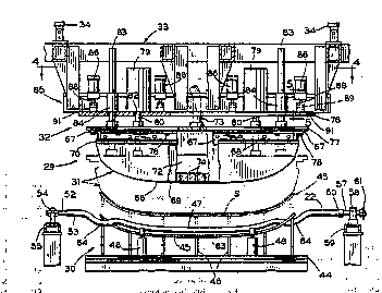
With reference now to Fig. 2. there is illustrated
the novel glass sheet bending apparatus of the invention
comprehensively designated ld, embodied in a conventional
horizontal press bending apparatus, identified generally
at 15. The apparatus lS more particularly includes a
continuous conveyor system 16 for supporting and conveying
glass sheets 8 along a generally horizontal path through a
heating furnace 17 for heating the sheets to their
softening point or bending temperature, a press bending
station 18 embodying the novel bending apparatus 1~
whereat the sheets are bent to the desired shape, and
thereafter to subsequent stations (not shown)..where the
heated bent sheets are appropriately cooled so as to be
tempered or annealed for subsequent:fabricating-steps.
The glass sheets 8 are conventionally heated in a
controlled manner while being carried sequentially through
the furnace 17 on aligned conveyor rolls 19 forming part
of the conveyor system 1~. The sheets,-heated to their
proper bending temperature,iexit:-the-furnace:through.an..
opening 20 in.the rear.end wall-21 and are-transferred.~
onto a second series of..conveyor rolls 22,-.also forming a
part of the conveyor system-16.-=The rolls 22-support and
. 30 convey~the glass sheets,.8 horiæontally into and-within the
bending station 18 before and after bending, and then~
W093/020~6 PCT/US92/05881
9 2~91:1~2
advance the bent sheets to the next processing step (not
shown) typically tempering or annealing of the sheets.
The press bending station 18 more particularly,
comprises a skeletal framework 25, generally in
rectangular parallelpiped form, including upstanding
corner posts 26 interconnected at their top and bottom by
longitudinal beams 27 and transverse beams 28 to form a
rigid box-like structure. The rolls 22 of the bending
station are drivingly mounted upon the framework in a
conventional manner (not shown). Mounted within the
framework 25 for reciprocating relative movement toward "`'
and away from each other are the upper and lower press
members 29 and 30 which are provided with opposed
complemental shaping surfaces conforming to the curvature
to which the sheets are to be bent.
The upper or male press member 29 comprises a
substantially solid shaping element 31 and is mounted upon
the novel support structure of the invention, generally ,
designated 32. The support structure 32, as will be
hereinafter more fully described, is in turn carried upon
a platen frame 33.~ The platen frame~is,prefera~ly, ,~ ....
constructed to be vertically adjustable in order.to.:
accommodate glass parts bent to varying degrees of
curvature between the opposed press members. Accordingly,
the platen frame 33 is operatively attached at each of its
corners within the framework 25 to the lower ends~of..screw
jack rods.3~ of associated screw jacks,35 carried.on,a
framework comprised by the beams 27 and 28 atop the -. .. .
framework 25. Also carried atop the.framework is a .......
motorized drive unit 36 adapted to drive.the screw jacks.
35 in unison for rètracting or extending the rods.3~ to .
W O 93/02016 PC~r/US92/OS881
('
correspondi~ ~lr~ ~ or lower the platen ~rame 33 and the
shaping element 31 carried thereby.
The lower or female press member 30 is mounted for
vertical reciprocal movement and is carried upon a platen
frame 3~ similar in construction to the platen frame 33.
In order to insure that the platen frames move freely up
and down along a precise vertical path within the
framework 25, they are provided at each of their corners
with stabilizing roller guide means 39. The guide means
39 include brackets 40 affixed to the corners of the
platen frames 33 and 38. Each bracket carries a plurality
of rollers ~1 suitably mounted to rollingly engage track
plates 42 affixed to adjacent angularly disposed faces of
the associated corner posts 26. The pla~en frames are
thus held firmly against lateral movement while being able
to move freely up and down along a vertical path.
The lower press member 30 is of conventional outline
or ring-type construction, and normally resides in a rest
position below the rolls 22 of the bending station '8.
The press member 30 is mountsd for vertical reciprocal
movement'to lift a''shèét 8 from the rolls 22 and press `it
against-the upper press member 29, and then return the
bent sheet to the rolls 22 for advancement out of the
.
bending station 18 for further processing.
More particularly, as shown in Figs. 2 and 3, the
lower press member 30 comprises a base member ~ secured
.. . ' ;. ... . . . .~ . . . ,. . ~ . . . . . . . . . .
to the platen frame 38'and'a shaping rail 45 affixed in
spaced relation to the base member by'méans of a series of
~ ,.. . . .... .-- , . .. .,. .~ . . .. .. . .
mounting posts ~6. 'The''shaping rail'conforms in outline
to the glass sheets to be bent, and is'provided on its
uppér face"with an upwardly directed shaping'surfacè 47 ~to
impart the desired curvature to the sheet. The particular
,
~ , : : . ' : - . ': ~
WO93/02016 PCT/US92/05881
1 6 ~
11
outline of the shaping rail ~5, as well as the specific
curvature of the shaping surface 47, of course, are
dictated by the predetermined finished shape of the glass
sheet being bent and can vary as desired. ,A spaced pair
of vertically reciprocal stop means 48 is conventionally
provided on the base member 4~ between adjacent ones of
the rolls 22 for precisely positioning incoming glass
sheets 8 relative to the upper and lower press members 29
and 30, respectively.
The base member ~4 is carried by the lower platen
frame 3a and is movable therewith. A fluid actuated
cylinder So is mounted beneath the platen frame 38 and
carried by the beams 27. The cylinder includes a piston
rod 51 affixed at its distal end to the platen frame 38
for reciprocally moving the lower or female press member
30 between its retracted position, whereat the shaping
rail ~5 is below the conveyor rolls 22, and its raised
position whereat the shaping rail lifts a heated sheet 8
from the conveyor rolls and presses it against the male
press member 29 between the.complementary.shaping.surfaces
of the male element 31 and the:shaping,rail ~5,-:.to bend it
to a predetermined curvature.--Upon-completion of bending,
the piston rod'51 is retracted.to lower.the platen frame
38, thereby retracting the shaping:rail 45 beneath the `:
conveyor rolls 22 .and depositing the bent sheet,thereon.;.:-
for advancement out'of..the,bending.station.~
~ The conveyors..rolls 22.employed.in the,bending.area-
are.preferably of .the contoured type comprising~:an inner
--hollow, stationary core-member~.and an-outer, flexible;,c~,
load carrying sleeve rotatable thereabout;' Such contoured
conveyor rolls~arei.disclosed.and-described-~in U.S. Patent
No.-'.~j905;794.which~is.:incorporatedi.herein by reference.--
.
W O 93/02016 ~ O ~ 1 1 6 .~ PC~r/US92/05881
12
The construction of the roll per se does not constitute
part of the present invention, and reference may be had to
the patent for details of the construction of a preferred
form of core member and rotatable sleeve.
Contoured rolls of increasing curvature may be
employed leading'into the press bending area to preform
the glass sheets prior to bending between the opposed
shaping s~rfaces. Likewise, such contoured rolls may be
advantageously employed in conveying the bent sheets from
the press bending apparatus into an adjacent processing
station.
As best shown in Fig. 3, the contoured conveyor rolls
22 include a core member 52 as of stainless steel tubing
and an outer, flexible, load carrying sleeve 53
surrounding and freely rotatable about the inner core
member.. At one end of the contoured rolls the stationary
core member 52 extends beyond the end of the ro~atable
sleeve 53 and is secured aga~nst rotation by suitable
mounting means 54 upon a side rail 55 of the structural
framework.. At its other or driving end, the core member
52 telescopingly receives a stub-shaft--(not shown) which
is fixed to .the core member and concentrically journalled
within a rotatable collar-57. ,The collar.57 is journalled
for rotation in a bearing 58 carried.on a,:side rail 59 of
the structural.framework..:.The.end of,the outer sleeve 53 .
is attached to,;the.rotatable collar 57,.by a.coupling ,.-
member 60,,,fixedly secured on the collar... A pinion 61,
adapted;to;be:.driven by,.a suitable endless drive.chain ..
(not.shown)'-, is.rigidly,secured,on the collar.~57. Driving
:of the pinion 61 by the drive chain thus,rotates the ,..,. ,-
collar 57.about,.the stationary stub shaft~affixed.to.the
core member 52-and,3~in:~.turn,~,.rotates the:.coupling member.
. ~ .
- . .................................. ..
-. . ::~,. . .. . -
~W 0 93/02016 PC~r~US92/05881 ~; ;
13 2~91.~2 1~
60 so as to cause the outer sleeve 53 to rotate about the
core member.
The series of rolls which are dlsposed in the press
area are configured so as to permit unhindered operation
S of the lower or female press member 30. To that end, the
rolls 22 include a generally concave central portion 63
which engages the lower surface of the sheet, and opposite
generally U-shaped end portions 64 which pass beneath the
lower shaping rail ~5 while in its lowered position.
The upper male press member 29 of the invention is of
the so-called solid or continuous type. To that end, the
male shaping element 31 includes a continuous glass
shaping surface identified qenerally at 66, having a
configuration c~mplementary to that of the lower female
press member 30. The shaping element 31 is formed of any
suitable refractory material capable of withstanding the
elevated temperatures to which it is subjected. Angle
brackets 67 affixed to the upper edge of the shaping
element 31 as by fasteners 68, are provided for mounting
the shaping element to the support structure 32 of the
invention, as wiil:'be'heréinafter more-fully~:described.
~ To provide a resilient non-abrasive surface for
contact-with the'heat'softened glass.sheet and to provide
insulation, the shaping'surface~66 is covered with,a sheet
69 of heat-resistant cloth,'such as-woven or knit
fibërglass or the like.'" The cloth ~heet-69-is.stretched
' tautly over thë shaping surface 66.and held.in place.by
any'suitabie méans such as the'`mounting brackets~70
'affixed as by'wêldin'g, to the lower end~of the angle
brackets 67.~
'' The^uppèr mold mëmb'er"is commonly adapted to provide
''positivë'and~negativë'-air~pressureato assist.in the ;:z
., ~ .. ~ ... . ~
: : :
'
WO93/02016 PCT/US92/05881
~'.?
20'~1~6'~ 14
shaping and handling of the glass sheets. The negative
air pressure, or vacuum, for example may be employed on
the shaping surface of the upper mold to assist in the
shaping of the glass sheet as the sheet is being pressed
between the opposed shaping surfaces. After bending, the
sheet is retained by vacuum against the upper shaping
surface as the lover mold member is retracted and a
carrier ring is brought into position to receive the sheet
and convey it out of the press area. The vacuum is
discontinued and a slight positive pressure is generally
initiated to release the sheet from the upper shaping
surface and deposit it on the carrier ring. .
To that end, the shaping element 31 is formed with a
chamber 72 that serves as a manifold for the positive and
negative air pressure. A conduit 73 is appropriately and
selectively connected to a source of air under pressure or
vacuum (not shown) and in communication with the chamber
72. The shaping element is provided'with suitable air
passages on the shaping surface 66 that communicate with
Z0 the chamber 72. The air passages may.be in the form of
drillëd~holes.~'such as at 74,:or the shaping element 31 may :
be formed of a suitable porous-refractory material that
:would permit a uniform flow~of-air along the shaping
:''sùrface without~the:need.for drilled~passageways.
In a conventional press bending apparatus, the,
shaping`elements of..the upper.-and.lower!pres members~are
mounted'on base'plates~that.:.-are carried by.~.the respective
upper:and lower platen.frames. The upp,er platen frame, as
heretofore described,..is provided with a r jack system which
permits vertical displacement of the platen frame and~
'-associated~press member.-:to properly position the upper
shapingrelement;relative.-~to~the.lower.shaping element as
- -
. .. , : :.
.
- :,
W093/02016 PCT/US92/OS881
` 15 2 ~
determined by the part to be produced. The elevation at
which the upper press member is positioned is determined
primarily by the curvature and thickness of the part.
This displacement system for adjusting the elevation of
the upper shaping element performs admirably and is
suitable for most present day requirements. However, the
trend toward aerodynamic styling has resulted in some
automobile windows having an exaggerated curvature which
is difficult if not impossible to produce efficiently on
the conventional bending apparatus.
In accordance to the present invention a novel
support structure 32 for carrying the upper shaping
element is provided which enhances the versatility of the
conventional press bending apparatus. The support
structure includes means that permit rapid and controlled
reciprocation of the upper press member into and out of
the pressing elevation in the bending cycle.
The novel support structure 32 comprises a base plate
76 adapted for attachment to the upper platen frame 33, in
a conventional manner as will be hereinafter more fully
described, and a subplate 77 for carrying the shaping --
element 31. The shaping element is secured to the
subplate by means of fasteners 78 through appropriate
apertures (not shown) provided in the angle brackets -67
and subplate 77.
The:subplate 77;is mounted for reciprocation on the
base plate 76. To;.that end, a plurality of linear
actuators, such as fluid cylinders 79, for-example, are
suitably mounted on the base plate 76 with the associated
piston rods 80 extending through appropriate openings 82
provided~-in the base-plate. The-piston~rods~are ~connected
at their free ends to the subplate 77.; -Guideposts~83, .
,
,
~' . .
W093/020l6 PCT~US92/05881
209~ ~ ~2
16
connected at their lower ends to the ~our corners of the
subplate 77, respectively, extend upwardly through
suitable bushings 8~ mounted on the base plate 76 for
sliding movement therethrough to properly guide the
subplate in its vertical reciprocating movement.
The base plate 7C is detachably secured to the platen
frame 33 in a conventional manner which permits easy
removal for maintenance and changeover from one part to
another. The platen frame 33 includes a mounting platform
85 having a plurality of actuating cylinders 86 attached
thereto that are adapted for supporting the base plate 76.
To that end, as best shown in Fig. 5, the free end of each
respective piston rod 88 is provided with an enlarged head
89 that is captured by the opposed upper walls 90 of an
associated C-shaped mounting bracket 91 affixed to the
base plate 76. Thus, as can be readily appreciated,
retracting the piston rods 88 with the heads 89 captured
by the associated brackets 91, will urge the base plate
upwardly into intimate engagement~with the platform 85
securely attaching the press member 29 to the platen frame
33. :Conversely,'the'''piston rods-88 are extended to ~
relieve the upward force exerted by the heads 89'against
the upper walls 90 of'the brackets 9i','3to permit :
disengagemént therefrom and-easy removal';of'the press -
member. -`
'-' In a typ'ical press~'bending'operation~ i the sheet is
heated'in''a furnace' to'*he bending~temperature and - ~-
théreafter''lcarried on~ho'rizontally 'aligned conveyor rolls
into position' for~bending;between the upper'and lower~
3~ press' me'mb'ers. The~`'l'ower press member is then raised to
'`liftlthè sheet~'off'th'e-'rolls and'into-pressing-engagement
with~the uppér'p'ress''member:bending'the sheet to the' -
~
.. .
. ~ .. .. .. ,' - .' ' ~ . . . .
~093/02016 PCT/US92/05881
17 ~911~2
desired curvature. The upper press member, generally, is
stationary as the sheet is lifted into engagement with its
shaping surface and at an elevation that does not
interfere with the sheet as it is conveyed into and out of
the press area. The elevation at which the upper press
member is set is primarily determined by the curvature and
thickness of the part being produced. The deeper the
curvature, the greater the distance the lower press member
must travel to lift the sheet off the conveyor rolls.
Since this travel is limited by the maximum stroke of the
cylinder employed and by structural obstructions that may
exist on the press member, it is not always possible when
bending deeply curved parts to set the stationary position
of the upper press member at an elevation high enough to
insure that it will not interfere with conveyance of the
glass sheet. As previously mentioned, while the
conventional jack system associated with the upper press
member can be employed to cycle the press member into and
out of position for pressing, it is relatively slow and
will have an adverse effect on the rate of production.
'Reviewing-'briefly operation,of the invention
hereinabove described, glass sheets ~ are carried through
the furnace 17 by the conveyor 16 where the temperature is
gradually raised to the softening polnt of the glass. The
heated sheets are received from the furnace upon contoured
rolls whereupon they-.tend to sag into.conformity with"the
rolls as they are advanced into position.for press,bending
bètween-theiupper.and-lower press members 29 and 30.
Prior to~the sheet entering the press area,.,the piston
rods 80 "of 'fluid actuators 79 ,are retracted to raise the
upper'press member~29;into the,elevate~d;rest,.position as
shown in solid lines in Fig.,3, to allow.for the
WO93/02016 ~ PCT/US92/05~1
18
unobstructed conveyance of the sheet into the press area.
Of course, at this time the lower press member 30 is in
the lowered position, with the shaping rail 45 below the
supporting sur~ace of the rolls.
When the leading edge of the sheet engages the stop
means ~8 the sheet is properly positioned, at which time a
suitable timing mechanism (not shown) is activated to
extend the piston rods 80 to lower the upper press member
31 into the press bending position shown in phantom in
Fig. 3. At the same time the cylinder 50 raises the lower
press member 30 to lift the sheet from the conveyor for
press bending between the shaping sur~aces ~7 and 66.
The elevation at which the sheet is press bent
between the shaping surfaces is determined by the stroke
of the lower cylinder S0 and is conveniently set to
substantially correspond to the maximum extension of the
piston rod 51. The upper press member 29 is then set to
this elevation by appropriate adjustment.of the screw
jacks 35 in a manner to properly position the shaping
surface at the bending elevation upon full extension of
the piston rods 80.' It will-be~appreciated that.the press
bending sequence bf operation can be varied without
departing from the'scope of the invention.: The upper . '
' press member 29 may be lowered to the-press bending
elevation and stationary when the lower press member 30 is.
raised to press'thë-sheet thereagainst. Converselyj-the
'' iower p'ress member may'be~raised to elevate the sheet.to
the' proper bending';position and stationary,as the.upper
press member is lowered to press bend-the sheet.~
'Likewise, the two-'press members may converge to - .
simultaneously m^ee~'''at-'-the-press bending elevation.to
press the sheet'therebetween.~'-.. . ,:.;.,. -,:,. ~ -,.
W O 93t02016 P(~r/US92/OS881
lg ~9~ 2
After the sheet ~ is precisely curved between the
shaping surfaces ~7 and 6~, the lower press member 30 is
retracted and the sheet is deposited on the contoured
rolls for advancement into a further processing station.
While the sheet has by this time generally cooled
sufficiently to retain its shape, the contoured rolls
provide support to assure that further sagging does not
occur upon immediate removal of the support of the shaping
rail ~5.
It will thus be apparent that the reciprocating
action provided by the novel support structure 32 of the
invention when utilized in conjunction with the screw jack
system of a conventional bending apparatus, is capable of
press bending glass sheets having various degrees of
curvature without adversely affecting the normal rate of
production. Moreover, in many instances the support
structure can be utilized to increase the production rate
when bending glass sheets having more shallow curvatures.
To that end, the elevation above the conveyor rolls at
which the sheet.is bent is reduced to the minimum distance
allowable to :adequately clear the-rolls instead of the
el~vation-as determined by the maximum,stroke of the lower
cylinder. Thus, the travel of the lower press member.is
reduced which ultimately results in a decrease in the .
press.cycle time.
Referring-now.to.:Fig.-,6-there:is shown a . . .... ..
com~unication satellite.,dish or parabolic reflector 93
produced in accordance~to.the present.,invention on a press
bending apparatus utilizing a.shuttle~carrier ring~for;.............. ~, -
transporting the curved sheet out of,.the bending area~ ~
after it is shaped to~the~,desired curvature. The .-.;,-,...
:~satellite dish..93-~is3bowel-shaped in the form of a ,-,;."
.
WO93/02016 PCT/US92/OS88!
20~ 20 ~ :.
paraboloid of revolution and includes a deeply curved or
displaced central portion 9~ and an upper circumferential
edge portion or rim 95. The central portion 9~ is .
provided with a plurality of suitable apertures 96 for
mounting the dish and attaching associated equipment
thereto.
The press members utilized to produce the satellite
dish 93 are similar in construction to the press members
utilized to produce the backlight lo and comprise a so-
called solid upper male press member 98 and a continuousring-type lower female press member 99. The upper and
lower press members 98 and 99 are provided with opposed
complemental shaping surfaces and are mounted for
reciprocating movement toward and away from each other
within the framework 25 on the respective upper and lower
platen frames 33 and 38. . .
The upper press member 98 is carried upon the novel .
support structure 32 of the invention and comprises a
substantially solid shaping element loO having a
continuous glass shaping surface 10' in the form of a .
paraboloid~of~revolution.'~' The 'shaping element-lOo.is ~.
formed of a suitable~refractory material with the shaping
surface 101 covered with a sheet 102-of heat-resistant :
cloth, such as woven or knitted fiberglass or the.like. A
chamber 103 is formed in the shaping element lOO and -
serves as a manifold:for:maintaining,positive--and.:negative
air pressure'supplied through the conduit 73.on-the.,..~
support-`structure 32,':as previously described.. Air... ;
passages-104 that communicate-with the chamber 103:~are?~
provided in the shaping surface 101.--Thus, a vacuum may ..,
be applied at-;the-shaping'surface 101 tor,assist in the .
shaping of the heat softened~glass.shéet:and thereafter~to
..
.,
- :
W O 93/02016 PC~r/US92/05881
21 2 09.1.~ ~ ~
support the curved sheet thereagainst as the lower press
member 99 is retracted. The curved glass sheet may be
returned to the conveyor rolls after the sheet has cooled
sufficiently to set its curvature or a shuttle carrier
ring, as will be hereinafter more fully described, may be
introduced to receive the curved sheet from the upper
press member and transport it into an adjacent processing
station.
The lower press member 99 comprises a base plate 106
that is secured to the platen frame 38 and a continuous
shaping rail 107 affixed in spaced relation to the base
plate by means of a series of mounting posts 108. The
shaping rail includes an upwardly directed shaping surface
109 complemental to the upper shaping surface lol of the
shaping element loo.'
The heat softened glass sheet is supported in a
generally horizontal plane on the conveyor rolls 22 as it
exits the furnace and is position~d for bending between
the opposed press members 98 and 99. To that end, at
least the rolls that extend through the lower press member
99 are of the contoured:type-'and-include a''horizontally~-
extending central-portion 111 and opposite-generally'U- -
shaped portions:112''`which pass beneath the lower shaping
rail-:107 while'in its~lowered position. - '' -'
i '''As.best-shown in Figs. 7 and-8, a'shuttle mechanism
indicated.generally at 113,-incIuding-a carrier-ring-114
and:a-carrier-ring transport apparatus~115, is'provided --
for transporting the/'curved-glass sheets'~from the bending
station 18-~to~`~an-unloading''station''117 whereat the":curved
sheet'is removed fr'om the':'c'arriér ring'''il4'and placed'on a
take-away roller'conveyor~'section-'118.~ Su'ch~:shuttle '-
mechanism~and~unloading~station-is -disclo'sed--and-described
.-:,, . ~ .
.
W093tO2016 PCTtUS92/OS881
2~ 22
in U.S. Patent No. 4,883,526, which is incorporated herein
by reference. The construction and operation of the same
per se does not constitute part of the present invention,
and reference may be had to the patent for details of the
construction and operation of a preferred form of the
shuttle mechanism and unloading station.
The carrier ring 114 is connected to a framework 119
which is carried by a pair of cantilevered longitudinally
extending support arms 120, affixed at their one end to
respective guide plates 122 (only one of which is shown).
The guide plates include bearings 123 which engage
horizontal rails 124 disposed on opposite sides of the
path of travel, thereby allowing horizontal movement of
the cantilevered support arms 120 and carrier ring 114 in
the direction of movement of the glass sheets through the
facility. A suitable drive unit (not-shown) is inter- , '
connected with the guide plates 122 for transporting the
carrier ring 11~ in a controlled reciprocating manner
between the bending and unloading stations 18 and 117.
- The unloading station 117 includes an elevator 126
located below the conveyor,rolls of the take-,away roll
section 118, and comprises cross supports 127, ,which,are
generally shaped to conform to the curvature of the bent
glass sheet. A suitable lift mechanism such,as a fluid
actuator 128, is provided to elevate the-cross supports
127 to lift the bent sheet from the carrier,-,ring ll~ when
the;,carrier ring,is properly positioned at the unloading
station. While the bent sheet is-in the elevated---- s -
~position, opposed support members~129 affixed,to,the,free-
end of the piston rod of respective actuating cylinders~130, are extended to occupy positions below~the
undersurface of the glass sheet.- As the cross~members 127
. . . . .
W093/02nl6 PCT/US92/OS881
~`` 209~1~2
23
are lowered the bent sheet is deposited on the extended
support members 129 as shown in phantom lines in Fig. 7,
and the carrier ring 11~ is shifted to a rest position
outside of the unloading station. Once the carrier ring
is clear of the supported sheet, the cross members 127 are
elevated to lift the glass sheet from the support members
129 at which time the support members are retracted and
the cross members 127 lowered to deposit the sheet on the
take-away roll section 118 whereupon it is advanced to the
next processing station.
Reviewing briefly operation of the invention, the
heated glass sheets B are advanced upon the conveyor rolls
22 into position for press bending between the upper and
lower press members 98 and 99. When properly positioned,
the sheet is lifted from the conveyor rolls 22 by the
shaping rail 107 to a stationary pressing location above
the rolls 22 at which time the fluid actuators 79 are
activated to lower the shaping element lOo from its rest
position into engagement with the glass sheet for press
bending between the shaping surfaces 101 and 109. A
vacuum-is;initiated on-the shaping~surface lOl to support
the curved sheet thereagainst as the shaping element loo
is raised to a holding position at an elevation to allow
entry of the carrier ring 11~. At the same time the
shaping rail 107 is retracted to its rest position below
the conveyor rolls 22. The carrier ring 114 is moved into
position beneath the shaping element 100 and the shaping
element is lowered to position the curved sheet 8
approximate the support surface of the carrier ring 114,
as indicated in phantom lines in Fig. 8. The vacuum on
the shaping surface 101 is abortad, depositing the sheet
onto the carrier ring 11~. The shaping element 100 then
.
WO93/02016 2 ~ 24 PCT/US92/05881
is retracted to the upper rest position and the carrier
ring 11~ and the supported curved sheet are transported to
the unloading station 117 whereat the sheet is transferred
to the take-away roll section 118 as heretofore described.
W~ile the aforementioned sequence of operation
describes the upper shaping element 100 as being lowered
into pressing engagement with glass sheet on the
stationary lower shaping rail 107, it is anticipated that
the upper shaping element lO0 can, as well, be lowered to
the press bending elevation and held stationary as the
lower shaping rail 107 is raised to lift the sheet from
rolls for press bending between the shaping surfaces lO1
and lO9. It also is anticipated that the upper shaping
element 100 and lower shaping rail 107 may arrive
simultaneously at the press bending elevation for press
bending the sheet.
It is to be understood that the forms of the
invention herewith shown and described are to be taken as
illustrative embodiments of the same, and that various
changes in the shape, size and arrangement of parts, as
well as Yarious procedural changes, may~be~resorted to
without departing from the spirit of the invention.
..... ... . . . . . .
, , ,,J, ! , _ , .. _,,, _ , , : . . ... . ... .
30 ~ r ~ ^-
'