Note: Descriptions are shown in the official language in which they were submitted.
~ 2091279
1 FIELD OF THE INVENTION
2 This invention relates to a method for constructing a
3 gas chromatogram from sequential ion mobility spectra
4 generated by gas chromatography with ion mobility detection
(GC/IMD).
6 sAcKGRouND TO THE INVENTION
7 An ion mobility detector (a.k.a. ion mobility
8 spectrometer IMS) chemically ionizes the effluent material
9 from a gas chromatographic unit and separates the product
1~ ions on the basis of their mobilities through an atmospheric
11 pressure gas under the influence of an electric field. By
12 gating the ion current in the drift region in
13 synchronization with a multi-channel detector, the ion
14 current can be scanned as a function of drift time,
producing an ion mobility spectrum (IMS). One IMS may be
16 acquired every 50 ms. It is therefore feasible to ac~uire a
17 series of IMS's during the course of a chromatographic
18 separation and construct a chromatogram (i.e., a plot of
19 instrument response versus retention time) from such a data
set.
21 Previous methods for processing GC/IMD data involved
22 integration of the IMD response over a portion of drift time
23 domain. Selectivity was achieved by choosing the
24 integration window to include analyte peaks and exclude
interferant peaks, when possible. A nonselective mode was
26 achieved by choosing the integration window to include only
27 the reactant ions, and monitoring the depletion of the
28 integral.
29 There are certain problems inherent in GC/IMD that peak
integration does not address:
31 a. An operator is required to select the boundaries of
32 integration windows, even for the non-selective mode. This
33 consumes time and introduces operator subjectivity into the
34 data analysis.
b. IMS lineshapes are often ill-suited to simple
36 integration: the peaks may be purely resolved, there may be
.
.
- ~91279
I multiple peaks due to fragmentation or complexation (see
2 Figure 3). The line shape associated with an analyte can
3 vary significantly as a function of concentration.
4 c. Solvent impurities and column bleed can interfere very
significantly with analyte signals.
6 d. Limited linear dynamic range.
7 SUMMARY OF THE INVENTION
8 In the present invention the two-dimensional nature of
9 a GC/IMD data set is recognized. Each IMS represents a
sampling of the contents of the ion reactor over the
11 duration that the electrostatic gate is open (typically 200
12 us). This is instantaneous on the time scale of
13 chromatographic peak evolution, and therefore each IMS may
1J be considered to be a "snapshot" of the GC eluate at a given
retention time. It was found to be useful to regard the
16 retention and drift time domains to be orthogonal, and to
17 treat the processing of a GC/IMD data set as a two-
18 dimensional problem.
19 The species responsible for the chemical ionization,
the reactant ions, are continuously present in the apparatus
21 as a result of ionization of a portion of the drift gas by a
22 radioactive source. The reactant ions are visible as a peak
23 or cluster of peaks in an IMS (see Figure l). When a
24 product elutes additional peaks appear in the IMS (see
Figures 2 and 3). Simultaneously, the reactant ion peaks
26 shrink as the reactant ions are depleted by the chemical
27 ionization process. The depletion results in saturation at
28 high analyte concentration, which limits the linear dynamic
29 range of GC/IMD with respect to analyte concentration.
The present invention provides a method for the
31 conversion of a time series of ion mobility spectra signals,
32 output from an ion mobility detector configured as a GC
33 detector into a chromatogram. It also provides a method
3~ that is capable of generating a time series of ion mobility
spectra encoded in the digital data format described herein,
.: .
.: : :, : : , ~
3 2091279
1 to facilitate the execution of method steps for providing a
2 gas chromatogram.
3 The preferred embodiment of the present invention
4 employs a vector space model (defined by the mathematical
equations herein) of the GC/IMD data set that defines
6 instrument response in terms of vector magnitudes in this
7 space. The present invention requires no assumptions
8 regarding the line shapes of ion mobility spectra, requires
9 no interpretation of lineshapes by an operator, in
particular the selection of integration boundaries, and is
11 capable of quantifying complex ion mobility spectra signals
12 for storage, further processing and/or display. This
13 function may be performed without operator involvement. The
14 invention can accept a set of ion mobility spectra from the
operator that can be used to construct a mathematical basis,
16 that can then be used to exclude the spectral information in
17 these spectra from the chromatographic reconstruction, for
18 the purpose of removing interfering signals from the
19 chromatogram. This function may be performed with minimal
operator sophistication or involvement.
21 The invention can independently and concurrently
22 monitor signal responses due to reactant and production
23 currents, and can combine these two quantities by use of a
24 response function for the purpose of enhancing the linear
dynamic range of the instrument response. All of the above-
26 noted functions can be performed in real time, or from data
27 stored on a storage means such as a hard disk.
28 In accordance with an embodiment of this invention, a
29 method of producing a gas chromatogram is comprised of
obtaining a time series of ion mobility spectra from the
31 output of an ion mobility detector configured as a gas
32 chromatography detector and converting the time series into
33 signals for display.
.. . .. - . ~ . . . . -
~ .
:
2091279
I BRIEF INTRODUCTION TO THE DRAWINGS
2 A description of embodiments of the invention will now
3 be described in detail below, with reference to the
4 following drawings, in which:
Figure l is a graph illustrating an analyte-free ion
6 mobility spectrum,
7 Figure 2 is a graph illustrating an ion mobility
8 spectrum containing reactant ions and an impurity,
9 Figure 3 is a graph illustrating an i.on mobility
spectrum similar to Figure 2, but at a later time,
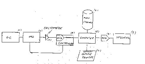
11 Figure 4 is a block diagram of apparatus which may be
12 used to carry out the method of the invention,
13 Figure 5A illustrates a data set used in the process of
14 the invention,
Figure 5B illustrates the structure of a data record of
16 the data set in figure 5A,
17 Figure 6 is a flow chart illustrating process steps of
1~ the invention,
19 Figure 7 is a graph illustrating a gas chromatogram
resulting from the invention in its non-selective mode,
21 using the same data as in Figures l, 2 and 3, and
22 Figure 8 is a graph illustrating a gas chromatogram
23 resulting from the invention in its selective mode, using
24 the same data as in Figures l, 2 and 3.
DETAILED DESCRIPTION OF THE INVENTION
26 This invention utilizes a particular data processing
27 algorithm, which is preferably embodied in a configuration
28 of hardware and software. The preferred hardware
29 configuration ls shown as a block diagram in Figure 4. A
3(~ gas chromatograph l is interfaced to an ion mobility
31 detector 2 by a suitable interface such as a heated transfer
32 line. The ion current is detected and amplified by an
33 electrometer 3. Digitizer/controller 4 converts the
34 electrometer output to digital format, controls the IMD
voltages and gate timing, and transmits a time series of
36 IMS's to a digital computer 5. The computer 5 should
. . : : : , : : ~ : ::: -
: :: : : . . : .
: . : ~ . : .
~ . , :
2l~91279
r \ )
1 contain a CPU of sufficient power to translate the signals,
2 in accordance with the process steps shown in the equations
3 described below, in the time intervals between successive
4 IMS's (typically 50 ms). In practice, a computer based upon
an Intel 80386 microprocessor has been found to be adequate
6 for this purpose. The computer should have access to a mass
7 storage device 6 such as a hard disk drive for storage and
8 retrieval of the method step processor sequence files,
9 chromatographic data files and GC/IMD data files. The
computer should have input and output devices 7 such as a
11 keyboard for operator input and a CRT. Finally, a digital
12 to analog converter 8 and an external integrator 9 may
13 optionally be included.
14 The controller hardware should be capable of collecting
the raw analog data, digitize it, and supply it to the
16 computer in a preferred format, shown in Figure 5. Each
17 GC/IMD data set 20 is an ordered series of records 22, each
18 consisting of a time stamp 24, proportional to the retention
19 time at which the current IMS was acquired, and an array of
n data points 26 representing the IMD response versus ion
21 drift time. An entire chromatographic run generates a data
22 set comprised of p records of preacquisition data and N+l
23 records of chromatographic data. The preacquisition data
2q represent the most recent set of p records prior to
commencement of the chromatographic run. The purpose of the
26 preacquisition data is to provide the processing algorithm
27 with a sample of data containing no signal due to eluent,
28 i.e., unperturbed reactant ion spectra. The function of
29 continuously updating a buffer containing this data may be
performed by the digitizer.
31 During the course of a chromatographic run the data is
32 sent from the digitizer to the computer for processing.
33 There should be software resident in the computer capable of
34 executing the calculations required by the data processing
algorithm, described below. The data may be processed as it
36 is acquired (real-time processing), displayed and/or printed
.. .;
209127~
I if desired, or the data set may optionally be stored in a
2 file and processed later. The same file may be reprocessed
3 a number of times in order to optimize the processing
4 parameters. Two processing modes are possible: non-
selective mode, which requires no operator input, and
6 selective mode, which requires operator input.
7 Non-selective mode processing produces a response in
8 the chromatogram whenever an IMS is encountered that is not
9 directly proportional to the reactant spectrum, derived from
1~ the preacquisition data. The resulting chromatogram
contains peaks for all eluents, regardless of the nature of
2 the associated IMS lineshapes. Non-selective mode
13 processing requires no operator input regardless of the
14 sample type or the instrument status. It is useful to
configure the software so that non-selective mode is the
16 assumed default, i. e., non-selective mode will be used
17 unless the operator instructs otherwise. It should be noted
18 that because non-selective mode requires no operator input,
19 it could be readily adapted to an application such as
automated process monitoring.
21 Often chromatograms, particularly those produced by
22 GC/IMD, contain signals due to impurities and column bleed,
23 which may overlap and obscure the desired analyte signals.
24 The selective mode, by making use of the information in the
drift time domain, allows undesired peaks to be removed from
26 a reconstruction. The selective mode requires the operator
27 to review a previously processed chromatogram and select
28 retention times corresponding to the maxima of signals to be
29 excluded from the reconstruction. The operator need not
consult the original IMS~s. The list of retention times and
31 the associated spectral information are stored in a method
32 file. The process of reviewing a chromatogram and
33 generating a method file may be facilitated by a graphical
34 interface to the software. If a set of interferants appear
reproducibly in all chromatograms produced by a particular
, , ~:
.
7 209127~
analytical method, the same method file may be used for all
2 processing.
3 Spectral features arising from reactant and product
4 ions are discernible in the drift time domain. The data
processing algorithm described herein allows the signal
6 levels due to reactant and product ions to be monitored,
7 efficiently, independently and concurrently. Although these
8 two quantities may be of interest in their own right, in
9 accordance with an embodiment of this invention they can
1() also be mathematically combined in a response function that
11 has a greater linear dynamic range than either individual
12 quantity because the function compensates for the depletion
13 phenomenon described above. It should be noted that this
14 approach to response linearization has not been previously
employed in ion mobility spectrometry.
16 The result of processing in either mode is an array of
17 N+l data points each proportional to the chromatographic
18 response at the corresponding retention time. This data
19 array in all respects resembles, and may be treated as, a
conventional gas chromatogram.
21 The components of this array may be passed in real time
22 for further processing. For example, the data stream may be
23 reconverted to an analog signal for input to an external
24 integrator. Alternatively, the chromatographic data may be
written to a file and further processed at a later time.
26 The original GC/IMD data set, which may be voluminous, need
27 not be stored, unless future reprocessing is anticipated.
28 This method uses an algorithm related to the so-called
29 Gram-Schmidt reconstruction algorithm used to process
GC/FTIR data sets, but with some important differences. The
31 following definitions are used in the description of the
32 algorithm below.
33 The data set is regarded as a set of n-dimensional
34 vectors. The data set has two parts: a set of preacquistion
vectors ~ and a set of
36 postacquisition vectors ~
,
8 2091279
I The instrument response at a given retention time is
2 defined to be the magnitude of the corresponding vector:
3 1 ~ I a i ~
6 A subset of the data vectors ~qt3 (t=O,~.. ,m) is chosen
7 consisting of those vectors containing spectral information
8 to be excluded from the reconstruction. The zeroth member
9 of the set q~O represents the analyte-free reactant ion
spectrum and is defined by
~ (2)
12 ~2 ~
13 where the summation notation indicates that the vectors are
14 summed component-wise. The other members of~ qt~ may be
chosen arbitrarily from ~Vt~ . These vectors are specified
16 in the method file.
17 The analyte-free instrument response is a scalar nR~
18 defined by
n R~ ¦ y / ~ J ~r ~
2() (3)
21
22 This quantity may be used as a reference value in order to
23 calculate the depletion of the reactant ion signal at any
24 point in the data set. The reactant ion response at time t
is a scalar nRt defined by
26
27 n ~ - J ~ . v~ (4)
28
29 This quantity may be used directly as a non-selective, non-
linearized instrument response. However, it is advantageous
3I to use a linearized instrument response, see Eq. (9) below.
32 An orthonormal basis ~ui~ is constructed from ~qn~ by
33 use of Gram-Schmidt orthogonalization
34
., . . . , :
.,. - .: -,: ~ ~ : ~ :
9 209127~
,1 Yo
2 1% 1 (5)
~JA q" ~ qV ) ~, ( 6)
(,~ ( 7 )
7 The set of unit vectors ~u~i~ defines a hyperplane in
8 the vector space. This hyperplane contains all possible
~ linear combinations of the undesired vectors~q~n~ . For any
vector ~V ~ we may take the component orthogonal to the
11 hyperplane defined by ~u~i~ to obtain a vector linearly
12 independent of ~q~n~ The spectral information in ~qn~ is
13 effectively filtered from this vector. The filtering
14 process is effective even if the desired and undesired
signals overlap in the retention time domain. Therefore,
16 the product ion response at time t is a scalar npt given
187 by n ~ c ' ~ ) 4, (8)
19
The scalars nRO/ TRt and npt contain sufficient
21 information to calculate the magnitude of product ion
22 production and reactant ion depletion at time t. These
23 scalars may be combined in a response function, based upon a
24 mathematical model of the physical processes occurring in
the ion mobility detector, that will have a superior dynamic
26 range with respect to analyte concentration. In this
27 embodiment of the invention two response functions (R and Rs
28 defined below) are utilized based UpOII a simple kinetic
29 model of the ionization process. The linearized, non-
selective instrument response function at time t, to be used
31 in1 conjunction with the non-selective mode processing, is
32 given by
34
I() 2091279
,
1 The linearized, selective instrument respon6e function at
2 time t,to be used in conjunction with the selective mode
3 proces6ing, is given by p
S jaS(~)2 ~ (n~ o
6 The computer should be programmed to perform the
7 calculations specified by equations (l) to (lO) in a certain
8 sequence, given by the flowchart depicted in Figure 6.
g Referring to the numbered elements of Figure 6, the
1() data (l) are read in real time from the A/D converter (or
11 alternatively from a disc file). The quantity nr is
12 calculated by use of equation (3). The operator may choose
13 selective mode processing (3), otherwise non-selective mode
14 is automatically executed. In the latter case the
quantities nRt (4) and R (5) are calculated by use of
16 equations (4) and (9), respectively, for each of the N+l
17 data records. The N+l values of R are passed to output
18 (ll).
19 If at step (3) selective mode has been chosen, the
operator must supply a method file (6) that specifies the
21 vectors ~qt3 The basis set ~ui} is constructed by means of
22 Gram-Schmidt orthogonalization (7), using equations (5), (6)
23 and (7). The quantities nRt (8), nPt (9) and Rs (lO) are
24 calculated by use of equations (4), (8) and tlO),
respectively, for each of the N+l data records. The N+l
26 values of Rs are passed to the output (ll). The data stream
27 entering the output device is the chromatographic data.
28 Note that in Figure 6, the output (ll) destination can be
29 disk storage or further processing, as chosen by the
3() operator.
31 Figure 7 shows a gas chromatogram produced by non-
32 selective mode processing of a GC/IMD data set. Figure 8
33 shows a gas chromatogram produced by selective mode
34 processing of the same GC/IMD data set. In Figure 8 a large
solvent peak at l.0 minutes and an interferant peak at 2.0
Il 2~91279
1 minutes have been edited out, while the analyte peak at 2.4
2 has not been affected.
3 The invention has been described above as applied to
4 the processing of GC/IMD data. The invention can be applied
to any chromatographic method, for example high performance
6 liquid chromatography (HPLC) or supercritical fluid
7 chromatography (SFC), employing ion mobility detection.
8 Furthermore, the invention can be applied to any
9 chromatographic detection system that combines chemical
1~ ionization with a means of resolving and detecting reactant
11 and product ions, for example, chemical ionization mass
12 spectrometry (CIMS). The advantages of the present
13 invention described herein are valid in these other cases.
14 A person understanding this invention may now apply it
to other designs. All are considered to be within the scope
16 of the present invention as defined in the claims appended
17 hereto.
18