Language selection

Search

Patent 2091283 Summary

Third-party information liability

Some of the information on this Web page has been provided by external sources. The Government of Canada is not responsible for the accuracy, reliability or currency of the information supplied by external sources. Users wishing to rely upon this information should consult directly with the source of the information. Content provided by external sources is not subject to official languages, privacy and accessibility requirements.

Claims and Abstract availability

Any discrepancies in the text and image of the Claims and Abstract are due to differing posting times. Text of the Claims and Abstract are posted:

  • At the time the application is open to public inspection;
  • At the time of issue of the patent (grant).
(12) Patent: (11) CA 2091283
(54) English Title: FUME HOOD WITH PANEL RETENTION SYSTEM
(54) French Title: HOTTE AVEC PANNEAU-SUPPORT
Status: Expired and beyond the Period of Reversal
Bibliographic Data
(51) International Patent Classification (IPC):
  • B08B 15/02 (2006.01)
(72) Inventors :
  • BECK, MARSHALL K. (United States of America)
  • BASTIAN, JOHN M. (United States of America)
(73) Owners :
  • HAMILTON INDUSTRIES, INC.
(71) Applicants :
  • HAMILTON INDUSTRIES, INC. (United States of America)
(74) Agent: BORDEN LADNER GERVAIS LLP
(74) Associate agent:
(45) Issued: 1999-08-03
(22) Filed Date: 1993-03-09
(41) Open to Public Inspection: 1994-03-19
Examination requested: 1996-08-12
Availability of licence: N/A
Dedicated to the Public: N/A
(25) Language of filing: English

Patent Cooperation Treaty (PCT): No

(30) Application Priority Data:
Application No. Country/Territory Date
947,775 (United States of America) 1992-09-18

Abstracts

English Abstract


A fume hood includes a housing with wall panels
disposed in side-by-side relation and a top member disposed
substantially perpendicularly to the wall panels. Connecting
blocks which engage edge portions of adjacent panels connect
these adjacent panels together. Clip members defining recesses
for receiving edge portions of wall panels or of the top member
secure the wall panels to the top member.


Claims

Note: Claims are shown in the official language in which they were submitted.

CLAIMS
1. A fume hood comprising: a housing having an interior chamber with a front
opening which allows access to the chamber, said housing including: a base member; a
plurality of wall panels disposed substantially perpendicularly to the base member; a ceiling
panel disposed substantially perpendicularly to the wall panels; said wall panels extending
between the base member and the ceiling panel; first connecting means for securing the
ceiling panel to a wall panel, said first connecting means including clip means with a
resilient portion which defines a recess for receiving an edge portion of one of either said
wall panel or the ceiling panel and first securing means for securing the clip means to the
other one of the ceiling panel or said wall panel, said clip means receiving an edge portion
of only one of either said wall panel or the ceiling panel; and second connecting means for
connecting adjacent wall panels together, said second connecting means including block
members for engaging adjacent edge portions of adjacent panels and second securing means
for securing the block members to the adjacent edge portions.
2. A fume hood comprising: a housing having an interior chamber with a front
opening which allows access to the chamber, said housing including: a base member; a
plurality of wall panels disposed substantially perpendicularly to the base member; a ceiling
panel disposed substantially perpendicularly to the wall panels; said wall panels extending
between the base member and the ceiling panel; first connecting means for securing the
ceiling panel to a wall panel, said first connecting means including clip means defining a
recess for receiving an edge portion of one of either said wall panel or the ceiling panel and
first securing means for securing the clip means to the other one of the ceiling panel or said
wall panel; second connecting means for connecting adjacent wall panels together, said
second connecting means including block members for engaging adjacent edge portions of
adjacent panels and second securing means for securing the block members to the adjacent
edge portions.
3. The fume hood of claim 2, wherein the block members engage inside surfaces

of adjacent edge portions of adjacent wall panels.
4. The fume hood of claim 2, wherein the first and second securing means for theblock and clip members includes screws.
5. The fume hood of claim 2, wherein adjacent wall panels lie perpendicularly toone another.
6. The fume hood of claim 2, further comprising a base member disposed
substantially perpendicularly to the wall panels at an opposite end of the wall panels, said
base member being secured to the wall panels by the first connecting means.
7. The fume hood of claim 2, wherein the clip means includes a two piece clip
member with a resilient portion defining the recess and a rigid portion releasably secured to
the resilient portion, the securing means securing the rigid portion.

Description

Note: Descriptions are shown in the official language in which they were submitted.


20912~3
FUME HOOD WITH PANEL R~l~NllON SYST~
BACKGROUND OF THE lNv~lIoN
Field Of The Invention
The present invention relate3 to a fume hood with a
panel retention system, and more particularly to a fume hood
with a retention system which allow~ quick and easy assembly of
the various panels o~ the fume hood hou~ing.
De~cription Of The Prior Art -
Fume hood~ typically include c~ g for bringing
utilities such as gas, ~e~sed air, water and electricity to
their working space. These com~oner.ts must be ~cce~sible for
initial con~ection at the time of installation, inspection by
code authorities for various municipalitie3, and maint~ e and
repair. G~1ning ~ccess to these component~ o~ fume hoods is
geneLally a dif~icult and ti~a conauming ~ nre.
The prior art includes a variety o~ ~ume hood~ with
complicated housing~ comprising close toler_ _g comyunen~C which
requir- accur~t~ and ~e ~ive fabrication p~o~e~ 3 a~ well as
complicat-d and tim~ con~ming assembly ~cesY~. Some of
these ~ume hood~ hav~ g~tly ACQese dooro built into exterior

20912~3
panels to allow inspection of the various utility components
disposed in the fume hood.
The fume hood of the present invention provides a
simple housing structure with fastener~ and connectors which
allow quick and easy assembly and ~is~csembly of the housing
structure. It minimizes the number of fasteners used to secure
the various panels of the housing together; and it provides a
corrosion resistant enclosure. The fume hood of this invention
is a simple construction which minimizes the expense o~
manu~acture and assembly.
SU~2ARY OF TH~ INVt~ r-.10~
In accordance with one embodiment o~ this invention, a
fume hood includes a housing definins a cha~ber with a front
access op~n~n~. Th~ housing includes a plurality o~ wall panels
~jspo~e~ in side-by-side relation. ~ ceiling panel lies
substantially perpendicularly to the wall pAnel~ at one end of
the pAnel~.
Clip means co~e~-~ the ceiling panel to the wall
panels. Each Or these clip mean~ define~ a ~~ce~s for receiving
one o~ the wall and ceiling pAnel~. ~crews or other securing
~ean~ fixedly secur- the clip means to tha other o~ the wall and
ceiling pal~9t~.
CG.~.e~ing blocks secura adjacent wall panels
together. Each block ~ , le~ an edge portion of one panel and
an edg- portion of an ad~acent panel, and securing devices such

20912~3
as screws secure the block to these edge portions.
BRIEF DESCRIPTION OF T~ DRAWINGS
For a more complete underst~ g of the present
invention, one should now refer ts the emho~i -nt illustrated in
greater detail in the acc~ nyinq drawings and described below
as an example of the invention. In the drawings:
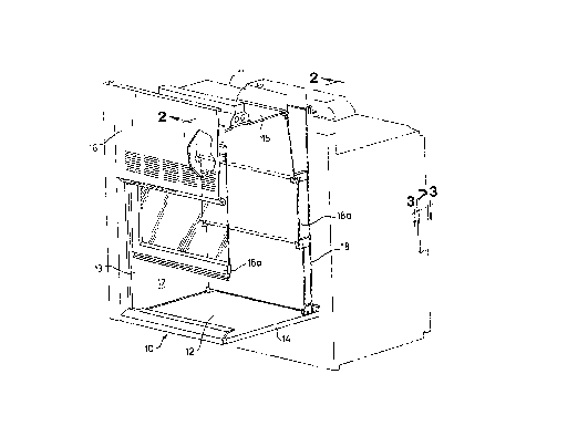
FIG. 1 is a perspective view of thQ fume hood of the
present invention with a portion of the fume hood cut away;
FIG. 2 is a sectional view taken along line 2-2 in FIG.
1; and
FIG. 2A is an enlarged view o~ detail A in FIG. 2.
FIG. 3 i3 a sectional view taken along lina 3-3 in FIG.
1.
While the following describes thQ invention in
COImG~iOn with one embodiment, one ~hould understand that the
invention is not limited to this embodlment. Furthermore, one
should understand that the drawings are not to scale and that
graphic ~ymbol9, diagrammatic ~e~L~ase.tation~, and fragmentary
views may, in par~, illustrate the embod~ment. In certain
in~tA~-s~,-the dis¢losurQ may not include dQtails which are not
nece~C-ry ~or the underst~nAing o~ the p~ invention.
nFT~TTFn ~FC~KI~,lON OF TR~ n~wT~Gs
In the illu~tration qiven and with re~a~en e to FIG. 1,
the num-ral 10 designates the fume hood Or th~ t
- 3 -
., ,.. . ~ .

2~12~3
invention. This fume hood generally includes a housing 11 and a
blower (not shown). The housing defines a chamber 12 with a
front opening 13 and comprises a base 14, a ceiling panel 15, a
front panel 16, side panels 17, a rear pan~l 18, and a baffle
assembly 18a. A sash 16a, slidably mounted to the housing 11
opens and closes the opening 13.
The panels and other members identified above are
members made out of metal, hard plastic, or any other material
of sufficient strength, rigidity and corrosion resistance. The
pAn~l~ which define the ch~ ~-r 12 and the baffle plates are
made of cement board or a poly~ster material. Alternatively,
they may be polyvinyl chloride, poly~rv~ylene, or any other
suitable material. They, as well as tha fastenerR described
below, resist the chemical action o~ fumes in the chamber 12.
Clip member~ 19 and 20 secura the front, side and rear
panels to the ceiling panel 15. The clip member 19 secures the
ceiling panel 15 to the ~ront panel 16: and the clip members 20
secure the ceiling panel 15 to the rear p~nels 18 and the side
panels 17. The clip member 19 i3 a resilient thermoplastic
material (e.a., polyvinyl chloride) formed to de~ine a recess 21
which receives an edge portion of tho ceiling panel 15. Screws
22 or si~ilar securing means secure the clip me~ber 19 to the
~ront pan~l 16 bet ~~~ the ~ront panol and rigid (e.g.,
metallic) strip 23.
Each clip member 20 is a two piece ~tru~LuL_~ a
clipplng portion 20a made of the same material as th~ clip
- 4 -
:
' ' ' ' ' '' " ' ' ' ' , '' : .' ' ,. ' : ' ' , ' '.' ' . ' , ' '

20~12~
member 19 and a rigid portion 2Ob made of metal such as steel or
any other rigid material of high strength. Each one includes a
recess 24 which receives an edge portion of a wall panel (panel
18 in FIG.2). Screws 25 or similar securing devices fixedly
secure the portions 20b of the clip members 20 to the ceiling
p~nel 15 or the base 14.
The cross-sectional configuration of each reces~ 21 and
24 is trapezoidal with the entrance to the recess having a
smaller width than ths width at ths bottom of the recess. The
width of the entrance to the reces3 i9 also smaller than the
thickness of the wall panel which the recess receives ~o that
the clip may engage the panel in a press-fit. This feature also
allows the use of panels with different thic~nsa~i.
810c~ members 26 are nade o~ hard pla~tic (e.g.,
polye~ter), metal, or any other material o~ high ~LLeII~th~
rigidity, and co~osion re~istanc~ and secur~ ad~acent wall
panels together. The block 26 shown in FIG.3 cQn~ects a side
panel 17 with the rear panel 18. It e~-Jn~e~ both the panel 17
and tAe panel 18. A screw 27 se~uLe~ an edge portion o~ the
panel 17 to the portion of the block 26 which ~'u~ n~ the panal
17; and a ~cr~w 28 ~ecure~ an edg~ portion of the panel i8 to
the portion of the block 26 which ~r,~ ths pan~l 18. An
angle strip 29 which extend~ fro~ the bottom of the base 14 to
the ceiling pan~l 15 serves as a co~l.e~ treatment at the
c~ Lion baL~ea.~ the panels 17 and 18. Suitable cel~ne~-ing
device~ such a~ nut~ and bolts ~e_ul~ this strip 29 to the
- 5 -

20912~3
L-shaped portions 20b of the clip members 20.
While the applicant has shown one embodiment of the
present invention, one will understand, of course, that the
invention is not limited to this embodiment, as those skilled in
the art to which the invention pertain~ may make modifications
and other embo~; -nts of the principles of the invention,
particularly upon considering the foregoing te~hings. The
applicant, therefore, by the ~pp~n~9~ claim~, intends to cover
any modifications and other embodiment which incorporate those
features which constitute the essential features of this
invention.
What is claimed is:
-- 6 --
.. ..

Representative Drawing
A single figure which represents the drawing illustrating the invention.
Administrative Status

2024-08-01:As part of the Next Generation Patents (NGP) transition, the Canadian Patents Database (CPD) now contains a more detailed Event History, which replicates the Event Log of our new back-office solution.

Please note that "Inactive:" events refers to events no longer in use in our new back-office solution.

For a clearer understanding of the status of the application/patent presented on this page, the site Disclaimer , as well as the definitions for Patent , Event History , Maintenance Fee  and Payment History  should be consulted.

Event History

Description Date
Inactive: Reversal of expired status 2013-10-09
Time Limit for Reversal Expired 2013-03-11
Letter Sent 2012-03-09
Grant by Issuance 1999-08-03
Inactive: Cover page published 1999-08-02
Inactive: Final fee received 1999-04-22
Pre-grant 1999-04-22
Letter Sent 1998-10-29
Notice of Allowance is Issued 1998-10-29
Inactive: Status info is complete as of Log entry date 1998-10-22
Inactive: Application prosecuted on TS as of Log entry date 1998-10-22
Inactive: Approved for allowance (AFA) 1998-09-30
Request for Examination Requirements Determined Compliant 1996-08-12
All Requirements for Examination Determined Compliant 1996-08-12
Application Published (Open to Public Inspection) 1994-03-19

Abandonment History

There is no abandonment history.

Maintenance Fee

The last payment was received on 1999-01-28

Note : If the full payment has not been received on or before the date indicated, a further fee may be required which may be one of the following

  • the reinstatement fee;
  • the late payment fee; or
  • additional fee to reverse deemed expiry.

Patent fees are adjusted on the 1st of January every year. The amounts above are the current amounts if received by December 31 of the current year.
Please refer to the CIPO Patent Fees web page to see all current fee amounts.

Fee History

Fee Type Anniversary Year Due Date Paid Date
MF (application, 5th anniv.) - standard 05 1998-03-09 1998-02-09
MF (application, 6th anniv.) - standard 06 1999-03-09 1999-01-28
Final fee - standard 1999-04-22
MF (patent, 7th anniv.) - standard 2000-03-09 2000-02-02
MF (patent, 8th anniv.) - standard 2001-03-09 2001-02-20
MF (patent, 9th anniv.) - standard 2002-03-11 2002-02-18
MF (patent, 10th anniv.) - standard 2003-03-10 2003-01-29
MF (patent, 11th anniv.) - standard 2004-03-09 2004-02-11
MF (patent, 12th anniv.) - standard 2005-03-09 2005-03-09
MF (patent, 13th anniv.) - standard 2006-03-09 2006-02-07
MF (patent, 14th anniv.) - standard 2007-03-09 2007-02-08
MF (patent, 15th anniv.) - standard 2008-03-10 2008-02-08
MF (patent, 16th anniv.) - standard 2009-03-09 2009-02-12
MF (patent, 17th anniv.) - standard 2010-03-09 2010-02-18
MF (patent, 18th anniv.) - standard 2011-03-09 2011-02-17
Owners on Record

Note: Records showing the ownership history in alphabetical order.

Current Owners on Record
HAMILTON INDUSTRIES, INC.
Past Owners on Record
JOHN M. BASTIAN
MARSHALL K. BECK
Past Owners that do not appear in the "Owners on Record" listing will appear in other documentation within the application.
Documents

To view selected files, please enter reCAPTCHA code :


To view images, click a link in the Document Description column. To download the documents, select one or more checkboxes in the first column and then click the "Download Selected in PDF format (Zip Archive)" or the "Download Selected as Single PDF" button.

List of published and non-published patent-specific documents on the CPD .

If you have any difficulty accessing content, you can call the Client Service Centre at 1-866-997-1936 or send them an e-mail at CIPO Client Service Centre.


Document
Description 
Date
(yyyy-mm-dd) 
Number of pages   Size of Image (KB) 
Abstract 1994-06-03 1 28
Drawings 1994-06-03 1 42
Claims 1994-06-03 2 89
Description 1994-06-03 6 271
Claims 1998-08-25 2 72
Representative drawing 1999-07-26 1 16
Representative drawing 1998-08-12 1 24
Commissioner's Notice - Application Found Allowable 1998-10-28 1 163
Maintenance Fee Notice 2012-04-19 1 172
Correspondence 1999-04-21 1 28
Fees 2005-03-08 1 36
Fees 1997-02-13 1 71
Fees 1996-01-17 1 48
Fees 1995-01-23 1 64
Prosecution correspondence 1996-08-11 1 28
Courtesy - Office Letter 1996-09-24 1 50
Prosecution correspondence 1998-05-27 3 101
Examiner Requisition 1998-02-23 2 65
Prosecution correspondence 1996-11-25 1 30