Note: Descriptions are shown in the official language in which they were submitted.
WO9~/04145 PCT/EP~1/01668
20914~6
.. , 1 Ij
~YEi~E~ OF ~aC~ ING D~VI~
.. The invention relates.to a system of machining
devices particularly for machining so~called lead frames,
such as punching, cutting and bending. Such lead frames are
intended~for carr,ying chips. The.intended processes to be
5 performed on the lead.frames are.performed in a so called
cutting and bending machine. Such a cutting and bending
: machine needs to combine great accuracy with the highest
possible machining speed. For machining the lead frames are
carried by neans of transporting-means through the machine, .
10 placed on a machining station and subjected to a machining,
whereafter the transporting means pick up the lead frames
'again and transport them to a following station. The entire
process takes place automatically. - . .
: '' In older machines the machine tool is driven via
15 pneumatic means in order to perform an active stroke. A
pneumatic cylinder coupled to the tool carrier is employed
for this purpose. Later.machlnes we:re driven via hydraulic
meansisince.the.forces:generated ~h~erewith;are greater than
thè forces-obtained~.via:pneumatic mleans..;A complication in
20-suchi a type of de~ice is that a comparatively large stroke
len~th is required since the transporting':means require a
--free-passag~ in order,to.be~able to place the lead frame on ,,
a~imachining station and~then pick it up.again.,It..is
urthermorei-desirable~to,be-.~able~to..~isually~l~sipect the
25'' ma'chining -~ zone- ~f ~ ;t~ _iSi~ jJ'" '" j Z'-r'~", ,,- , ,,, ";, ,,, ~
The hydraulic driving:.also.has;other:,different.
rawbacks.:~Firstly;~r-.the~tusei;ofsa~hydraulic,,medium is not
.easily compatible.with~theiclean enYironment:in:which,ithe
-3-~ ~process ~must~take~place.. 'In~addition,~he.-accuracy~,of`~jthe .~:
30 movement;~ia~hydraulic',-means-..'is~limited; since this movement ,
is only guided by one guide, the hydraulic piston:,rod,.~In
the past different steps,have,~been taken to increase this
accuracy, but the pos'sibilities are'limited. Should it be
:
1, :" ' -
PCT/EP91/01668
Encl. to my letter of July 22, 1992
'~.
'`i .
desired to further.increase the speed, the hydraulic drive :~ imposes limits, since the.speed is limited among other
reasons because the driving hydraulic medium has to surmount
~a dead point during a complete cycle of the active stroke.
:~5 The result is that the transport of the lead frame can only
be pex~ormed when it has been established that the stroke of
. the tool has ended at a predetermined position.
The invention has furth~r for its object to obviate ;~
the abov~ mentioned drawbacks. Partic~lar objectiv2s here ~ :
.. ' 10 must be a grea-t stroke length, a high speed, a clean
1 operating environment and great accuracy of the movement of
the tool relati~e to the lead frame.
From JP-A-6165461 a cutting device as defined in the
preamble of claim 1 is known.
Besides cutting the leads of a lead frame other
operations should be machined, such as bending and punching.
Thereto, according to the prior art, the lead frame should
be taken ~ut from such a machine and it should be placed in
another machining device.
It is the object of the i~vention to provide an
integrated system in which all the necessary operations are
being carried out automatically in a controlled way.
-. This is..achieved with the features as de~ined in
claim 1.
: 25 By providing an integrated modular automatically
operatin~ system a economically suitable way of performing
operations is obtainedO
The modular construction ~urnishes great advantages,
particularly in production. The machining d~vices can be
30 separately produced and tested. They Gan then be assembled
~ into a desired system. This provides a great deyree of
: flexibility.
!Su~TlTUTE SHE~T
WO 92/04145 2 0 9 1 4 4 ~ PCT/EP91/0l668
The member driving the tool carrier is preferably
formed by an ecGentric rotatably driven by a motor and
situated in the main frame of the machining device.
A continuous movement is obtained by this method of
5 driving, which allows a higher machining speed. Such a drive
method is'possible since the forces to be exerted for the
machining are limited.
Coupled to the eccentric and connected to the tool
carrier is an auxiliary frame, which is vertically guided in
lQ the main frame for performing relative to the main frame an
'a-ctive'stroke performed between two end positions.
The end positions of the auxiliary frame are
ad~ustable relative to the main frame. The option is
therefore available of having the active stroke performed
15 relative to the machining surface at a position where this
is deemed desirable. The stroke depth can hiereby be
regulated. In addition, with a view to inspection, the
working'surface can be made entirely visually a-ccessible as
desired.
The setting of the iend positions of the auxiliary
frame preferably takes place by means of a shaft rotatable
in the'main frame and driven by a st~epping motor, which.
shaft is coupled to the auxiliary frame~over a.screw,: ;,
':con~nèction.'By using a stepping motor and.a very fine screw
25'thrèad connection a very accurate adjustment.of:the-end-
positi'ons'~o~ ~he'auxiliary-frame~can be obtained. ---
~ 'r'The-shaft~is preferably a-keyway shaft and:is-
; received for`vertical movement.:in a belt-pulley:driven
~~r'otatab'ly'-b'y~'the'stepping-motor..~ Y ~-r r 1.~
- ~ For-~;synchronously controlling~.the.machining devices
and~th'é~'operation-lof theJtransp'ort-means the control-device
"'is' c`oupl'ed~tb sensors which'~detect thev~angle position of the
eccentr"ic in~''each''of-the'~'machining devices.-.The\system:o~
machining'~'devices--~is"li~ontrolled'ion the.tbasis of'the
35 information obtained under the.control~:of.Jsoftware:~in-the.~.
microprocessor incorporated in the"control~,device.
' '~ ~ ,,., ~ :
WO92/04145 PCT/EP91/U1668
~ A4'6 4
The transport means for horizontal and vertical
transport in the machining device are driven by a cam disc
placed on the main shaft.
For driving of the transport means for horizontal
5 transport the ridge disc is coupled over a fork-shaped
member, which performs a linear movement when.the cam disc
rotates, to a pinion and a toothed rack, wherein the toothed
rack, by means of a lever eccentrically connected to the
toothed rack, provides a reciprocating movement of the
lO transport means slidable along guide tracks.
For driving of the vertical transport ~he main shaft
is coupled to cam discs disposed in parallel which drive
operating members moving guide tracks for horizontal
transport of a lead frame between end positions in vertical
15 direction.
: To avoid damage the system preferably contains a
sensor connected to a release mechanism for a coupling
; , between the drive motor and the main shaft for detecting an
overload in the drive of the tool~ :
In order to ensure that after decoupling the device
.comes rapidly to a standstill, a brake coupled to the
eccentric is energized at release of the coupling when an
overload-is detected.-~ ,,L,,:,,,f; ? i.i "; ., ~
.-.-... For the..transport between the machining devices the
25 transport means.-.consist of-an endless belt with~a feed end
for receiving.a.,lead fxame passed on by the horizontal,
transport means of.a preceding machining de~ice and a
'discharge.end.for,.transferring a lead.frame to the, . ;.
horizontal transport means:of;a-~following;machining~device,
30-:a stop~for~:'a.~lead::,frame placed abovesthe,,endless belt,
.wherein-the material of~the-,endless belt-has a friction .
..; coefficient such.-,that,:..when,.thellead.frame strikes against
:the stop,:the belt~slips,.relative to the,lead,frame. ,,~
m.':.;The invention will,.be.,:fu~therielucidated-with , .
35 reference~.to~the~drawings~ r
In the'.drawings~ ,-,O~0, st ~0~ i3~
Fig. l shows a schematic perspective view of a
; system according to the invention,
~.` :,
.. . , .. .::.: . .,.:,,, : .
WO92/04145 ~ PCT/EP91/016~8
"~ 5 : -
Fig. 2 shows a perspective cut away view according
to the line II-II in fig. l,
Fig. 3 is a sectional view ~long the line III-III
from fig. 2;
. Fig. 4 shows a similar view to fig. 3, but in
:~ another of the end positions of the auxiliary frame, and
Fig. 5 shows a detail V from fig. 4.
Fig. 6 ~hows a perspective view o~ the horizontal
driv~ and vertical drive o~ the transport means.-
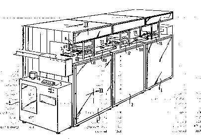
:The system according to the invention comprise~
machininy devices 1, 2, 3 accommodated in cabinet-like units
l, 2, 3, the operation of which devices is controlled and
mutually synchroniæed~from the control module 4. A
microprocessor is incorporated in the control module 4. The
15 control module 4 has a control panel 5 and a control unit in
the form o~ a monitor 6.
: The lead frame 7 for machining is transported by
means of a transport means 8 which is movable over
. lengthwise guides 68 and 69 in a machining device. At the
20 location of each machining device l, 2, 3 is a machining
station ll, 12, 13 respectively, where the various required
processes, including punching, bending, cutting and the
~; like, can be performed.-~Each.~achinting device,comprises;at
~ least a main frame l4~and an~auxiliary frame 15 that is
25 movable vertically relative to the main frame l4 with guide
:;rods 40,-.-4l, 42j~43 in bearings l6, l7. The main frame
comprises,-transverse bearers 44,A45 which are connected at a
~distance by.:vertical~walls.146; 47. The bearings l6, l?,are
arranged in-the transverse,bearerst44-~and 45:respectively.
30~ s~ The"auxiliary~.. frame.l5 comprises a horizontally~
running,..lower,coupling,member 49~connected~to,the guide
rods~0,~;4l,u,~2,~43 and,t~arranged at.i;aivertical;distance,
therefrom, an upper,~coupling-,member 49,that is likewise~
fixedly,~connected to the~uide~rods~40, 4l,~"42,~43~..The~tool
35 consists o~.a~.tool,carrier,~l83bearing~,aJtool l9 and a work.
~surface.38~co-acting~herewith. Coupled;to~the-~upper. A~
coupling member ~3.iof the~auxiliary frame~15tis.a tool-;.;
carrier 18 in which a desired tool l9 i5 placed. A shaft 20
... . . .
.: . . :
.
W092/04145 2 U 9 ~ 6 PCT/EP91/01668 t!
(
which carries an eccentric 21 is received rotatably in
protruding parts 50, 51, 5~ on the transvers2 bearer 44 of
the main frame 14. The shaft 20 is driven from the motor 22
via a transmission 23 and a belt pulley 24. The eccentric 21
S is mounted in bearings 25, 26 of the protruding parts 50 and
51 respectively. The eccentric carriers a spherical pivot 27
resting in an adapted bearing socket 28. With a rotation of
the shaft 20 the eccentric, and there~ore the auxiliary
: frame 15, moves between two and positions, one of which is
10 drawn in fig. 3 and the other in fig. 4. These end positions
respectively correspond to the open position of the machine
tool lg and the closed position thereof.
During the movement between,both end positions a
part 29 of the auxiliary frame 15 moves with thP shaft 30
15 coupled thereto in a bearing 31 in the transverse bearer of
the main frame. The coupling between the part of the shaft
30 and the auxiliary frame 15, in any case the flange shaped
portion 32 thereof, runs via a screw thread connection 33
(fig. 5). Using the stepping motor 34 the belt pulley 36 can
20 be rotated via the drive belt 35. Because the shaft 37 has a
keyway 37 which co-acts with corresponding ribs on the
inside of the bearing 31, the,shaft :30 rotates with the belt
pulley 36 therein carrying with it the part Z9. Due to,this
rotation movement the part 32 of the auxiliary frame and the
25 part 33 move in a lengthwise direction relative-to one
another so:that the auxiliarv'frame 15 undergoes a vertical
' movement. Indicated with broken lines in fig. 5:-is the~
':position of the auxiliary frame relative to the part 29 in
':'the~situation-iaccording'to fig.~-3 and'4.'In the present:
: 30 embodiment a~ according-to fig. 5-the--auxiliary.~rame 15 is
moved in-upward:direction so that thel:work surface 38 is
completely~accessible.'s-A subsequent'active' stroke'of the
eccentric 21 and therefore the auxiliary frame 15 will thus
'produce a higher lying~end-position of the-machine tool lg
35::than in'the posikion indicated'in fig.l3'and 4.~In-the, ';`
manne'r'outlined in:the'~oregoing, the depth of''the:active
stroke can-thèrefore be accurately controlled. ~ -
. . ... .. : ~1. ~: :.
W092/04145 91~ ~ 6 PCT/EP91/Ot668
Fig. 6 shows the manner of transport into a machi-
ning device.
Placed on th~ main shaft 20 is a cam disc 60 which
co-acts with a fork-shaped member 61 such that with a
5 rotation movement of the cam disc 60 the fork-shaped member
performs a linear reciprocating movement according to the
arrows shown. The fork-shaped member 61 carries with it
during the linear movement a pinion 63 which engages on a
worm gear 64 which is coupled to a shaft 65. Due to the
10 reciprocating movement of the worm wheel 63 the worm gear 64
rotates, as does the shaft 65 therefore which is mounted in
the frame. A lever 66 is eccentrically coupled to the shaft
65. At a rotation movement of the shaft 65, the lever
per~orms a reciprocating movement between two end positions.
15 The lever is coupled at the end with drive mean~ 67 which
move the transport means reciprocally along the guide track
69. -
There is therefore a one-way coupling between the
movement of the horizontal transport means and the rotation
20 of the main shaft 20 so that complete synchronization with
the movement of the tool of the-machining device is ensured.
As can be seen, there is also a one-way coupling
between the vertical transport of the lead frame in-the
machining device and the rotation of the main sha~t 20. The
25 main shaft 20 is coupled to the cam discs 73, 74 by an
endless drive belt 70 which is train~d over belt pulleys 71,
72. When the main shaft 20 rotates, the cam discs 73, 74 are
driven. The cam discs 73, 74 rotating synchronously and in
phase impart to the drive members 75, 76 a vertical movement
30 between two end positions. The members 75, 76 are coupled to
the respective guide tracks 68, 63 so that these likewise
undergo a vertical movement.
Because both the horiæontal and the vertical
transport is derived from the main shaft 2~ a complete
35 synchronization between the mutual movements and the
movement of the tool is ensured.
A releasing mechanism i5 arrangPd in the coupling
100 between the shaft of the driving belt pulley 24 and the
:
, " . . . .. . ... . ~, . .... ..
:,: , ,: . .: . . , :. .:
WO92/04145 PCT/EP91/01668
~14~G 8 ~
main shaft 20. The coupling is connected via means (not
drawn) to an overload sensor which measures the load of the
drive of the tool. In the case of overloading as a result l ;~
~ for example of incorrect placing of a lead frame, the
; 5 release mechanism of the coupling lQ0, controlled by a
signal ~rom th~ sensor, is set into operation and therefore
releases the shaft 20 from the drive shaft. A brake (not
shown) of for instance pneumatic type also comes into
operation which brings the main shaft and therefore the
lO eccentric to a standstill within a very short period of
time.
Finally, it is noted that for transport between the
machining clevices use is made of a buffer transporter llO. ~;
Such a buffer transporter llO consist~ of an endless belt
15 conveyor and a stop lll. During operation a lead frame is
placed on the endless belt conveyor llO by the horizontal
transport means of a preceding machining device. The lead
frame moves over the belt conveyor llO until it meets the
stop lll. After the lsad frame has c:ome to a standstill
20 against the stop, the belt slips uncler the lead frame. The
horizontal transport means of a following machining device
~ake the lead frame at a suitable moment in time from the
belt conveyor llO and carry;it~to the machining location on
the following machining device. ,-
- ,, . .: ., : ~ ,; , , , -
,. ~ . *****
-- . . ......... . . .
::~ , ~ , : : :