Language selection

Search

Patent 2091471 Summary

Third-party information liability

Some of the information on this Web page has been provided by external sources. The Government of Canada is not responsible for the accuracy, reliability or currency of the information supplied by external sources. Users wishing to rely upon this information should consult directly with the source of the information. Content provided by external sources is not subject to official languages, privacy and accessibility requirements.

Claims and Abstract availability

Any discrepancies in the text and image of the Claims and Abstract are due to differing posting times. Text of the Claims and Abstract are posted:

  • At the time the application is open to public inspection;
  • At the time of issue of the patent (grant).
(12) Patent Application: (11) CA 2091471
(54) English Title: APPARATUS FOR FILLING SACKS HAVING ONE OPEN SIDE
(54) French Title: DISPOSITIF DE REMPLISSAGE DE SACS AYANT UN COTE OUVERT
Status: Deemed Abandoned and Beyond the Period of Reinstatement - Pending Response to Notice of Disregarded Communication
Bibliographic Data
(51) International Patent Classification (IPC):
  • B65B 43/30 (2006.01)
  • B65B 3/28 (2006.01)
  • B65B 43/46 (2006.01)
  • B65B 43/54 (2006.01)
(72) Inventors :
  • HUWELMANN, HELMUT (Germany)
(73) Owners :
  • WINDMOLLER & HOLSCHER
(71) Applicants :
  • WINDMOLLER & HOLSCHER (Germany)
(74) Agent: AVENTUM IP LAW LLP
(74) Associate agent:
(45) Issued:
(22) Filed Date: 1993-03-22
(41) Open to Public Inspection: 1993-09-24
Examination requested: 1999-06-21
Availability of licence: N/A
Dedicated to the Public: N/A
(25) Language of filing: English

Patent Cooperation Treaty (PCT): No

(30) Application Priority Data:
Application No. Country/Territory Date
G 92 03 879.4 (Germany) 1992-03-23
G 92 07 679.3 (Germany) 1992-06-05

Abstracts

English Abstract


1090-30
APPARATUS FOR FILLING SACKS HAVING ONE OPEN SIDE
ABSTRACT
Sacks which are open on one side and are
preferably provided with side folds are gripped at their
side sections in the area of their open edges by pairs of
grippers, which can be displaced towards and away from each
other. The lateral walls of the sacks are pulled apart
adjacent the open edges between the grippers by suction
elements arranged in a rack of the apparatus. In the rack
there are arranged filling necks which can be lowered and
raised into and out of the open sacks. A sealing device
closes the open edges of the sacks which are closed by
moving apart the grippers thus pulling the edges tightly
against each other. In order to be able to detect the
desired net weight of the filling quantity with a high
accuracy, the pair of grippers and the drive means for the
opening and closing movements, and for the displacement of
the grippers towards and away from each other, are arranged
on carrying means which are connected with the rack by means
of weighing devices. This separate carrying means minimizes
the amount of the apparatus which must be included in the
gross weighing thereby minimizing the relative error.


Claims

Note: Claims are shown in the official language in which they were submitted.

1090-30
The embodiments of the invention in which an exclusive
property or privilege is claimed are defined as follows:
1. An apparatus for filling sacks open on one edge
having opposite lateral walls comprising:
a rack;
a filling neck which can be raised and lowered
supported by a rack;
a pair of cooperating grippers and associated drive
means for opening and closing the grippers and for
displacing the grippers towards and away from each other;
means for spreading apart the lateral walls of the sack
arranged on the rack;
carrying means for supporting the pair of grippers and
the associated drive means; and
weighing devices for operatively connecting the
carrying means including the pair of grippers, and the
associated drive means, to the rack.
2. An apparatus as claimed in Claim 1 further
including a sealing unit for sealing the open edge of the
sack.
3. An apparatus as claimed in Claim 1 wherein the
means for spreading apart the lateral walls of the sack
comprise suction elements.
4. An apparatus as claimed in Claim 1 wherein the
weighing devices comprise pressure measuring means.
5. An apparatus as claimed in Claim 1 wherein the
drive means includes:
two parallel guide rods hingedly connected to the
carrying means and the grippers forming a four bar system;
and
piston-cylinder units.
- 8 -

6. An apparatus as claimed in Claim 1 wherein pivotal
means are provided for preventing the filling neck from
contacting the sack which are moveable from a V-shaped
closed position to spread apart open position.
7. An apparatus as claimed in Claim 6 wherein the
pivotal means are hopper outlet doors.
8. An apparatus as claimed in Claim 7 wherein the
hopper outlet doors are mounted on the carrying means.
9. An apparatus as claimed in Claim 6 wherein the
pivotal means are stretcher plates.
10. An apparatus as claimed in Claim 9 wherein the
stretcher plates are mounted on the carrying means.
- 9 -

Description

Note: Descriptions are shown in the official language in which they were submitted.


1090-30
APPARATUS FOR FILLING S~CKS HAVING ONE OPEN SIDE
The invention refers to an apparatus for filling
sacks which are open on one side and which are preferably
provided with side folds.
During filling of the sacks it is necessary to
provide a certain filling weight in order to obtain units
with a uniform weight which can be sold by the piece.
In an apparatus which is disclosed in EP~A-290
879, sacks are filled via a filling neck with a
predetermined quantity of filling material which has been
previously weighed out, so that weighing during filling is
not necessary. This method is, however, impossible when
the sacks are filled with rnaterial having poor flowing
behaviour. For example, a liquid filling material of a high
viscosity tends to adhere to the filling neck or to the
guide means used for the filling, so that when a net filling
amount is fed through the filling neck, it is not clear
whether the complete quantity of filling material will be
received by the sack or bag.
If the filling of the sacks or bags with a
previously weighed net filling quantity is impossible, a so-
called gross weighing must be carried out, which means that
the sacks are weighed during filling and the sacks are
filled until the desired weight is reached. But this kind
of gross weighing is subject to the problem that not only
the sack, together with the filling amount, is weighed but
that also the means holding the sack during filling must be
weighed. The weight of the means holding the sack enters
into the gross weighing as dead weight, with the result
that, when taking into account the dead weight, even for
small relative errors (inaccuracies) in the gross weighing,
relatively large deviations from the desired net weight may
be obtained.
. .

From DE-PS ~9 716 as well as Erom US-PS 2 5~6 193
filling apparatus for sacks performing a gross weighing of
the filling quantity are known. In these devices, however,
in addition to the holding means for-the sacks to be filled,
the entire filling hopper arrangement is entered into the
dead weight weighed -therewith. For this reason it is
impossible in these known apparatus to keep the inevitable
relative measuring error small enough during weighing that
the absolute errors of the desired filling amoun-t can be
kept in the desired small, and therefore, negligible range.
Therefore, -the present invention seeks to provide
an apparatus for gross weighing of sacks during their
filling, with which the desired net weights of the filling
quantities can be obtained with a high degree of accuracy.
This problem is solved, according to the invention
for a filling apparatus of the kind mentioned above, by the
fact that the pair of grippers and the drive means for their
opening and closing movements and for displacing the
grippers towards and away from each other are arranged on
carrying means which are connected to the rack via weighing
devices. Hence, in the apparatus according to the
invention, only the means for holding the sack are suspended
from a weighing device or supported thereon, keeping the
dead weight as small as possible. Consequently, in the
apparatus according to the invention even with respect to
the net filling amount, the relative weighing error can be
kept small and the sacks or bags can be filled with the
desired quantity, even for filling materials with poor flow
behaviour or with high viscosity. In the apparatus
according to the invention the filling neck advantageously
is provided with a closing means at its lower section so
that the filling process can be interrupted when the desired
weight is reached, or when, taking into account the last
runnings of the filling quantity, -the desired nominal weight
has ~ust been reached.
-- 3 --
.

il 7 ~
After filling, the sacks illed by the apparatus
according to the invention can be sealed in the usual
manner. When the filled sacks or bags are made of a plastic
film of thermoplastic material, a transverse weld can be
used to seal the open edges which have been laid against
each other by displacing the grippers away -from each other.
Sealing can also be carried out by folding over the edges of
the opening and sealing them with transverse sewing seams,
e.g. by application of a rider strip.
Accordingly, the present invention comprises a
rack; a filling neck, which can be raised and lowered,
supported by the rack; a pair of cooperating grippers and
associated drive means for opening and closing the grippers
and for displacing the grippers towards and away from each
other; means for spreading apart the lateral walls of the
sack arranged on the rack; carrying means for supporting the
pair of grippers and the associated drive means; and
weighing devices for operatively connecting the carrying
means including the pair of grippers, and the associate
drive means to the rack.
The invention further includes a sealing unit for
sealing the open edge of the sack.
Advantageously, the weighing device consists of a
pressure measuring means on which the carrying device is
supported in the rack. There can be provided, for example,
two or three pressure pickups on which the carrying device,
consisting of a crossbeam or the like, is supported on the
rack.
The drive means moving the grippers of the pair of
grippers toward and away from each other may consist of two
~parallel guide rods hinged to the carrying device, which
form a four-bar system together with the grippers. The

four-bar system is pivotable by pressure-means piston
cylinder units, e.g. pneumatic cylinders.
For some filling material it may be necessary to
provide hopper outlet doors or stretcher plates in addition
to the filling neck. According to a further working
embodiment of the invention it is, therefore, provided that
hopper outlet doors or stretcher plates which can be pivoted
about parallel axes are mounted on the carrying means
adjacent the filling neck. These doors or plates can be
spread apart or moved into a V-shaped closed position by
drive means. In their closed V-shaped position, these
hopper outlet doors lie above the open edge of the sack or
bag. After the suction elements which open the sack have
been removed from the sack walls, the two hopper outlet
doors pivot into an open position, thereby moving into the
sack. This forces the opening edges apart so that the
filling neck may be moved into the sack without coming into
contact with it. Stretcher plates can be used instead of
special hopper outlet doors.
Working embodiments of the invention will be
explained in detail with reference to the following
drawings.
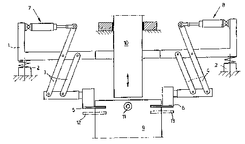
Figure 1 shows a lateral view of a gross weighing
device of a sack or bag filling apparatus with a feed
pipe in a schematic representation; and
Figure 2 shows a view of a gross weighing device, as
shown in Figure 1, in which addition hopper outlet
doors are provided.
.
In the apparatus according to Figure 1 the pair of
grippers 5 and 6 holding the sack during filling are mounted
on a carrying element or frame 1 which is supported on the
rack (not shown) of the filling apparatus by means of
pressure pickups or force pickups 2.
- 5 -
.
.
. ' ': ' ~: ' '
- ..

2~g:~7:~
Paralleloyram linkages 3 and ~ which are pivotally
connected to the frame, support at their lower ends a pair
of grippers 5 and 6 respectively. The pair grippers 5 and
6 holding and spreading a sack may be moved towards and away
from each other by means of piston cylinder units 7 and 8
connected to the parallelogram linkages 3 and ~ and mounted
on the frame 1. A sack 9 gripped by the pair of holding and
spread~ng grippers 5 and 6 is drawn open laterally in the
area of a filling hopper by suction elements 11.
Simultaneously, the pair of holding and spreading grippers
5 and 6 are moved towards each other. After opening the
sack 9 at the upper filling edge, the filling pipe 10 of the
hopper is lowered into the sack, whereupon the suction
elements 11 can be removed from the sack. A valve (not
shown) is associated with the filling pipe 10
advantageously, in the lower section thereof, which closes
the filling pipe 10 at the moment when the pressure pickup
2 indicates the predetermined weight for sack 9 and its
contents. Then the filling pipe 10 is lifted, and the pair
of holding and spreading grippers 5 and 6 are moved away
from each other in order to close the opening edge. At this
point a pair of transport grippers 12 and 13 are advanced
which grip the sack 9 and transport it away. An empty sack
is then transported into the area of the pair of holding and
spreading grippers 5 and 6 by an additional pair of
transport grippers (not shown).
The pair of holding and spreading grippers 5 and
6 consist of tong-like opening and closing clamping bars
which can be pivoted about transverse axes lying
approximately in the pivoting place of the parallelogram
linkages 3, ~. The holding and spreading grippers 5 and 6,
and their drive means are of known structure and are
therefore not described in detail.
The working embodiment represented in Figure 2
differs from that of Figure 1 in that for ~illing the sacks,
' , ' '
..
~ '

a filling hopper 14 is used wi-th which are associated the
pivotal hopper outle-t doors 15. During opening of the sack
or bag 9 the hopper outlet doors 15 are pivoted into the
sack 9 and come to rest against the inner sack walls. The
two swivel shafts 16 of the hopper outlet doors 15 are
connected with the frame 1' by means of sheet metal holders
or holding lugs 17. The manner of the bearing of the two
hopper outlet doors 15, and the drive means for opening and
closing them are well known and are therefore, not explained
in detail here. Since the hopper outlet doors 15 are
mounted to the frame 1' their weight is additionally entered
into the total weight when a gross weighing is carried out.
But since this weight is not very large, its effect is small
on the relative measuring error during the gross weighing.
The arrangement of the hopper outlet doors 15 prevents the
filling hopper 14 from coming into contact with the lateral
walls of the sack 9' to be filled, so that indefinable
weighing inaccuracies are prevented.
:
, ,.,' , ' . :
: ' :

Representative Drawing
A single figure which represents the drawing illustrating the invention.
Administrative Status

2024-08-01:As part of the Next Generation Patents (NGP) transition, the Canadian Patents Database (CPD) now contains a more detailed Event History, which replicates the Event Log of our new back-office solution.

Please note that "Inactive:" events refers to events no longer in use in our new back-office solution.

For a clearer understanding of the status of the application/patent presented on this page, the site Disclaimer , as well as the definitions for Patent , Event History , Maintenance Fee  and Payment History  should be consulted.

Event History

Description Date
Inactive: Adhoc Request Documented 2018-06-06
Appointment of Agent Requirements Determined Compliant 2018-05-18
Revocation of Agent Requirements Determined Compliant 2018-05-18
Inactive: IPC from MCD 2006-03-11
Application Not Reinstated by Deadline 2003-03-24
Time Limit for Reversal Expired 2003-03-24
Deemed Abandoned - Conditions for Grant Determined Not Compliant 2002-07-09
Deemed Abandoned - Failure to Respond to Maintenance Fee Notice 2002-03-22
Notice of Allowance is Issued 2002-01-09
Letter Sent 2002-01-09
Inactive: Approved for allowance (AFA) 2001-12-27
Amendment Received - Voluntary Amendment 1999-10-21
Inactive: Application prosecuted on TS as of Log entry date 1999-07-06
Letter Sent 1999-07-06
Inactive: Status info is complete as of Log entry date 1999-07-06
All Requirements for Examination Determined Compliant 1999-06-21
Request for Examination Requirements Determined Compliant 1999-06-21
Application Published (Open to Public Inspection) 1993-09-24

Abandonment History

Abandonment Date Reason Reinstatement Date
2002-07-09
2002-03-22

Maintenance Fee

The last payment was received on 2001-02-22

Note : If the full payment has not been received on or before the date indicated, a further fee may be required which may be one of the following

  • the reinstatement fee;
  • the late payment fee; or
  • additional fee to reverse deemed expiry.

Please refer to the CIPO Patent Fees web page to see all current fee amounts.

Fee History

Fee Type Anniversary Year Due Date Paid Date
MF (application, 5th anniv.) - standard 05 1998-03-23 1998-02-17
MF (application, 6th anniv.) - standard 06 1999-03-22 1999-02-18
Request for examination - standard 1999-06-21
MF (application, 7th anniv.) - standard 07 2000-03-22 2000-02-23
MF (application, 8th anniv.) - standard 08 2001-03-22 2001-02-22
Owners on Record

Note: Records showing the ownership history in alphabetical order.

Current Owners on Record
WINDMOLLER & HOLSCHER
Past Owners on Record
HELMUT HUWELMANN
Past Owners that do not appear in the "Owners on Record" listing will appear in other documentation within the application.
Documents

To view selected files, please enter reCAPTCHA code :


To view images, click a link in the Document Description column. To download the documents, select one or more checkboxes in the first column and then click the "Download Selected in PDF format (Zip Archive)" or the "Download Selected as Single PDF" button.

List of published and non-published patent-specific documents on the CPD .

If you have any difficulty accessing content, you can call the Client Service Centre at 1-866-997-1936 or send them an e-mail at CIPO Client Service Centre.


Document
Description 
Date
(yyyy-mm-dd) 
Number of pages   Size of Image (KB) 
Representative drawing 1999-04-01 1 17
Representative drawing 2001-12-28 1 13
Drawings 1993-12-11 2 36
Abstract 1993-12-11 1 29
Claims 1993-12-11 2 47
Description 1993-12-11 6 233
Cover Page 1993-12-11 1 20
Acknowledgement of Request for Examination 1999-07-06 1 179
Commissioner's Notice - Application Found Allowable 2002-01-09 1 164
Courtesy - Abandonment Letter (Maintenance Fee) 2002-04-22 1 182
Courtesy - Abandonment Letter (NOA) 2002-09-17 1 170
Fees 2000-02-23 1 38
Fees 2001-02-22 1 36
Fees 1999-02-18 1 40
Fees 1998-02-17 1 39
Fees 1995-02-27 1 68
Fees 1997-03-03 1 47
Fees 1996-02-20 1 49