Note: Descriptions are shown in the official language in which they were submitted.
13DV-10563
BYPA8~ INJECTO~ VALVE FOR
5vA~IAB~s CYCL~ AIRC~AFT ENGINE8
BACRGROUND OF T~E INVENTION
Fiel~ of the In~entio~
The present invention relates in general to noi~e
reduction in a high speed civil transport aircraft engine
and relates in particular to a valve which allows high
pressure fan bypass air to mix with lower pressure flade air
during takeoff.
De3cription of Prior Develop~0~t~
Noise reduction in current high speed civil transport
aircraft engines is accomplished through a combination ~f
high-~lowing the engine, that is, operating the engine at
its maximum airflow capability, and throu~h the use of
mechanical noise suppressors. Prior noise suppre~sion
schemes for a mixed ~low turbofan or variable cycle engine
10, such as schematically illustrated in Figs. 1, 2 and 3,
involve ~itting a fixed area noise suppressor 12 in the
primary exhaust stream 14 and introducing low temperature
bypass air 16 into the center of the exhaust stream, thu6
creating a coannular exhaust nozzle system. Although ~ngine
lO o~ Figc. 1, 2 and 3 is shown as a standard variable cycle
engine, it could be modified as a fan-on-blad~ or ~fladen
engina of the type depicted in Figs. 4, 5 and 6.
In the conventional coannular exhaust configuration
shown in Fiqs. 1, 2 and 3, ~he total noise reduction is
divided in two parts. One part is attributable to the
- la-
2 ~ 91~ 7 3 13DV-10563
mechanical noise suppressor 12 reducing nois~. The other
part is attributable to the slower cool central stream of
bypass air 16 shearing with the primary stream of air 14
thereby slowing th~ core air and thus reducing noise.
Since the mechanical noise suppressor 12 fixes the
exhaust nozzle area 20 of primary nozzle 26, the inverted
velocity profile (IVP) nozzle 22, having a variable area, is
used to effect nozzle pressure ratio modulation, hence
thrust variation, at constant airflow. The velocity profile
10 of the exhaust of Figs. 1, 2 and 3 i5 rev~rsed from that of
conventional exhaust systems in which the low velocity air
surrounds the high velocity air. (Inverted velocity pro~ils
(IVP) refers to the fact that low velocity air is located
radially inward from high velocity air.)Hence, on the
15 variable cycle engine of Figs. 1, 2 and 3, the velocity
profile o~ the exhaust system is inverted relative to a
conventional exhaust system.
Use of the IVP nozzle 22 has been an essential feature
of prior noise reduction systems on hiqh speed civil
20 transport aircraft engines. The IVP nozzle 22 is required
in the conventional exhaust systems of Figs. 1, 2 and 3 for
directing cool primary fan air 16 inside o~ the primary
exhaust stream 14. The cool primary fan air 16 exhausts
through the IVP nozzle 22 at a velocity lower than that of /~!~
25 the hot primary exhaust stream 14 ~ the primary
nozzle 26 so that when these two coa~nua~ exhaust streams
mixed together upon exiting the engine 10, the primary ~ o~
exhaust stream 14 was slowed down ~y the fan air 16 thereby
reducing overall exhaust noise levels.
IVP nozzle 22 also allows nozzle pressure ratio
variation of the engine 10. This pressure ratio variation
is needed to minimize jet exhau5t noise. The engine must
operate at its maximum air10w or as wide a range of thrust
as possible. To do this, the engine must operate at its
~0~14 7 3 13DV-10563
maximum fan speed and still vary thrust. Normally, this is
done by varying exhau5t nozzle area ~0. Since a mechanical
noise suppressor 12 is fixed in place within primary nozzle
26, the area 20 is also fixed. ~ence, by opening the IVP
nozzle 22, fan bypass air 16 is diverted from the primary
nozzle 26. In this way, total nozzle area is varied and
engine thrust can be modulated.
Referring now to Fig. 1, during takeoff, the mechanical
noise suppressor 12 is positioned across the exhaust nozzle
area 20 as the bypass air 16 is chann~led radially inw~rdly
and axially rearwardly to exit through the variable area IVP
nozzle 22. This arrangement provides for noise suppression
of the exiting primary air 14 during aircraft takeof~.
A~ter takeof~, engine 10 typically accelerates the
aircraft by operating as shown in FigO 2~ The mechanical
noise suppressor 12 is moved out of the exhaust noz~le area
20 while the variable area IVP nozzle 22 reduces its exit
area. During supersonic cruising operation, as illustrated
in Fig. 3; the variable area IVP nozzle 22 blocks the flow
of bypass air 16 therethrough such that substantially all
bypass air is mixed within the primary exhaust stream 14 and
~*~s~s the primary exhaust nozzle 26 through exhaust nozzle
area 20.
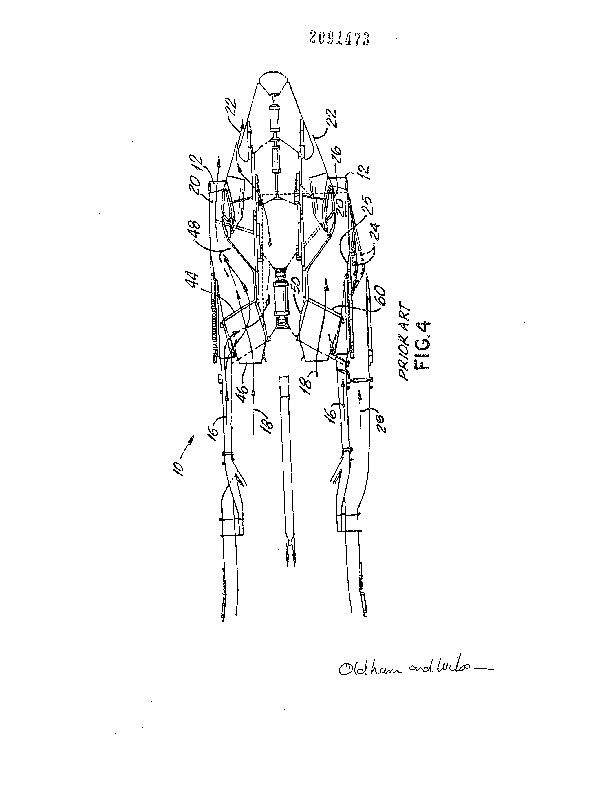
~/~i4~ With the advent of advanced technology noise
suppressors and the variable cycle flade engine concept, the
inner plug or IVP nozzle 22 of Figs. 1, 2 and 3 is no longer
needed to contribut2 to noise suppression. With the
conventional flade design shown in Fig. 4, engine high-
flowing compensates for the lack of a coannular exhaust
system such as shown in Figs~ 1, 2 and 3.
The flade engine configuration of Fig. 5 includes just
two exhaust nozzles, i.e., the variable area flade nozzle 24
for a flade fan, and primary no~zle 26 for the variable
cycle engine. The variable cycle engine es~entially drives
~ ~5~ 3 13DV-10563
the flade fan which exhausts ~lade air 28 through flade
exhaust nozz~e 24u Core air 18 combines with bypass air 16
and ~*~g~ through primary exhaust ducts 25.
~ During takeoff, only the variable cycle engine nozzle
26 requires a mechanical noise suppressor 12. With the
nozzle 26 fitted with a noise suppressor 12, enyine thrust
can be modulated in two ways. First, by modulation o~ the
flade fan operating line and second, by simultaneous
modulation of both the variable cycle engine augmenter
lo temperature rise and variable cycle engine nozzle pressure
ratio. The variable cycle engine exhaust temperature and
pressure must change simultaneously in order to maintain a
variable cycle engine nozzle area 20 ~ixed by the size ~f
mechanical noise suppressor 12.
lS Takeoff thrust power settings are relatiYely low, about
70% of maximum thrust capability, in order to reduce exhaust
velocity and thereby reduce engine noise. Hence, the use of
an afterburner is severely limited for thrust modulation
since afterburners are generally used at power settings of
about 70% of maximum thrust or higher.
Since the flade fan pre sure ratio is low to begin with
in order to provide ~upplemental thrust with low noise, and
~lade fan airflow is only about one-half that of the
variable cycle engine, even large changes in the flade fan
pressure ratio relative to its design pressure ratio result
in little thrust variation. The fan pressure ratio is
generally defined as the ratio of the total pressure of air
a fan to the total pressure of air entering the
~/~S~ ~/3l~2 fan. J
Accordingly, a method and apparatus are needed to
throttle a variable cycle engine of the general type
illustrated in Yigr 4 while the engine operates ef~iciently
at constant maximum airflow. Such throttling is desired in
order to reduce engine noise during takeoff.
4 ~ 7 3 l3DV-l0563
~UMMARY OF T~ XNVENTION
The present invention has been developed to fulfill the
needs not~d above and there~ore has as an object the
provision of a variable cycle aircraft engine which is
capable of modulating thrust and suppressing nois~ beyond
the range presently achievable with mechanical noise
suppr~ssors.
Another object of the invention is to extend the range
of thrust modulation of a variable cycle engine while
maintaining a constant maximum air~low through the engine
since the core engine is designed to achieve maximum noise
suppression at maximum airflowO
Still another object of the invention is to modulate
the thrust of a high~flowing variabl2 cycle engine having a
fixed exhaust nozzle throat area.
~ nother object of the invention is to reduee the mass
located at the rear of a variable cycle engine nozzle plug
and thereby reduce the bending and shear loads experienced
by the internal exhaust nozzle support ~tr~cture and the
engine rear support structure and particularly the struts of
such support structures. ~y reducing such loading, the
cross section of the struts which support the nozzle plug
may be reduced, thereby reducing the o~struction to flow
through the primary flowpath. This in turn reduces pressure
losses in the primary flowpath during acceleration and
cruise operations.
Briefly, the invention is directed to a variable cycle
engine having a variable area valve or injector provided
between a primary duct ~or exhausting relatively high
pressure ~an bypass air and a flade ~ through which
passes relatively low pressure ~lade alr~low. This
arrangement increases the amount of thrust modulation ~/~/$~
available to a high-flowing engine having a fixed exhaust
nozzle throat area. ~fi/f
~J ~ 3
~ 13DV-10563
The aforementioned objects, features and advantages of
the invention will, in part, be pointed out with
particularity, and will, in part, become obvious from the
following more detailed description of the invention, taken
S in conjunction with the accompanying drawi~gs, which form an
integral part thereof.
BRIEF DE~CRIPTION OF ~r~iE DRAWING~
In The Drzlwing3:
Fig. 1 is a schematic partial half section view in
axial section through the exhaust system of a prior art
variable cycle engine as con~igured during takeof;
Fig. 2 is a view of Fig. 1 as configured during
acceleration;
Fig. 3 is a view of Fig . 1 as configured during
supersonic cruise;
Fig. 4 is a schematic partial view in axial section
through the exhaust system of a prior art variable cycle
engine o~ the fan-on-blade or flad~ type;
Fi~. 5 is a schematic partial half view in axial
section through the exhaust system of a flade type variable
cycle engine provided with a bypass valve in accordance with
the present invention;
Fig. 6 is a schematic ~ull view in axial section
~hrough an entire flade engine similar to that of Fig. 5;
Fig. 7 is a fragmental perspective view of a speci~ic
embodiment of a bypass injector door system according to the
invention;
Fig. 8 i~ a plan view of Fig. 7;
Fig. 9 is a ~ragmental schematic view of one of the
injector doors o~ Figs. 7 and 8 showing the axial
reciprocating movement of the door; and
Fig. 10 is a fragmental schematic view of another
embodiment o~ a bypass injector door system according to the
invention.
2 ~ 7 3
13DV-105~3
In the various figur~s of the drawing, like reference
characters designate like parts.
DETAI~E~D DE:8CR:CPTIOM OF T~E PREFERRED EMBODIMENT
The present invention will now be described in
conjunction with Figs. 5 and 6, which illustrake a variable
cycle engine 10, of the flade type. Engine 10 is of the
same general construction as that of Fig. 4, except for the
provision of a bypass valve or bypass injector 30~ Bypass
valve 30 is radially interposed between the relatively high
pressure, high velocity, ~an bypass air 16 flowing through
variable cycle engine bypass duct 32 and the relatively low
pressure, low velocit.y flade air 28 flowing through flade
duct 34.
As seen in Fig. 6, the flade engine 10 is essentially a
standard variable cycle engine with a flade ~an 11 attached
to the primary fan 13. Flade airflow 28 i~ controlled by
opening and closing a variable inlet vane 15 at the flade
rotor inlet 17. Flade exit air 28 then flows through flade
duct 34 which i5 separated from the primary core engine.
The general pattern of exhaust flow as illustrated in
Fig. 5 includes a primary stream of core air 18 exiting a
core engine portion of the variable cycle engine 10 through
primary exhaust duct 25. Core air 18 sombines with at least
a portion of high pressure fan bypass air 16 which enters
the primary exhaust duct 25 via primary valve 27. This
combined flow exits as primary exhaust stream 14 via exhaust
nozzle area 20 of variable cycle engine nozzle 26 and
through mechanical noise suppressors 12.
When bypass valve 30 is opened during takeo~f, a
portion of bypass air 16 is mixed with the flade air 28 and
exits throu~h variable area nozzle 24. ~hen bypass valve 30
is closed, the engine lo of Fig. 5 functions in a manner
generally the same as the engine o~ Fig. 4, except for some
variations in the nozzle plug 48 as discussed below.
_ 7 _ ~~ 73
13DV 10563
Although many configurations are possible for bypass
valve 30, Fig. 5 illustrates a hinged door 36, selectively
pivotable about its forward end portion by a powered hinge
38 which may be controlled or actuated by motor 40. Such a
general valve configuration is well known, although its
specific function and location as described herein is not.
As the bypass valve 30 is selectively opened by pivoting the
hinged door 36 radially outwardly, fan bypass air 16 flows
into the flade duct 34 and mixes with the flade air 28.
The primary purpose of the variable area bypass valve
30 is to extend the range of thrust modulation beyond that
available by other means while maintaini~g constant high-
~lowing airflow from the engine fan which is provided with
an exhaust nozzle having a ~ixed throat area 20. This is
achieved by channeling variable cycle engine bypass airflow
16 from the variable cycle bypass duct 32 into the flade
duct 34 by opening a port such as hinged door 36.
By hinging the forward end of door 36 at the foxward
end of the opening 42, the aft free end or trailing edge 52
of door 36 can pivot in a stable manner into the flade duct
34~ This will result in constant area mixiny of the two
~lo~s 16, 28.
Assuming the afterburner is not operating, as variable
cycle engine bypass ~low 16 is removed from the variable
cycle engine, the mixed flow 14 exiting the variable cycle
engine is allowed more expansionO as there is less mixed
~low due to removal of fan bypass air 16 from t~e primary
exhaust nozzle stream 14 via bypass valve 30. This in turn
results in a lower primary variable cycle nozzle pressure
ratio, lower thrust and less exhaust noise~
The variabla cycle engine bypass air 16 entering the
~lade duct 34 is at a higher pressure than the ~lade duct
air 28 because the variable cycle engine has a higher ~an
pressure ratio than the flade. The mixing o~ these two
- 8 2~ 73
13DV-10563
streams 16, 2~ results in a mixed pressure which is lower
than what the mass averaged pressure would be due to non-
ideal mixing. This phenomenon is known as a dump loss.
This dump loss reduces engine thrust below that which
would occur if the bypass air 16 were expanded through a
nozzle without mixing with the flade ~ir 28. Hence, the
extended thrust modulation range occurs from a change in the
variable cycle engine nozzle pressure ratlo rang~ and the
dump lo~s resulting from mixing two airstreams of unequal
pressures.
As seen in Fig. 6, this method of thrust modulation or
thrust reduction provides an added benefit by reducing the
bending and shear loads applied to both the internal exhaust
nozzle support structure 44 and the engine rear support
structure 46. This is made possible by a reduction in the
mass flow past the IVP nozzle 22 (Fig. 4~, as flow is
diverted away ~rom the IYP nozzle area by bypas~ valve 30.
This allows for the design o~ a smaller IVP nozzle, or as
shown in Figs. 5 and 6, the complete elimination oP the IVP
nozzle 22.
Such downsiæing or elimination of IVP nozzle 22 reduces
the mass located at the rear portion of the nozzle plug 48.
In one embod.iment, elimination o~ IVP nozzle 22 resulted in
a weight reduction of about 148 pounds and a moment
reduction of about 17,760 pound inches on the nozzle struts.
Elimination of the IVP nozzle is possible because the
flade exhaust air 28 provides a large volume of low velocity
air partially surrounding the primary exhaust stream ~8.
Since the flade fan pressure ratio i~ lower than the primary
fan pressure ratio, the flade exhaust air will also slow the
primary core stream 18 as they mix upon exiting the engine
10. Since the volume of Plade air is so much greater than
that which would be channeled to the IVP nozzle 22, any
9 ~ ~3 ~ 3
13DV-1056'
additional air through an acoustic IVP nozzle would provide
insignificant noise reduction.
Since the byp~ss ~ 30 allows for channeling fan
bypass air 16 into the fiade duct 34 and away from the j~*
primary nozzle 26, just as the IVP nozzle 22 did in prior ~ 7
designs, thrust modulation is attained with bypass valve 30.
Hence, the IVP nozzle 22 of Fig. 4 is no longer necessary.
For these reasons, it is advantageous to remove the IVP
nozzle 22 and thus reduce the overall complexity of the
lo exhaust system.
Moreover, as the present invention does not re~uire as
much fan bypass air 16 to be directed into the nozzle plug
48, the hollow struts 50 which support the nozzle plug may
be downsized. In particular, the internal open section of
the struts 50 o~ Fig. 5 only carry sufficient airflow for
pressurization of the nozzle plug 48. This allows the cross
section of the struts 50 to be reduced, thereby reducing the
pressure losses in the primary exhaust nozzle stream 14 due
to blockage or obstruction to flow by the struts.
It can be appreciated that the actuation o~ bypass
valve 30 provides for a reduction in exhaust velocity while
the variable cycle engine 10 maintains a constant high-
flowing (maximum) airflow. This enhances the takeof~ flow
holding performance of the flade. The high pressure flow of
fan bypass air 16 is dissipated while the ~an is kept
running efficiently at full speed so that the exhaust
velocity and the nozzle pressure ratio are reduced along
with a reduction in exhaust noise.
The door 32 in Fig. 5, when opened, increases the Mach
30~ number of the flow thxough the flade duct adjacent the
trailing edge 52 of door 36. This reduces the static
pressure in this region and results in a greater pressure
dump loss thereby further reducing the nozzle pressure
ratio. As noted above, the bypass valve 30 i~ typically
- lo - ~ 3 13DV-10563
opened during takeoff to reduce engine thrust and exhaust
noise. It is typically closed during cruising operations to
provide maximum engine thrust.
There has been disclosed heretofore the best embodiment
of the invention presently contemplated. However, it is to
be understood that various changes and modifications may be
made thereto without departing from the spirit of the
invention. For example, although a pivoting door 36 is
shown in Figs. 5 and 6, the bypa5s valve 20 may take the
form of a linearly axially sliding doors 54 as shown in
Figs. 7, 8 and 9,, or a circumf~rentially rotating sliding
door as shown in Fig. 10.
Doors 54 in Figs. 7, 8 and 9 may be simultaneously
actuated in a coordinated manner via connecting ring ~6
which interconnects each door. Linear a~tuators 58 are
connected to ring 56 to selectiveiy move each door 54
axially back and forth over the primary engine bypass duct
casing 60. Ports 62 are formed through casing fiO to admit
bypass air 16 into flade duct 34 to mix with flade air 28.
In Fig. 9, doors 54 are shown about 80% closed in solid, and
100% open in phantom. Directional arrow 64 indicates the
direction of movement of doors 54.
Another arrangement for bypass valve 30 is shown in
Fig. 10 wherein circumferentially rotating sliding annular
track 66 is tangentially actuated via linear actuators 58.
Actuators 58 are c~nnected to track 66 via connecting arms
68. Track 66 is formed with a plurality of
circumferentially spaced apertures 70 which may be
circumferentially rotated into partial, f~ll or no overlap
with ports 62 formed in casing 60. In this manner, variable
area openings are ~electively effected via selective
actuation of actuators 58 for the entry o~ bypass air 16
from duct 32 into flade duct 34.