Language selection

Search

Patent 2091580 Summary

Third-party information liability

Some of the information on this Web page has been provided by external sources. The Government of Canada is not responsible for the accuracy, reliability or currency of the information supplied by external sources. Users wishing to rely upon this information should consult directly with the source of the information. Content provided by external sources is not subject to official languages, privacy and accessibility requirements.

Claims and Abstract availability

Any discrepancies in the text and image of the Claims and Abstract are due to differing posting times. Text of the Claims and Abstract are posted:

  • At the time the application is open to public inspection;
  • At the time of issue of the patent (grant).
(12) Patent Application: (11) CA 2091580
(54) English Title: CHAMBER FILTER PRESS
(54) French Title: FILTRE-PRESSE A PLATEAUX CHAMBRES
Status: Deemed Abandoned and Beyond the Period of Reinstatement - Pending Response to Notice of Disregarded Communication
Bibliographic Data
(51) International Patent Classification (IPC):
  • B01D 25/164 (2006.01)
  • B01D 25/19 (2006.01)
(72) Inventors :
  • FRESENIUS, JURGEN (Germany)
(73) Owners :
  • PASSAVANT-WERKE AG
(71) Applicants :
  • PASSAVANT-WERKE AG (Germany)
(74) Agent: SMART & BIGGAR LP
(74) Associate agent:
(45) Issued:
(22) Filed Date: 1993-03-11
(41) Open to Public Inspection: 1993-09-21
Availability of licence: N/A
Dedicated to the Public: N/A
(25) Language of filing: English

Patent Cooperation Treaty (PCT): No

(30) Application Priority Data:
Application No. Country/Territory Date
G 92 03 784 (Germany) 1992-03-20

Abstracts

English Abstract


Abstract of the Disclosure
A chamber filter press for dewatering waste water or product
sludges, comprises a press frame with a number of filter plates
movably attached at the head bracket and a crosshead that is
hydraulically movable for closing the filter plate bundle. The
hydraulic cylinder is supported by a replaceable receptacle
device in the form of a flange pipe on the end stand of the press
frame. Both flanges of the tubular receptacle device are annular
flanges, with dimensions matching the flange of the hydraulic
cylinder and they have identical through-bores. The flanges are
permitted to pass through the hydraulic cylinder and the end
stand has on the attachment side a through-hole for the hydraulic
cylinder. The receptacle opening has on the opposite side an
installation opening through which the back end of the hydraulic
cylinder passes.


Claims

Note: Claims are shown in the official language in which they were submitted.

Claims
1. Chamber filter press for dewatering waste water or product sludges, comprising a press
frame with a number of filter plates attached movably at the head bracket and a
crosshead that is movable via a hydraulic cylinder for closing the filter plate bundle,
whereby the hydraulic cylinder is supported via a replaceable receptacle device in the
form of a flange pipe on the end stand of the press frame,
characterized in that both flanges (10, 12) of the tubular receptacle device (11, 11') are
annular flanges, with dimensions matching the flange of the hydraulic cylinder (8) and
identical through-bores, whereby those flanges permit passing through of the hydraulic
cylinder (8), and that the end stand (2) has on the attachment side (13) a through-hole for
the hydraulic cylinder (8) and for attaching the receptacle opening (11, 11'), and has on
the opposite side (14) an installation opening (15) through which the back end of the
hydraulic cylinder (8) passes.

Description

Note: Descriptions are shown in the official language in which they were submitted.


209~580
CHAMBER FILTE~ PRESS
The invention relates to a chamber filter press for dewatering waste water or product sludges.
Such chamber filter presses consist of a press frame with two stands and a head bracket and a
number of filter plates attached movably at the head bracket. A hydraulically operated crosshead
presses the plate bundle together during operation.
Applications exist where the flter press must be operated with a small numbes of pla~es in the
first removal phase and later must be re~ltted with additional plates. It is not very logical to
construct such a long hydraulic cylinder that it closes each plate bundle used during operation.
The piston rod of such a hydraulic cylinder certainly would not be sufficiently buckle-proof.
A remedy to this, that was already suggested, consisted of attaching an extension to the piston
rod that is removed again when the platei number is increased. But this does not solve the
problem of buckle reisistance.
~'" '' ' ''~ '
.. .. ..
^
- , ,: - : .
., - , :. :, .
;- ; ::: :: ::
. , , . . . . . , . : . . . . .. :: . .. .. -.: : .

2091~80
Anolher suggestion to remedy this problem is to set the hydralllic cylinder onto a tubular
receptacle device that is attached removably to the end stand. But this receptacle device also is
not the best solution. The reason for this is that it is only possible to set the hydraulic cylinder
into a receptacle device that has at least the same length, or to attach it without a receptacle
device directly to the end stand. There are no intermediate solutions. The task of finding a
remedy for this is solved according to the invention in that both flanges of the tubular receptacle
device are annular flanges--with dimensions matching the flange of the hydraulic cylinder and
identical through-bores--that permit the passing through of the hydraulic cylinder, and that the
end stand has on the attachment side a through-hole for the hydraulic cylinder and on the
opposite side an installation opening or through-hole for the hydraulic cylinder.
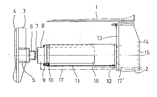
Figures 1 and 2 show a filter press constructed as an embodiment of this invention in two
positions of the hydraulic cylinder, whereby only the head bracket 1 and end stand 2 of the press
frame are visible, and only the crosshead 3 and the first plate 4 of the plate bundle are visible.
The crosshead 3 has a pressure piece 5 to which the head 6 of the piston rod 7 is attached. The
hydraulic cylinder 8 itself is screwed with its flange 9 to the exterior annular flange 10 of the
tubular receptacle device 11. The back end of the receptacle device is screwed with its ring
flange 12 to the attachment side 13 of the end stand 2, whereby the reinforcement 14 at the
opposite side of the stand is equipped with an installation opening lS that can be closed with a
cover after use.
.. ..
. , . ,. . . ~. .: :.
. . . ~.: : : -
- . ~ : ... ,: ,. . .
,; ' , ' , . '

~091580
~ . Ith an initial small number of plates (Fig. 1), the receptacle device is so long that the cylinder
8 still ends inside it. For this purpose, the receptacle device has at its back end a bore 16
through which a hydraulic line 17 is passed. The other hydraulic line 17' for retracting the
crosshead 3 extends parallel to the cylinder, also through the end stand 2, and ends at its head.
As soon as the filter press is increased by additional filter plates, the receptacle device 11 is
detached and replaced with a shorter one 11' (Fig. 2). The latter can be so short that the back
end of the hydraulic cylinder projects into the end stand 2 so that the hydraulic line 17 must be
connected through installation opening 15. The other hydraulic line 17' is shortened
respectively.
The filter press can also be brought immediately to the full number of plates. In this case the
receptacle device 11' is completely removed and the hydraulic cylinder is installed at the end
stand. It then projects through the installation opening 15 to the outside (not shown).
;,, . ~; ',,
.'. ` ~ .
,~ . . .
; - - :; ~ . . : .
.: .. .: . . . .. . :~, ;, ~ .
- . . - , - . . .;, .. : : : .. . . ...
, , : - ,: ;: .
, , ~ : .- . : . ..

Representative Drawing
A single figure which represents the drawing illustrating the invention.
Administrative Status

2024-08-01:As part of the Next Generation Patents (NGP) transition, the Canadian Patents Database (CPD) now contains a more detailed Event History, which replicates the Event Log of our new back-office solution.

Please note that "Inactive:" events refers to events no longer in use in our new back-office solution.

For a clearer understanding of the status of the application/patent presented on this page, the site Disclaimer , as well as the definitions for Patent , Event History , Maintenance Fee  and Payment History  should be consulted.

Event History

Description Date
Inactive: IPC expired 2019-01-01
Inactive: IPC from MCD 2006-03-11
Time Limit for Reversal Expired 1995-09-11
Application Not Reinstated by Deadline 1995-09-11
Deemed Abandoned - Failure to Respond to Maintenance Fee Notice 1995-03-13
Inactive: Adhoc Request Documented 1995-03-13
Application Published (Open to Public Inspection) 1993-09-21

Abandonment History

Abandonment Date Reason Reinstatement Date
1995-03-13
Owners on Record

Note: Records showing the ownership history in alphabetical order.

Current Owners on Record
PASSAVANT-WERKE AG
Past Owners on Record
JURGEN FRESENIUS
Past Owners that do not appear in the "Owners on Record" listing will appear in other documentation within the application.
Documents

To view selected files, please enter reCAPTCHA code :


To view images, click a link in the Document Description column. To download the documents, select one or more checkboxes in the first column and then click the "Download Selected in PDF format (Zip Archive)" or the "Download Selected as Single PDF" button.

List of published and non-published patent-specific documents on the CPD .

If you have any difficulty accessing content, you can call the Client Service Centre at 1-866-997-1936 or send them an e-mail at CIPO Client Service Centre.


Document
Description 
Date
(yyyy-mm-dd) 
Number of pages   Size of Image (KB) 
Cover Page 1993-09-21 1 25
Claims 1993-09-21 1 27
Abstract 1993-09-21 1 23
Drawings 1993-09-21 1 30
Descriptions 1993-09-21 3 94
Representative drawing 1998-08-26 1 12