Language selection

Search

Patent 2091744 Summary

Third-party information liability

Some of the information on this Web page has been provided by external sources. The Government of Canada is not responsible for the accuracy, reliability or currency of the information supplied by external sources. Users wishing to rely upon this information should consult directly with the source of the information. Content provided by external sources is not subject to official languages, privacy and accessibility requirements.

Claims and Abstract availability

Any discrepancies in the text and image of the Claims and Abstract are due to differing posting times. Text of the Claims and Abstract are posted:

  • At the time the application is open to public inspection;
  • At the time of issue of the patent (grant).
(12) Patent: (11) CA 2091744
(54) English Title: BRACKET FOR HOLDING CEILING SUSPENDED FIXTURES
(54) French Title: PATTE DE FIXATION POUR ACCESSOIRES SUSPENDUS AU PLAFOND
Status: Term Expired - Post Grant Beyond Limit
Bibliographic Data
(51) International Patent Classification (IPC):
  • E04B 9/18 (2006.01)
  • A47B 96/06 (2006.01)
(72) Inventors :
  • FLORENT, BERTRAND (Canada)
  • PROULX, ROGER (Canada)
(73) Owners :
  • BERTRAND FLORENT
(71) Applicants :
  • BERTRAND FLORENT (Canada)
(74) Agent: LAVERY, DE BILLY, LLP
(74) Associate agent:
(45) Issued: 2005-09-13
(22) Filed Date: 1993-03-16
(41) Open to Public Inspection: 1993-04-16
Examination requested: 2000-01-11
Availability of licence: N/A
Dedicated to the Public: N/A
(25) Language of filing: English

Patent Cooperation Treaty (PCT): No

(30) Application Priority Data: None

Abstracts

English Abstract

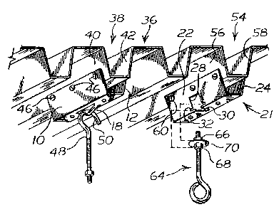
A ceiling mounted bracket is adapted to be fixed under a corrugated ceiling formed of U-shaped channels having flaring sides. The bracket which has a U-shaped cross-section corresponding to one channel is formed of two lateral faces and a joining face provided with a perforation suitable for hanging a ceiling fixture.


French Abstract

Un support de fixation au plafond est adapté pour être fixé sous un plafond ondulé formé de profilés en U ayant des côtés évasés. Le support, qui présente une section transversale en forme de U correspondant à un profilé, est formé de deux faces latérales et d'une face de liaison comportant une perforation convenant à la suspension d'un plafonnier.

Claims

Note: Claims are shown in the official language in which they were submitted.


CLAIMS
1. A mounting bracket to be fixed under a ceiling made
of sheet material and formed with adjacent U-shaped channels
each having two outwardly flaring flat side walls and a bottom
flat wall interconnecting said two flat side walls, wherein:
said mounting bracket is made of sheet material;
said mounting bracket has a generally U-shaped cross-
section formed by two lateral flat members and a joining
member interconnecting said two lateral members;
said two lateral flat members flare outwardly to
angularly correspond to said two flat side walls to be applied
to said two flat side walls, respectively;
said bottom flat wall has a first width and said joining
member has a second width narrower than said first width
whereby said joining member is spaced apart from said bottom
flat wall when said two flat lateral members are applied to
said two flat side walls, respectively;
said two lateral members comprise means for securing said
two lateral members to the two flat side walls of one of the
U-shaped channels, respectively; and
at least one of said joining member and lateral members
comprises means for attaching to said mounting bracket a
ceiling-supported fixture.
2. The mounting bracket as recited in claim 1, in which
said attaching means comprises said joining member provided
with two substantially parallel cuts to enable deformation of
a rectangular portion of said joining member into a downward
generally V-shaped hook integral with said joining member.
3. The mounting bracket as recited in claim 2, wherein
said joining member is elongate and wherein said cuts and
downward hook are longitudinal.

4. The mounting bracket as recited in claim 1, wherein
said attaching means comprises said joining member and one of
said two lateral flat members provided with a slot perforated
through both said joining member and said one lateral flat
member, and said one lateral flat member is provided with a
widened extension of said slot for enabling insertion of a
fastener device to be mounted in said slot, said fastener
device extending in a space between said joining member and
said bottom flat wall.
5. The mounting bracket as recited in claim 4, wherein
said widened extension of the slot is remote from said joining
member whereby said one lateral flat member defines a shoulder
on each side of the slot.

Description

Note: Descriptions are shown in the official language in which they were submitted.


TITLE OF THE INVENTION
BRACKET FOR HOLDING CEILING SUSPENDED FIXTURES
BACKGROUND OF THE INVENTION
Field of the invention
The invention is directed to a mounting bracket adapted to
be mounted on a corrugated ceiling so as to support a light, a
fan or similar ceiling fixtures. The mounting bracket has a
ga_neraliy U-shaped cross-section with legs flaring outwardly so
as to generally correspond to the shape of a corrugation in the
ceiling. The bracket is particularly provided with an opening for
hooking the ceiling fixture.
Prior art
United States patent No. 3,022,033 issued on Febraury 20,
1962 describes a service bracket having a generally U--shape
cross-section extending on both sides with flanges. The flanges
are adapted to abut against a wall and be retained thereto by a
screw extending through the Elat apex face of the U-shaped cross-
section. An opening extending completely through both sides of
the U-shaped cross-section allows the extension of an attaching
bail of a service line.
United States patent No. 4,978,092 is directed to a
universal support bracket for attaclument to the back of an
electrical box. The bracket is particularly characterized by
flanges which are adapted to be bent to take into consideration
the. thickness of an electrical box or the depth of a wall.
structure.

2~91~44
-2-
Another universal bracket is disclosed in United States
patent No. 4,787,587 which includes at least one opening for
receiving a fastener on a flat portion thereof. A second flat
portion is provided with a notch and a third flat portion forcas
an obtuse angle with the second flat portion. Such a bracket
would not be suitable for supporting a light fixture on a
corrugated surface.
SUMMARY OF THE INVENTION
The mounting bracket according to the invention is adapted
to be mounted on a ceiling formed of adjacent U-shaped channels
having flaring sides. The bracket has a generally U-shaped
cross-section formed by two lateral flat faces and a joining flat
face between the lateral faces. The lateral faces are flaring
outwardly to angularly correspond to the flaring sides of the
channels and to abut thereagainst. The lateral sides of the
bracket are provided with holes to receive fastening means for
securing the bracket to the channels. The joining face between
the two lateral faces is provided with a perforation to allow a
ceiling fixture to be hooked therefrom.
In one embodiment, the joining face has a rectangular
portion deformed downwardly for forming a V-shaped hook extending
croraswise relative to the U-shaped cross-section of the bracket.
In another embodiment, the joining face and one of the
lateral faces have a perforated slot extending towards each other
to define a common opening through both the lateral face and the
joining face. A transverse slot across the perforated slot in

209~.~~4
-3-
the lateral face and at a level above the joining face defines a
shoulder on each side of the opening. This opening is adapted to
allow the sideways passage of a fastening device and of a washer
through the transversal slot for allowing the washer to sit
behind the shoulder and be retained thereby.
BRIEF DESCRIPTION OF THE DRAWINGS
Figure i is a perspective view of one embodiment of the
bracket according to the invention,
Figure 2 is a perspective view of another embodiment of the
bracket,
Figure 3 illustrates the brackets shown in figures 1 and 2
secured to a corrugated ceiling,
Figure 4 illustrates a perspective botCom view of a corruga-
ted ceiling supported by a frame structure,
Figure 5 is a cross-sectional view along line 5-5 shown in
figure 4, and
Figures 6 and 7 illustrate two different embodiments of
brackets according to the invention adapted to be supported by
the frame shown in figures 4 and 5.
DL~TAILED_D.E.SCRIPTION-OFuTHE--INVENTION
Figure 1 illustrates a bracket according to the invention
having a U-shaped cross-section formed 'oy a pair of lateral faces
and 12 and a joining face 14. The lateral faces 10 and 12 are
flaring outwardly from tile joining face 14 at a predetermined
angle to be explained later. The joining face 14 is provided
with a perforation obtained by sufficiently deforming the

~~917~~
_LF_
material of the joining face 14 to produce a transversal
perforation 16. For this purpose, the joining face 14 is punched
downwardly with a triangular punch which is applied over a
rectangular surface in joining face 14, the apex of the
triangular punch being adapted to break the material of the
joining face 14 and produce a generally triangular perforation
16. The apex 20 of the strip 18 will serve to support a suitable
hook passing through the perforation 16 as explained later.
The embodiment shown in figure 2, is similarly characterized
by two lateral faces 22 and 24 flaring outwardly from a joining
face 26 to generally form a U-shaped cross-section. The lateral
face 22 is provided with a downward slot 28 continuously
extending through a slot 30 in the joining face 26. A
transversal slot 22 is preferably provided through the lateral
face 22 at a level adjacent and above the joining face 26 to form
a shoulder 34 for a purpose explained later.
The brackets illustrated in figures 1 and 2 are shown in
figure 3 fixed under a corrugated ceiling 36. The corrugated
ceiling 36 is formed of adjacent U-shaped channels having flaring
sides oriented at an angle substantially corresponding to the
angl.r_ of the flaring lateral faces of the brackets illustrated in
figures 7. and 2.
The bracket illustrated in figure 1 is mounted in a
straddling arrangement over channel 38 formed by two flaring
sides 40 and 42 at an angle substantially corresponding to the
an~le of the f-1ar ng faces 7.0 and 12. The lateral faces 10 and

~0~~7~~
-5-
12 are provided with a set of holes 44 adapted to receive screws
46 for securing the lateral faces 10 and 12 on the sides 40 and
42 of the channel 38. When the bracket is fixed to the channel
38, a hook 48 having an open loop 50 can be supported by the
strip 18 about its apex 20. The hook 48 is adapted to support a
ceiling fixture (not shown). The bracket may also be provided
with a pair of openings 52 in the joining face 14. The openings
52 are adapted to allow the passage of electrical wires when the
ceiling fixture is an electrical fixture.
The bracket 2i shown in figure 2, is similarly adapted to be
mounted on a channel 54 of the corrugated ceiling. By straddling
the lateral face 22 and 24 over the sides 56 and 58 of the
channel 54 by a set of screws 60 extending through a set of holes
62 provided in the lateral faces 22 and 24 of the bracket 21.
The slots 28 and 30 are adapted to allow the passage of a hook 64
provided with a pair of nuts 66 and 68 and a washer 70. The
washer 70 is dimensioned to slide through the slot 32 and be
retained inside the bracket 21 by the ciioulder 34 to prevent it
from sliding out. The two nuts 66 and 68 are adapted to be
tightened against the joining face 26 for maintaining the hook 64
secured along the slot 30. It should be understood that the
shoulders 34 and the washer 7U are not compulsory elements when
the nuts 66 and 68 are sufficiently large and tightly secured to
the bracket 21 for the purpose intended.
The brackets described in figures 1 and 2 may have a length
of about 3 to 6 inches and are adapted to support one ceiling
fixture. The same bracket may be mounted daft:erently below the

20~1'~44
_6_
corrugated ceiling because such ceilings are generally supported
by structural frames of the type shown in figures 4 and 5. The
corrugated ceiling 72 is mounted over a structural frame made of
truss beams 74 and 76 disposed transversely relative to the
channels 78 and 80 of the corrugated ceiling 72. With this
arrangement as shown in figures 4 and 5, the bracket 82 according
to the in~rention has a length which exceeds the distance between
the two beams 74 and 76 021 4Jhlch it is supported. The bracket 82
has a length which usually exceeds 6 feet and is mounted between
two adjacent channels 78 and 80 and rests on the upper beams 74a
and 76a of the truss beams 74 and 76. The width of the bracket
82 is dimensioned so as to sidewardly abut against the two
adjacent channels 78 and 80. Such a dimension allows the bracket
82 to be installed by sliding it over the frame 74 and 76 between
two adjacent channels such as 78 and 80.
Considering that brackets such as 82 are relatively long,
they are rigidified with lateral flanges 84 to prevent their
bending between the two adjacent truss beams 74 and 76. The
embodiment of the brackets 82, shown in figure 6, is provided
with flanges 84 extending outwardly relat9.ve to the free edges of
the lateral faces 86 and 88. Another embodiment for the flanges
consists of inwardly projecting flanges 90 relative to the
lateral faces 92 and 94.
The bracket 82 shown in figure 6 is provided with
perforations 96 of the type shown in figure 2 while the bracket
89 shown in figure 7 is provided w:Lth a perforation 98 of the
typo shown i.n ti;urca 1. It should be obvious that tire same

209.744
_, _
bracket may be provided with both types of perforations 96 and 98
along their length.

Representative Drawing
A single figure which represents the drawing illustrating the invention.
Administrative Status

2024-08-01:As part of the Next Generation Patents (NGP) transition, the Canadian Patents Database (CPD) now contains a more detailed Event History, which replicates the Event Log of our new back-office solution.

Please note that "Inactive:" events refers to events no longer in use in our new back-office solution.

For a clearer understanding of the status of the application/patent presented on this page, the site Disclaimer , as well as the definitions for Patent , Event History , Maintenance Fee  and Payment History  should be consulted.

Event History

Description Date
Inactive: Expired (new Act pat) 2013-03-16
Inactive: Payment - Insufficient fee 2007-05-28
Inactive: Reversal of will be deemed expired status 2007-05-28
Inactive: Office letter 2007-03-01
Inactive: Entity size changed 2007-03-01
Inactive: Late MF processed 2007-01-29
Inactive: Corrective payment - s.78.6 Act 2007-01-29
Letter Sent 2006-03-16
Grant by Issuance 2005-09-13
Inactive: Cover page published 2005-09-12
Pre-grant 2005-06-23
Inactive: Final fee received 2005-06-23
Amendment After Allowance (AAA) Received 2005-02-02
Inactive: Amendment after Allowance Fee Processed 2005-02-02
Letter Sent 2005-01-04
Notice of Allowance is Issued 2005-01-04
Inactive: Approved for allowance (AFA) 2004-10-20
Inactive: Adhoc Request Documented 2004-05-25
Withdraw from Allowance 2004-05-25
Inactive: Approved for allowance (AFA) 2004-05-05
Letter Sent 2004-03-16
Amendment Received - Voluntary Amendment 2004-03-16
Inactive: Single transfer 2004-02-18
Inactive: S.30(2) Rules - Examiner requisition 2003-10-08
Inactive: Status info is complete as of Log entry date 2000-02-18
Letter Sent 2000-02-18
Inactive: Application prosecuted on TS as of Log entry date 2000-02-18
All Requirements for Examination Determined Compliant 2000-01-11
Request for Examination Requirements Determined Compliant 2000-01-11
Application Published (Open to Public Inspection) 1993-04-16

Abandonment History

There is no abandonment history.

Maintenance Fee

The last payment was received on 2005-02-10

Note : If the full payment has not been received on or before the date indicated, a further fee may be required which may be one of the following

  • the reinstatement fee;
  • the late payment fee; or
  • additional fee to reverse deemed expiry.

Please refer to the CIPO Patent Fees web page to see all current fee amounts.

Fee History

Fee Type Anniversary Year Due Date Paid Date
MF (application, 5th anniv.) - small 05 1998-03-16 1998-02-17
MF (application, 6th anniv.) - small 06 1999-03-16 1999-01-29
Request for examination - small 2000-01-11
MF (application, 7th anniv.) - small 07 2000-03-16 2000-02-22
MF (application, 8th anniv.) - small 08 2001-03-16 2001-03-09
MF (application, 9th anniv.) - small 09 2002-03-18 2002-03-06
MF (application, 10th anniv.) - small 10 2003-03-17 2003-02-26
Registration of a document 2004-02-18
MF (application, 11th anniv.) - small 11 2004-03-16 2004-02-18
2005-02-02
MF (application, 12th anniv.) - small 12 2005-03-16 2005-02-10
Final fee - small 2005-06-23
MF (patent, 13th anniv.) - standard 2006-03-16 2006-02-14
Reversal of deemed expiry 2006-03-16 2006-02-14
2007-01-29
MF (patent, 14th anniv.) - standard 2007-03-16 2007-02-12
MF (patent, 15th anniv.) - standard 2008-03-17 2008-03-14
MF (patent, 16th anniv.) - standard 2009-03-16 2009-02-19
MF (patent, 17th anniv.) - standard 2010-03-16 2010-02-26
MF (patent, 18th anniv.) - standard 2011-03-16 2011-02-10
MF (patent, 19th anniv.) - standard 2012-03-16 2012-03-12
Owners on Record

Note: Records showing the ownership history in alphabetical order.

Current Owners on Record
BERTRAND FLORENT
Past Owners on Record
ROGER PROULX
Past Owners that do not appear in the "Owners on Record" listing will appear in other documentation within the application.
Documents

To view selected files, please enter reCAPTCHA code :


To view images, click a link in the Document Description column. To download the documents, select one or more checkboxes in the first column and then click the "Download Selected in PDF format (Zip Archive)" or the "Download Selected as Single PDF" button.

List of published and non-published patent-specific documents on the CPD .

If you have any difficulty accessing content, you can call the Client Service Centre at 1-866-997-1936 or send them an e-mail at CIPO Client Service Centre.


Document
Description 
Date
(yyyy-mm-dd) 
Number of pages   Size of Image (KB) 
Representative drawing 1999-02-18 1 20
Cover Page 1994-04-01 1 13
Abstract 1994-04-01 1 8
Claims 1994-04-01 2 32
Drawings 1994-04-01 2 79
Description 1994-04-01 7 170
Claims 2004-03-16 2 73
Representative drawing 2004-05-05 1 21
Claims 2005-02-02 2 59
Cover Page 2005-08-16 1 44
Reminder - Request for Examination 1999-11-17 1 117
Acknowledgement of Request for Examination 2000-02-18 1 180
Courtesy - Certificate of registration (related document(s)) 2004-03-16 1 105
Commissioner's Notice - Application Found Allowable 2005-01-04 1 161
Maintenance Fee Notice 2007-05-28 1 173
Late Payment Acknowledgement 2007-05-29 1 166
Maintenance Fee Notice 2007-05-28 1 173
Correspondence 1994-10-19 3 96
Fees 2003-02-26 1 41
Fees 1998-02-17 1 47
Fees 1999-01-29 1 46
Fees 2001-03-09 1 39
Fees 2002-03-06 1 40
Fees 2000-02-22 1 38
Fees 2004-02-18 1 35
Correspondence 2005-03-31 1 15
Fees 2005-02-10 1 36
Correspondence 2005-06-23 1 27
Fees 2006-02-14 1 43
Fees 2007-01-29 1 42
Correspondence 2007-03-01 1 14
Fees 2007-02-12 1 44
Fees 2008-03-14 1 44
Fees 2009-02-19 1 45
Fees 1997-02-17 1 47
Fees 1996-03-13 1 32
Fees 1995-03-01 1 34