Note: Descriptions are shown in the official language in which they were submitted.
2~9~,OJ,
-1- 760-23
IMPROVED SWITCH ACTUATING ASSEMBLY
IN A CIRCUIT BREAKER PANELBOARD
BACKGROUND OF THE I .NTION
Fiend of the Intention
The present invention generally relates to circuit
breaker panelboard installations and, more
particularly, is concerned with an improved circuit
breaker switch actuating assembly in a circuit breaker
panelboard.
ascription of the Prior Art
Circuit breaker installations wired to major
lighting, heating and electrical equipment in
industrial facilities are typically enclosed by
panelboards to provide protection of and restrict
unauthorized access to the circuit breaker switches.
In a typical panelboard installation, the switches are
parts of modules arranged in a pair of parallel
vertical columns. The "on°' and "off" positions of the
switches in one column of modules are opposite to the
"on'° and "off" positions of the switches in the other
column of modules.
One prior art circuit breaker panelboard for
enclosing the columns of circuit breaker modules
20~~O~j
-2- 760-23
includes a rear housing defining a cavity, and a front
cover hingedly mounted to the rear housing for opening
and closing relative thereto. The rear housing
supports the circuit breaker modules in the pair of
parallel columns in the cavity. Thus, the circuit
breaker switches are thereby also arranged in the pair
of parallel columns. The front cover has a plurality
of closely-spaced holes arranged in a pair of vertical
columns. The holes in the vertical columns are
disposed in general alignment with the switches of the
circuit breaker modules in the pair of vertical
columns.
Also, the panelboard includes a plurality of
operating members rotatably mounted through the
plurality of closely-spaced holes of the front cover.
Therefore, the operating members are arranged in a pair
og vertical columns corresponding to the pair of
vertical columns of the holes. One operating member is
provided for each circuit breaker switch. Each
operating member basically includes an elongated shaft
rotatably mounted through a respective one of the holes
in the front cover, a lever or handle attached to an
outer end of the shaft and thereby disposed on the
exterior side of the front cover where it can be
gripped by a user's fingers, and a bifurcated trip arm
attached to an inner end of the shaft and thereby
disposed on the interior side of the front cover. The
bifurcated trip arms are disposed at the same angular
orientation on the elongated shafts of the operating
members.
The bifurcated trip arm of each of the operating
members is releasably coupled directly with one of the
circuit breaker switches. By rotating the handle of an
operating member in one direction, the respective one
switch is moved linearly and arcuately from an "on~'
position to "off°' position, whereas by rotating the
handle of the operating member in the opposite
2~19~,p~?
-3- 760-23
direction the one switch is moved linearly and
arcuately in reverse from the "off°' position to the
"on" position. The handles of the operating members in
one column must be rotated in a direction opposite to
the direction in which the handles of the operating
members in the other column must be rotated in order
for all circuit breaker switches of both columns of
modules to move either to their respective '°on"
positions or to their respective "off" positions. To
protect the operating members from unauthorized
movement, latches are typically mounted to the front
cover for use in locking the handles of the operating
members at the desired one of their "on" or "off"
positions.
There are several major drawbacks with a panelboard
having the above-described construction. One drawback
is that due to the closeness of adjacent operating
members in each of the columns thereof, it is difficult
to easily and quickly grip a desired one of the handles
in order to move a selected one of the circuit breaker
switches between its "on" and '°off'° positions.
Another drawback is that due to the closeness of
the holes in the front cover which mount the operating
members, stresses that are normally induced in the
portions of the front cover surrounding the mounting
holes tend to concentrate at these front cover portions
and initiate cracks which can propagate and cause
premature fractures of the front cover between the
holes. Such fractures can interfere with properly
functioning of the operating members and integrity of
the cover and so typically necessitate replacement of
the front cover and operating members of the
panelboard.
Consequently, a need exists to provide an
improvement of the construction of the above-described
prior art circuit breaker panelboard which will
eliminate the above-described drawbacks of the prior
CA 02092032 2001-07-17
-4-
art without introducing new ones in their place.
SUMMARY OF THE INVENTION
The present invention provides an improved circuit breaker switch actuating
assembly in a circuit breaker panelboard being designed to satisfy the
aforementioned needs. The switch actuating assembly of the present invention
substantially reduces concentration of stresses by increasing the spacing
between
the mounting holes in the front cover of the panelboard. The operating members
and the stresses induced in the front cover by pressures applied to the front
cover
when there is an explosion within the panelboard are distributed or spread
over a
larger area of the front cover. This not only reduces stress concentrations
but also
increases accessibility to a desired one of the operating member handles. The
reduction in stress concentrations will increase the useful life of the front
cover of
the panelboard.
The invention pertains to a circuit breaker actuating assembly in a circuit
breaker panelboard having a housing for mounting a plurality of circuit
breaker
modules with each module having an actuator movable between "on" and "off"
positions, the modules and actuators each being arranged in a pair of spaced
columns, and a cover releasably attachable to the housing for enclosing the
circuit
breaker modules. The circuit breaker actuating assembly comprises: (a) a
plurality
of operating members rotatably mounted to the cover and arranged in first and
second groups; and (b) a plurality of linking members disposed between the
cover
and housing and arranged in first and second groups.
More particularly, the assembly includes a plurality of operating members
rotatably mounted to the cover and arranged in first and second groups, the
operating members of the first group being disposed in a first pair of columns
aligned with the pair of columns of the circuit breaker actuators and provided
in
directly coupled relationship with first alternating ones of the circuit
breaker
actuators in the columns such that selected rotation of the operating members
of
CA 02092032 2001-07-17
-5-
the first group causes selected movement of the first alternating ones of
the circuit breaker actuators. The operating members of the second group
are disposed in a second pair of columns respectively displaced laterally
outwardly from opposite sides of the pair of columns of the circuit breaker
actuators such that the operating members of the second group are spaced
from second alternating ones of the circuit breaker actuators in the
columns. The plurality of linking members are disposed between the cover
and housing and are arranged in first and second groups, the linking
members of the first and second groups respectively extending between
and interconnecting the operating members of the second group and the
second alternating ones of the circuit breaker actuators in the respective
columns so as to provide indirectly coupled relationships therebetween
such that selected rotation of the operating members of the second group
causes selected movement of the linking members and thereby to the
second alternating ones of the circuit breaker actuators.
More particularly, the operating members are equal in number to the
number of circuit breaker switches mounted to the housing and each
operating member corresponds to one of the circuit breaker switches so
that a particular one of the operating members can be selected and rotated
to actuate a desired one of the circuit breaker switches. The linking
members are equal in number to one-half of the number of circuit breaker
switches mounted to the housing.
Further, each operating member includes an elongated shaft rotatably
mounted through the cover, a handle attached to an outer end of the shaft
and disposed on an exterior side of the cover where it can be gripped by
a user's fingers, and a trip arm attached to an inner end of the shaft and
disposed on an interior side of the cover. The trip arm has a
~00?03?
-.6- 760-23
bifurcated configuration. On the one hand, the
bifurcated trip arms of the operating members of the
first group thereof directly interfit respectively with
first alternating ones of the circuit breaker switches
such that rotation of the operating members and their
trip arms causes linear movement of the first
alternating ones of the circuit breaker switches
between the "on" and "off" positions. On the other
hand, the bifurcated trip arms of the operating members
of the second group thereof interfit with ends of the
linking members such that rotation of the operating
members and their trip arms causes linear movement of
the linking members anc'1 of the second alternating ones
of the circuit breaker switches therewith between the
"on" and "off" positions.
Also, the trip arms of the operating members of the
first group thereof are disposed at angular
orientations being opposite-to the angular orientations
of the trip arms of the operating members of the second
group thereof. Further, the linking members of the
first group thereof are disposed at an orientation
being opposite to an orientation of the linking members
of the second group thereof. These orientations result
in all of the handles of the operating members having
the same ~'on" and "off°' positions.
These and other features and advantages and
attainments of the present invention will become
apparent to those skilled in the art upon a reading of
the following detailed description when taken in
conjunction with the drawings wherein there is shown
and described an illustrative embodiment of the
invention.
HRIEF DESCRIPTION OF THE DRA6~IINGS
In the course of the following detailed
description, reference will. be made to the attached
209~~~?
-7- 760--23
drawings in which:
Fig. 1 is a.front elevational view of a circuit
breaker panelboard incorporating an improved circuit
breaker switch actuating assembly of the present
invention, showing those of the components of the
assembly disposed on the exterior side of a front cover
of the panelboard.
Fig. 2 is a front elevational view of the circuit
breaker panelboard incorporating the improved circuit
breaker switch actuating assembly of the present
invention, showing those of the components of the
actuating assembly disposed on the interior side of a
rear housing of the panelboard.
Fig. 3 is an enlarged fragmentary view of a central
region of the rear housing of the panelboard of Fig. 2,
showing those of the components of the actuating
assembly disposed on the respective interior sides of
the front cover and rear housing of the panelboard in
coupled relationship with each other and with the
circuit breaker switches.
Fig. 4 is an enlarged fragmentary view taken along
lines 4--4 of Figs. 1 and 3 through the front cover of
the panelboard, showing in side elevation the
components comprising the actuating assembly disposed
both on the exterior arid interior side of the front
cover and on the interior side of the rear housing of
the panelboard in coupled relationship with each other
and with the circuit breaker switches.
Fig. 5 is a top plan view of the switch actuating
3o assembly as seen along line 5--5 of Fig. 4, showing
handles of operating members of the actuating assembly,
and thereby the circuit breaker switches coupled
thereto, disposed at "off'° positions.
Fig. 6 is a transverse sectional view of the switch
actuating assembly taken along line 6--6 of Fig. 4,
showing the bifurcated trip arms of operating members
and a linking member of the actuating assembly disposed
~09~, 0~;
760-23
at "off" positions.
Fig. 7 is another transverse sectional view of the
switch actuating assembly taken along line 7--7 of
Fig. 4, showing the bifurcated trip arms of the
operating members and the linking member of the
actuating assembly at "off" positions.
Fig. 8 is a top plan view of the switch actuating
assembly similar to that of Fig. 5, but showing handles
of operating members of the actuating assembly, and
thereby the circuit breaker switches coupled thereto,
disposed at "on" positions.
Fig. 9 is a transverse sectional view of the switch
actuating assembly similar to that of Fig. 6, but
showing the bifurcated trip arms of operating members
and the linking member of the actuating assembly
disposed at '°on" positions. '
Fig. 10 is another transverse sectional view of the
switch actuating assembly similar to that of Fig. 7,
but showing the bifurcated trip arms of operating
members and the linking member of the actuating
assembly disposed at "on" positions.
Fig. 11 is a side elevational view of one of the
operating members of the switch actuating assembly of
Fig. 4 by itself.
Fig. 12 is a fragmentary front elevational view of
the operating member of the switch actuating assembly
as seen along line 12--12 of Fig. 1l.
Fig. 13 is a top plan view similar to that of
Fig. 7, showing one of the plurality of linking members
employed in the switch actuating assembly in
conjunction with one of the switch modules.
Fig. 14 is a side elevational view of the linking
member and switch module as seen along line 14--14 of
Fig. 13.
Fig. 15 is a top plan view similar to that of
Fig. 13, showing one of 'the plurality of switch
modules.
~09~0~?
-9- 760-23
Fig. 16 is a side elevational view of the one
switch module as seen along line 16--16 of Fig. 15.
DETAILED DESCRIPTION OF THE INVENTION
In the following description, like reference
characters designate like or corresponding parts
throughout the several views. Also in the following
description, it is to be understood that such terms as
~'forward", '~rearward", "left", "right", '~upwardly~~,
°'downwardly", and the like, are words of convenience
and are not to be construed as limiting terms.
In General
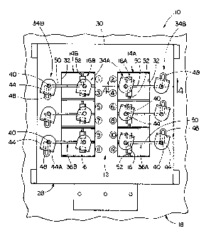
Referring now to the drawings, and particularly to
Figs. 1-3, t:~ere is illustrated a circuit breaker
panelboard, generally designated 10, incorporating an
improved circuit breaker switch actuating assembly,
generally designated 12, in accordance with the present
invention. The circuit breaker panelboard 10 encloses
a plurality of circuit breaker modules 14 arranged at a
circuit breaker installation in a pair of parallel
vertical columns 14A, 148, as seen in Figs. 2 and 3.
The modules 14 have switches 16 also arranged in the
pair of generally parallel spaced apart vertical
columns 16A, 16B. The ~'on" and '°off" positions of the
switches :16A in one column of modules 14A are opposite
to the ~~on" and ~'off~' positions of the switches 16B in
the other column of modules 14B.
The circuit breaker panelboard 10 includes a rear
housing 18 defining a recessed cavity 20, and a front
cover 22 mounted by hinges 24 to the rear housing 18
for pivotal movement relative thereto for opening and
closing access to the cavity 20 of the rear housing 18.
The rear housing 18 and front cover 22 are preferably
releasably attachable together at their respective
20~~03?
-10- 760-23
peripheral rims 18A, 22A by a plurality of bolts 26.
Sealing gaskets (not shown) can be provided between the
peripheral rims 18A, 22A to seal the cavity 20 from the
exterior environment.
The circuit breaker panelboard 10 also includes a
mounting bracket 28 for supporting the circuit breaker
modules 14. The mounting bracket 28 is disposed in the
cavity 20 and attached to the rear housing 18. A front
panel 30 of the mounting bracket 28 defines a pair of
elongated windows 32 in side-by-side spaced relation to
one another. The circuit breaker modules 14 are
mounted to the bracket 28 such that they are arranged
in the pair of parallel columns 14A, 14B and exposed
through the windows 32 thereof. The circuit breaker
switches 16 of the columns of modules 14A, 14B are
thereby correspondingly arranged in the pair of
parallel columns 16A, 168.
Improved Switch Actuatin~~ Assembly of the Invention
Referring to Figs. 1-4, the circuit breaker
panelboard 10 thus includes the rear housing 18
mounting the circuit breaker switches 16 arranged in
the pair of spaced vertical columns 16A, 16B and the
front cover 22 releasably attachable to the rear
housing 18 for enclosing the circuit breaker switches
16. The improved circuit breaker switch actuating
assembly 12 is coupled to the circuit breaker switches
16 and to the front cover 22 for facilitating
manipulation of the switches 16 from the exterior of
the front cover 22.
Referring to Figs. 1-10, the improved switch
actuating assembly 12 of the present invention
incorporated by the above-described circuit breaker
panelboard 10 basically includes a plurality of
operating members 34 mounted to the front cover 22 and
arranged in first and second groups 34A, 34B thereof
20920?
-11- 760-23
and a plurality of linking members 36 disposed between
the front cover 22 and the rear housing 18 and arranged
in first and second groups 36A, 36B thereof. The
operating members 34 are equal in number to the number
of the circuit breaker switches 16 mounted to the rear
housing 18 and each operating member 34 corresponds to
one of the circuit breaker switches 16 so that a
particular one of the operating members 34 can be
selected and rotated to actuate a desired one of the
circuit breaker switches 16.
The operating members 34A of the first group are
disposed in a firstpair of vertical columns aligned
with the pair of vertical columns 16A, 16B of the
circuit breaker switches 16. The operating members 34A
are also provided in directly coupled relationships
with first alternating ones of the circuit breaker
switches 16A, 168 in the pair of vertical columns. The
operating members 34B of the second group are disposed
in a second pair of vertical columns respectively
displaced laterally outwardly from the pair of vertical
columns 16A, 16B of the circuit breaker switches 16.
Thus, the operating members 34B are spaced from the
second alternating ones of the circuit breaker switches
16A, 16B in the pair of columns. The linking members
36A, 36B of the first and second groups extend between
and interconnect the second alternating ones of the
circuit breaker switches 16A, 16B in both vertical
columns and respective operating members 34B of the
second group being disposed in the second pair of
vertical columns. Thus, the linking members 36A, 36B
provide indirect coupled relationships between the
operating members 34B and the second alternating ones
of the circuit breaker switches 16A, 168.
The above-described arrangement of the operating
members 34 permits the provision of a plurality of
spaced holes 38A, 38B arranged in first and second
pairs of vertical columns in the front cover 22 of the
2092Q3?
°12- 760-23
panelboard 10 which correspond to the first and second
pairs of vertical columns of the operating members 34A,
34B for rotatably mounting the operating members 34 to
the front cover 22. The holes 38 are thus arranged
differently and farther apart from one another in the
front cover 22 herein than they are in the prior art
construction described in the background section of the
application. As seen in Fig. 3, only the holes 38A in
the first pair of, vertical columns are disposed in
general alignment with the switches 16 of the circuit
breaker modules 14. The increased spacing between the
holes 38 increases the distribution of stresses
generated in the front cover 22 and reduces the
inducement of crack generation therein.
Referring to Figs. 4, 11 and 12, each operating
member 34 includes an elongated shaft 40, a lever or
handle 42 attached to an outer end of the shaft 40, and
a trip arm 44 attached to an inner end of the shaft 40.
The shaft 40 is rotatably and slidably mounted to the
front cover 22 by a bushing 46 which is threaded
through a respective one of the holes 38 in the front
cover 22. The handle 42 is disposed on the exterior
side of the front cover 22 where it can be easily
gripped by a user's fingers. The trip arm 44 is
disposed on the interior side of the front cover 22. A
compressed coiled spring 47 is disposed between an end
surface of the bushing 46 and a top surface of the
trip arm 44 so as to urge the trip arm 44 and shaft 40
toward the surface of the respective module 14 or of
the bracket 28 adjacent thereto to ensure coupling
between the trip arm 44 and the respective switch 16 or
linking member 36. The terminal end 44A of each of the
trip arms 44 has a bifurcated configuration.
Referring to Figs. 5°10, the bifurcated ends 44A of
the trip arms 44 on the operating members 34A of the
first group thereof interfit respectively with the
first alternating ones of the circuit breaker switches
-13- 760-23
16 in both columns such that rotation of the operating
members 34A and thereby of the trip arms 44 thereof
causes linear movement of the first alternating ones of
the circuit breaker switches between the "on" and "off"
positions. On the other hand, the bifurcated ends 44A
of the trip arms 44 of the operating members 34B of the
second group thereof interfit with looped end portions
48 of the linking members 36A, 36B of the first and
second groups thereof such that rotation of the
operating members 34B and thereby of the trip arms 44
thereof causes linear movement of the linking members
36A, 36B and thereby of the second alternating ones of
the circuit breaker switches 16 between the "on" and
"off" positions. Due to the alternating arrangement of
the linking members 36 and the operating members 34A of
the first group thereof, the opposite orientations of
the linking members 36A, 36B, and the placement of the
trip arms 44 of the operating members 34A of the first
group thereof at angular orientations being opposite,
or displaced 180°, to the angular orientations of trip
arms 44 of the operating members 34B of the second
group thereof, all of the handles 42 have identical
"on" and "off" positions even though the ''on'° and "off"
positions of the switches 16A remain opposite to those
of switches 16B.
Referring to Figs. 6, 7, 9, 10 and 13-16, it can be
seen that each of the linking members 36 has an
elongated linear main portion 50 with the looped
portion 48 at one end and an axle portion 52 at the
opposite end. Both the looped and axle portions 48, 52
extend in transverse relation to the main portion 50.
The axle end portion 52 of each linking member 36
extends through a transverse hole 54 formed in each
switch 16 so as to pivotally connect the linking member
36 to the switch 16 so that the switch 16 can move
through an arcuate and linear path between "on" and
"off" positions in response to linear movement of the
20003?
-14- 760-23
linking member 36. Preferably, a triangular shaped
spring clip 56 is disposed on the axle end portion 52
of the linking member 36 to retain the axle portion 52
inserted through the hole 54 of the switch 16.
It is thought that the present invention and many
of its attendant advantages will be understood from the
foregoing description and it will be apparent that
various changes may be made in the form, construction
and arrangement of the parts thereof without departing
from the spirit and scope of the invention or
sacrificing all of its material advantages, the forms
hereinbefore described being merely preferred or
exemplary embodiments thereof.