Note: Descriptions are shown in the official language in which they were submitted.
2092647
TUBING ANCHOR CATCHER WITH ROTATING MANDREL
FIELD OF THE INVENTION
The present invention relates to a method and
apparatus for rotatably suspending production tubing in a
wellbore and more specifically to a tubing anchor that
connects the tubing to 'the well casing so that the tubing
string can be tensioned.
BA~~KGROUND OF THE INVENTION
It has been pointed out that rotating the production
tubing string respective to the sucker rod and casing string
while concurrently placing the production tubing string in
tension reduces the severity of wear of a curved tubing string
by reducing the contact area between the tubing string and rod
string. This redi;~tribution of wear between the sucker rod
string and the tubing string is very desirable for it reduces
the maintenance cost of the well, and additionally reduces the
cyclic working (tension changes) of the production string and
thereby overcomes many problems associated with crooked
wellbores. Moreover, such an arrangement provides the
unexpected benefit of enhancing the protection of the sucker
rod and production tubing afforded by corrosion inhibitors
which is realized because the rod and tubing rubbing surfaces
are continually moved away from the contact area therebetween,
thereby progressively treating the entire surface of the rod
and tubing string each rotation of the tubing string.
The present invention comprehends improvements over
the copending patent application by the provision of a new
anchor device h~~ving a mandrel rotatably extending
therethrough and connected to the rotating production tubing
string by which the production tubing string is placed in
tension while being rotated from the surface, thus greatly
simplifying the pr~~duction equipment required for producing
the well.
1
A'
~~~~,54'~
:>UNB~IAR~f OF THE INVENTION
A cased wellbore extends downhole from a wellhead to a
pc~y zone which .i.s produced by a rod actuated downhole pump that
lifts fluid from the bottom of the wellbore up through a tubing
string to the wellhead. A 'tubing rotator has a tubing hanger that
i;s rotatably attached adjacent the upper end of the production
tubing string and ro~~atably supports the tubing string from the
wellhead while placing the upper end of the tubing string in ten-
sion. A fluid conveying swivel means is attached near the rotator
to allow produced fluid to flow away from the upper end of the
tubing string.
A combination tubing anchor catcher with fluid conveying
r~~tatable mandrel is attached to and forms part of the tubing
string. The tubing anchor affixes the tubing string to the casing
at a location downhole in t:he wellbore for holding a lower end of
t:he tubing string in tension.
One embodi~rcent of the invention discloses a tubing an-
chor having a rotatable mandrel extending longitudinally there-
through and forming a part of the lower end of the tubing string;
and, further includes a journal means by which the mandrel rotates
respective to the anchor device to provide the means by which the
lower end of the tubing string is rotatably held tensioned respec-
tive to the tubing anchor, sucker rod string, and casing string
while conveying fluid from the downhole pump, up through the rota-
ting tensioned production i:ubing string, and to the swivel at the
top of the wellbore.
More specifically, the anchor device has an outer barrel
concentrically arrancied wii:hin the casing and extending about the
rotatable mandrel, ar~d the rotating mandrel is hollow and extends
about the sucker rod string. A locking device selectively locks
and unlocks the mandrel to the barrel so that retraction and ex-
tension of the tubing anchor slips is achieved upon manipulation
of the tubing string which results in the tubing anchor slips be-
ing anchored and released respective to the casing wall. The tub-
2
2092647
ing anchor mandrel forms an axial passageway through which the
sucker rod string and produced fluid passes when the
production pump is located therebelow. The tubing string can
be placed in tension between a rotator (at the well head) and
the downhole anchor device, and the tensioned tubing string
rotated respective to the rod string and casing.
An object in a preferred embodiment of the present
invention is the provision of a tubing anchor device having
a fluid conveying rotat:able mandrel and includes slips by
which the lower Esnd of a tubing string is rotatably and
releasably affixed to the casing in proximity to the lower end
of a wellbore.
These anal various other objects and advantages of
the invention will. become readily apparent to those skilled
in the art upon reading the following detailed description and
claims and by referring to the accompanying drawings.
According to i:he present invention then, there is
provided in a production unit for a cased wellbore having a
wellhead and a rod actuated downhole pump for producing fluid
up through a tubing string to the surface of the ground, the
tubing string having an upper end and a lower end, the
combination with said production unit of apparatus for
rotating the tubing string while holding the tubing string in
tension, said apparatus .including a tubing rotator by which
the upper end of the tubing string is rotatably supported from
the wellhead, a downhole tubing anchor device connected to the
tubing string at a location downhole in the borehole by which
a lower end of the tubing string is rotatably anchored to the
casing string, said downhole tubing anchor device having a
hollow mandrel that is connected to form part of the tubing
string, said ancho~~ device including a barrel, extensible slip
means mounted on aaid barrel for radial movement respective
to the barrel and mandrel, said barrel is concentrically
arranged about said mandrel and the mandrel is mounted for
3
a,
2092647
axial movement therewithin, bearing means by which said
mandrel rotatably engages said barrel, means responsive to
axial movement of the mandrel respective to the barrel for
extending said slips into engagement with a casing wall and
thereby releasably attach the lower end of the tubing string
to the well casing whereby the rotating tubing string can be
placed in tension between said upper tubing rotator and said
anchor device.
According to another aspect of the present
invention, there is also provided in a cased wellbore having
a rod actuated downhole pump for producing fluid up a tubing
string to the surf~~ce of the ground, a wellhead at the top of
the casing, an anchor device by which the lower end of the
tubing string is 2~nchored to the casing to place the tubing
string in tension, the improvement comprising means including
a hollow hanger mandrel :rotatably supporting the upper end of
the tubing string from the wellhead, swivel means connected
to the hanger mandrel at a location above the hanger mandrel
through which produced fluid from the tubing string can flow,
said anchor device has a :hollow mandrel extending therethrough
for flow of fluid produced by the downhole pump, said anchor
device is positioned downhole in the borehole, said anchor
device has a barrel c.ircumferentially extending about said
hollow mandrel, journal means rotatably mounting the hollow
mandrel respective to the barrel, and radially active slip
means attached to t:he barrel by which the barrel of the anchor
device is releasab:Ly fixed to the interior of the casing, and
means extending said ship means into engagement with the
interior of the ca;~ing, whereby the hanger mandrel places the
upper end of the i~ubing string in tension while the anchor
device places the lower end of the tubing string in tension
with there being a passageway that extends through said
swivel, hanger, tubing string, and anchor mandrel, through
which the sucker rod reciprocating extends.
4
2092647
According to yet another aspect of the present
invention, there is also provided in a wellbore having a rod
actuated downhole pump for producing fluid up a tubing string
to the surface of the ground, a wellhead at the top of the
wellbore, an anchor device by which the lower end of the
tubing string is an~~hored to the lower end of the wellbore to
place the tubing string i.n tension, the method of reducing
wear between a sucl~:er rod string and the interior wall of a
tubing string, comprising the steps of connecting the upper
end of the tubing satring to a tubing rotator means, rotatably
mounting a mandre:L within a downhole anchor device and
connecting the lower end of the tubing string to said mandrel,
and using said anchor device for placing a downhole force on
the downhole end o:E the tubing string to thereby place the
tubing string in tension.,
According to yet another aspect of the present
invention, there is also provided in a cased wellbore that is
produced by a rod actuated downhole pump to lift fluid up
through a tubing string to a wellhead at the surface of the
ground, the improvement comprising a tubing rotator by which
the upper end of th~s tubing string is rotated, a swivel means
above the upper end of the tubing string through which
produced fluid can flow, a tubing anchor near the lower end
of the tubing string, a mandrel within a barrel, said barrel
is supported within said anchor, radially active slips
supported on said barrel, bearing means by which said mandrel
is rotatably affixed to aaid barrel, and means connected to
extend said slips in response to axial movement of the mandrel
respective to the barrel, whereby the tubing string can be
placed in tension between the rotator and the anchor and the
tubing string rotated respective to the casing.
4a
:x
BRIEF DESCRIPTION OF THE DRAWINGS
Figure 1 is a broken, side elevational, part cross-sec-
t:ional view of an oil. well production unit having apparatus made
in accordance with t'~e present invention included therein, with
some parts thereof bE;ing broken away therefrom, and some of the
remaining parts being shown in cross-section;
Figure 2 is an enlarged, cross-sectional view taken
a:Long line 2-2 of Figure 1;
Figure 3 is an enlarged, broken, part cross-sectional,
0 p<~rt dissembled, diagrammat.ical representation of part of the ap
paratus disclosed in Figure 1;
Figure 4 is an enlarged, broken, side elevational view
o:E an alternate embodiment of part of the apparatus disclosed in
Figure 3 ;
5 Figure 5 il:Lustrates the apparatus disclosed in Figure 4
in an alternate position of operation;
Figure 6 is an exploded view of the apparatus of Figure
5; and,
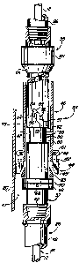
Figure 7 is a broken, side elevational, longitudinal,
0 pert cross-sectional view of apparatus made in accordance with
another embodiment of the present invention.
5
~t~~~ ~4'~
DETAILED DESCRIPTION OF THE PREFERRED EMBODIMENT
Figure 1 o:E the drawings disclose a production unit by
which a well is produced. A pumpjack unit 10 having a horse head
and bridle for reciprocating a polish rod 12' is shown. The pol-
y ish rod sealingly extends through a stuffing box 14 located on the
Christmas tree 15 and into a wellhead 16 attached to the upper end
of the usual surface casing 18. Numeral 20 indicates the well cas
ing string that is :Located therewithin and extends downhole to
form a cased boreholES. Produced fluid flows away from the well
bore through lateral pipe :19.
A tubing rotator 22, the details of which are more fully
disclosed later on herein and in my co-pending patent application,
is fastened to the wellhead by adaptor 17 and is connected to a
fluid conveying swivel means 24 at a location interposed between
stuffing box 14 and tubing rotator 22 so that the tubing string 26
can convey fluid the:rethrough and rotate respective to the well-
head 16, casing 20, and stuffing box 14. Actuator pull line 28 is
attached to the free end of a ratchet arm 30 and is successively
pulled by each oscillation of the rocking beam at 31 (only par-
tially shown) and thereby successively ratchets and rotates a
shaft 32 by oscillating the ratchet arm 30 in response to each
oscillation of the horse-head and ~,ralking beam of the pumpjack
unit 10. The tubing rotator 22 is connected to rotate a hanger
mandrel 33 by which t:he upper end of the tubing string 26 is sup-
ported from the wellhead and can be placed in tension while it is
concurrently rotated by the hanger mandrel 33. The details of the
hanger mandrel 33 and the tubing rotator 22 is more fully set
forth in my co-pending pate=nt application.
A downhole anchor device 34, sometime referred to as an
anchor tubing catcher, and made in accordance with the present
invention, has a fluid conveying rotatable anchor mandrel 35 (see
Figures 3 and 4) extE;nding from opposed ends thereof. Upper end
36 of the anchor mandrel 35 is connected to production tubing
string 26 and forms part of the tubing string. The tubing string
6
~~~~~4'~
26 forms casing annulus 38 respective to the casing 20. A lower
e:nd 40 of the mandrel 35 is affixed to the upper end of the lower
part 42 of the tubing string. The anchor device 34 includes slip
a~ssembl_y 44 having individual slips 45 mounted for radial movement
respective to a barrel 46 and radially extend from the central
l~~ngitudinal_ axis of the anchor device 34 for engagement with the
interior wall surface of casing 20. The lower end 40 of the anch-
or mandrel 35 of the anchor- device 34 is attached to an upper end
of a lower length 42 of production tubing string 26 within which a
0 downhole pump P (not shown) resides. Other downhole tools, such
a;s gas anchors, seating nipples, and the like, may be included
below the anchor device 34, as may be desired. These other down-
hole tools are known to those skilled in the art.
Figure 2 i7_:Lustrates the rod string 12 extending through
5 the rotatable, tensioned production tubing 26 and forming an ir
regular annulus 47 therewith. Therefore the well of the Figure 2
i;~ a crooked borehole. The mandrel 35 of Figures 1 and 3 has an
interior diameter that is approximately equal to the inside diame
ter of the tubing str:ing so that anything that can be lowered down
'0 through the production tubing string can also be extended through
the anchor device of the present invention. This avoids costly
fishing jobs.
Figure 3, together with other figures of the drawings,
broadly illustrates, in a diagrammatical manner, the relationship
'5 between the various parts of the anchor device and particularly
discloses a locking ~~evice having a J-pin captured within a J-
s_Lot, the details of which will be more fully discussed later on
in this disclosure.
The slip assembly 44 of Figures 3, 6, and 7 include ra
~0 d:ially active, circumferentially spaced slips 45 mounted there
with; and, each having an enlargement 48 biased by spring 51 radi
a_Lly outward into engagement with the casing wall. The enlargement
4f3 acts as a drag device for reasons that will be more fully ap
preciated later on as this disclosure is more fully digested. A
s5 mE~dial body portion of each slip 45 is pivotally received by a
7
~Q9~6~~
b~~ss 49 formed at opposed ends of the anchor barrel 46. A medial
part of mandrel 35 i;~ received within the barrel, and the medial
part is provided with a circumferentially extending groove 50 that
is in communication with a J-slot 52. The J-slot 52 upwardly ex
tends from groove 50.
As seen in Figure 3, the J-slot 52 commences at vertical
entrance 53 and terminates at vertical blind end part 54. Vertical
part 56 is parallel to parts 53 and 54, with the upper ends of
parts 54 and 56 being interconnected by sloped part 55. Shoulder
0 57 of the J-slot ser~Jes to catch the J-pin 58 should the tubing
string somehow inadvertently release and drop downhole while rota-
ting. Groove 50 circ:umfere~tially extends 360 degrees about the
mandrel and terminates at spaced apart shoulders 60 and 62, except
f~~r the J-slot 52, as noted.
~5 In Figure 3, bearing 70 has an inner part that is slid-
aibly received about the mandrel 35, and further includes an upper
surface that abuts lower face of movable annular cone 65. Annular
flange 66 is attached to the mandrel 35 by a plurality of shear
pins 68 which are radially arranged and fix the flange 66 to the
'0 mandrel. The shear pins 68 are designed to shear and fail at a
value in excess of the anticipated desired tension forces applied
t~~ the tubing string by means of the anchor device 34 located at
t:he lower end of the tubing string and the tubing hanger located
within the rotator 2~: at the upper end of the tubing string {see
'5 Figure 1).
When the J-pin 58 is located at the upper extremity of
J~-slot part 54, the anchor device is in the "running in" position.
I:n this position, clockwise rotation of the tubing string while
lifting the tubing siring will unlatch the J-pin 58 from the J-
30 slot 52. When the mandrel 35 is lifted up the borehole, the J-pin
5~~ moves from 54 to position 54', whereupon the mandrel is locked
to the barrel 46, and when the mandrel is rotated, the barrel
rotates therewith. This action is advantageously used to set the
s:Lip assembly 44 in e~ number of known manners in addition to the
35 details set forth herein.
8
Figure 3 shows that the mandrel has been set down and
turned clockwise before being lifted in order to release the J-pin
from the J-pin slot a:nd thereby positioned the pin within the wide
groove 50, as shown. The J-pin 58 is moved from the running in
position 54 into the illustrated position of Figure 3, which is
the rotatable opr~rative position, by lifting the mandrel while it
is rotated clockwise by rotating the tubing string. The pin 58
will travel from 54, down parts 55, 56, through entrance 53 and
into groove 50 where the J-pin is free of the J-slot and thereby
0 allows the mandrel to be freely rotated respective to the barrel
until it is again manipulated back into the part 54' of the J-slot
52. Slips 45 can beg provided at either or both of the opposed
ends of the barrel.
In the embcdiment: of Figure 7, a plurality of bows have
5 the opposed ends 71, 72 thereof attached to the exterior of barrel
46. The bows provide a drag device and are well known to those
skilled in the art. ~3arrel 46 has a plurality of windows 73 form
e~d therein for recei~~ing radially active slips 45 therein. The
outer face of the slips 45, 45' are provided with the illustrated
'0 casing engaging teeth that arrest uphole and downhole movement of
the anchor device when extended into engagement with the interior
of the casing.
The slip assembly 44 has upper and lower wedge faces 74
and 75 that are formed on the inner working surface thereof in op
'5 position to the illustrated casing engaging teeth. Cones or
wedges 65, 65' are provided with wedge engaging faces 76, 77 made
complementary to wedge faces 74, 75, to force the slips 45 radi-
ally outward when the wedges 65, 65' are moved axially towards one
another. The lower end 78 of wedge 65' abuts the upper face of
30 bearing 70 while the lower face of the bearing 70 abuts the upper
face of annular shear flange 66. The bearing 70 is slidably rece-
ived on the mandrel :35. 'fhe J-pin 58 is attached to the barrel
a:nd is shown positioned within J-slot 52 at a location above
groove 50 and thereby is positioned to lock the mandrel and barrel
35 together to prevent relative axial rotation therebetween. This is
9
~~~N~4'~
the locked position of operation. This locked position allows
slips 45 of the slip assembly 44, and wedges 65, 65' to be posi-
tioned in a neutral or retracted position so that the anchor can
be run downhole without becoming engaged with the casing sidewall.
The J-pin 58 is moved into groove 50 when the anchor slips are set
and the mandrel rotated respective to the barrel and casing.
In the embodiment of the invention of Figure 6, the ro-
tatable mandrel 35 of the downhole tubing anchor 34 is provided
with a groove 150 that includes a C-slot 152 formed at a medial
l0 position thereof. The C-slot 152 on the mandrel receives the J-
pin 58 therein for re~strain:ing axial movement between the mandrel
and the barrel, thereby retaining the slips retracted when running
into and out of the hole in the before described manner of Figure
3. Opposed wedges E.4, 165, confront one another and are moved
~5 axially into engagement with respect to the spaced slip assemblies
44 and 44' for extending the slips 45, 45' thereof outwardly and
retracting the slips 45, 45' inwardly respective to the barrel
windows 73. Lower s:Lip actuator 170 has the upper conical wedge
165 formed thereon for engaging the complementary wedge faces of
?0 each slip 45', and further includes a circumferentially extending
keeper at boss 49, 49' that bears against the slip assembly and
retains the individual slips 45 thereof biased towards the central
axis of the barrel anal in t:he retracted position.
Bearings 97 of Figure 6 are sandwiched between the upper
?5 race 98 and lower race 98', with lower race 98' abutting against
face 100 of shear flange 166 and upper face of race 98 thereof
abutting against the shoulder that forms the annular pocket 102
located within the lower sl:ip actuator. The lower slip actuator,
together with annular shear flange 166, forms a bearing chamber
30 within which the bearing components elements 97, 98, 98" are re-
ceived. Shear bolts 68 affix annular shear flange 166 to the mand-
rel and rotate therewith. Shearing bolts 68 releases the slips 45
from the wedge 165 to retract the slips 45 radially inwardly from
the casing wall and l~hereby allow retrieval of the entire tubing
35 string along with the downhole pump P.
~~~~~47
In Figure E., C-slot 152 has an upper and lower curved
portion 154 that communicates with the entrance 153 thereinto.
Those skilled in the art can now readily appreciate that mandrel
3'.~, when the J-pin 58 is in the wide groove between shoulders 160
and 162, can be rotated so long as the J-pin is above or below the
C~-slot 152. The J-pir.~ 58 can be aligned with the entrance 153 of
the C-slot 152, wherE~upon J-pin 58 can be rotatably guided into
the C-slot until the pin bottoms out at either end 154 thereof,
whereupon picking up i~he mandrel results in the J-pin being firmly
0 seated within the part 154. In this position, the locking action
o:E the J-latch device: has rendered the mandrel substantially im-
movable respective to the barrel, and the mandrel cannot be manip-
u:Lated for setting tree unset slips 45 of the anchor device until
the J-pin 58 is manipulated by the mandrel out of the C-slot and
5 into the operative position between the spaced shoulders 160 and
162 of Figure 6.
As particularly seen in Figure 3, J-slot 52 has a lower
carved portion that communicates with entrance 53. Those skilled
in the art can now readily ,a;ppreciate that mandrel 35, when the J-
~0 p:in is in the wide groove 50, can be rotated to align the J-pin 58
with entrance 53 of the J-slot 52, whereupon the J-pin 58 can move
and be guided along the slot until the pin bottoms out at the low-
er end 54' of part 54,, whereupon picking up the mandrel results in
tlhe J-pin being seated within the blind end part 54'. In this po-
~5 s.ition, the locking action of the J-latch device has rendered the
m;~ndrel substantially immovable respective to the barrel, and the
m~~ndrel cannot be manipulated for setting the unset slips 45 of
tl'ne anchor device until the J-pin 58 is manipulated by the mandrel
into the operative position seen 'in Figure 3.
~0 In Figure 7 the r~otatable mandrel of the downhole tubing
anchor is provided with a very wide groove 150 that extends from
s.'houlder 160 to shoulder 162 and accommodates a C-slot 152 within
which J-pin 58 is received for running into and out of the hole in
t:he before described manner of Figure 6. Opposed wedges 76, 77
;5 confront one another and move axially into engagement with slip
11
assembly 44 for extending slips 45 thereof outwardly and retract-
ing slips 45 inwardly of the window 73. Lower slip actuator 82 has
the lower wedge 77 formed thereon for engaging complementary wedge
face 75 of each slip 45, and further includes a circumferentially
extending boss 84 th~~t bears against the upper race of bearing 70
to force the slip actuator 82 uphole when the mandrel 35 is urged
uphole to thereby place the lower end of tubing 26 in tension.
The lower race of be~~ring 70 bears against the shear flange 66 at
88. Shear bolts 68 engage the mandrel and force bearings 70
l0 against boss 84 to set the' slips and thereby place tubing 26 in
tension.
Shoulder 8E~, located on the lower part 42 of the tubing
string, is spaced from the annular shear flange 66 to provide am-
ple lost motion when it is desired to shear the pins 68 and there-
~5 by maintain the dissembled parts accumulated near the bottom of
the anchor device. Shearing the pins 68 releases the slips 45 from
the wedge 77 to retract the slip 45 axially inwardly from the cas-
ing wall and thereby retrieve the entire tubing string along with
the downhole pump P.
?0 In operation, the tubing anchor device 34, 134 or 234 is
interposed within the tubing string any desired distance above
pump P, the locking device at 52, 58 is placed in the locked posi-
tion, and the apparai:us is run downhole into the borehole on the
tubing string to a predetermined depth, thereby properly spacing
?5 out the pump and associated apparatus. At this time, the J-pin 58
is in the end 54 of the J-slot 52 so that the upper end of the
tubing string can subsequently be manipulated to extend and set
slip assembly 44 of the anchor device 34 into engagement with the
casing wall.
30 Then the wE~llhead 16, along with the tubing rotator 22
and other illustrates( members, are all assembled in the manner of
Figure 1. Next, the tubing' string is set down, causing mandrel 35
to urge the J-pin into part 55 of the J-slot; whereupon the tubing
is then picked up, u~,ing a weight indicator, to assure that J-pin
12
58 travels along parts 55, 56, 53, and into the circumferentially
extending wide groove 50.
The groove 50 will at first appear to be excessively
wide until it is re~~lized that there must be ample lost motion
between the co-acting- parts to assure that the confronting shoul
ders at 88 and 90 of the bearing assembly 70 of Figure 7, for ex-
ample, carries the tension load of the tubing string rather than
the J-pin 58 abutting the lower circumferential shoulder 160 of
the groove 150. Hence, it is desirable that J-pin 58 comes to
0 rest more or less equally spaced between the shoulders 60 and 62
of the groove 50 in t:he illustrated manner of Figures 3 and 7, for
example, whereby J-pin 58 is free to rotate within groove 50 under
normal production conditions during rotation of the tubing string.
The rotator 22 is connected in the manner of Figure 1 so
5 that oscillation of the rocking beam of a pumpjack unit moves the
a~~tuator pull line 28 each upstroke of the polish rod and thereby
pulls the line which oscillates ratchet arm 30 which in turn suc
c~essively rotates sh~~ft 32 to thereby rotate the drive mechanism
therefor and to rotate the hanger mandrel 33 which in turn rotates
'0 tubing string 26 all the way from upper swivel means 24 down to
t:he lower end of the pump.
It is possible to successfully use this invention in a
crooked vertical holes with the anchor set at 7,000 ft, for exam-
ple, the tail pipe e~ctending 6300 ft therebelow, and the seating
'5 nipple located at 12,290 ft for a total depth of 13,300 ft.
In a borehole having a crooked upper marginal length of
5, 000 ft, for examplE~, from the bottom of which there extends a
h~~rizontal marginal length of 1200 ft, for example, it is possible
t~~ successfully use i~his invention with the anchor being set at
i0 t:he bottom of the vertical 5,000 foot part of the borehole and the
t~~il pipe extending t;herebelow and into the horizontal 1200 foot
m,~rginal length thereof, whereby the anchor rotates the tail pipe
located in the horizontal section of the borehole.
13