Note: Descriptions are shown in the official language in which they were submitted.
~468-~6
2 ~
PRESSURI~ED AIR/WATER ROCRET LAUNCHEFl AND ROCKET
~ACKGROUND OF_THE XNVENTION ;~
1. Field of the Invention
The present invention is directed to a
liquid jet propelled rocket launcher and rocket.
More specifically, it is directed to a toy which
propels a rocket in a generally upward direction
by a liquid-air propulsion combination. Further,
the present invention utilizes a rocket with a
liquld reservoir, a pump and a pressurized base
vessel whereby pressurized air is pumped into the
rocket reservoir and into the base vessel, and
the rocket is subsequently released for
propulsion~ Thus, the present inventlon pertains
in general ~o motive type rockets which are
launched by hand operation and no chemicals,
.
-. ::,. :
r3
motors, batteries or other power is required.
2. Prior Art Statement
Toys involving launchers have been around
~or at least thirty or fo.rty years and apparently
em~rged with modern rocketryJ although not all
such toys pertain directly to rockets. Over the
years various types of jet-powered toys havP been
developed which rely upon pressurized liquid
within a container in the projectile or
transporter and/or rely upon pneumatic launching.
United States Patent No, 2,733,69g issued to
B. Krinsky describes a rocket toy using a
pressurized launcher and a spring mechanism for
initial thrust. Pressurized air is created by a
hand pump and a resilient washer (42) is u~ed to
retard launching until adequaLe pressure i5
-3-
achieved.
United States Patent NoO 2,927,398 issued to
Kaye et al describes a multi~tage ~ocke~ in
which fluid within chambers in each of multiple
stages of a rocket are pressurized and
sequentially released. Similarly, United States
Patent No. 3,962,818 issuPd to Reginald Pippin
describes a multi-stage rocket with mechanisms
for pressurizing liquid within containers for
each stage.
United States Patent No. ~,~40,896 to M~rvin
Glass et al describes a jet-powered vehicle
wherein a wheeled vehicle has a chamber or
co~tainer within it and has a launching device
which includes an air pump with a one-way valve.
There is also clamp means for holding the vehicle
- - , - . , . , ~.
, .
. . . :
4 b~7L~.~
in the charging pos.ition and a trigger means for
releasing the clamping devic~ following the
charging of the chamber to pe:rmit the vehicle to
be propelled by means of reaction of the jet
driveO
United States Patent No. 4,223,472 describes
a toy missle launching device which utili.zes
pressurized air. It involves a complex system
which includes a large launching guide pipe, a
complex mechanical release mechanism and a three
position valve member for a complex pumping ~nd
launching.
Vnited States Patent No. 4,411,249 issued to
Bonnie Fogarty et al describes a toy ~lider with
a pn~umatic launch~r. In this device, a wristlet
includes a pumping mechanism a~ well as a
_5~ $
flexible conduit to which a glider may be
attached. The pump is used to pressurize and
pneumatically project the gliderO
United States ~atent No. 4,8g7 t 065 issued to
John Fertig describes a toy vehicle and hand held
pneumatic launcher wherein the pumping mechanism
has a piston and hollow cylinder designed for a
particular type of grip of a child coupled with
thumb or hand operation cf the pump mechanism.
United States Patent No. 5,032,100 issued to
Adolf Goldfarb describes a toy vehicle and
launcher which uæes contractive power of liquid
in a liquid expanded chamber to propel the
vehicle. Here, a significantly large reservoir
i6 utili~ed to fill and expand ~ bladder which is
connected to and part of a transporter or toy
: . .
.
r~
-6- ~ ~ v ~ 7 -~ ~
vehicle. It is the expanded, pressurized bladder
with the air and water mixture which propel~ the
vehicle as a result of the contract~on of the
bladder upon release of the vehicle.
Notwithstanding the prior art in this field,
no patent teaches or renders obvious the present
invention device which utilizes a pressurized
launcher with a rocket which has a reservoir
which holds a predetermined amount of liquid.
The reservoir i~ also pressurized so as to create
a predet~rmined volume mixture of liquid and air
to maximize a two step liquid jet propulsion of
the rocket upon launching.
SUMMARY OF THE INVENTION
The present invention involves a liquid jet
propelled rocket and rocket launcher. The
""" ; ~
--7-- .
7 '~ ~ :
launcher has a housing which includes a vessel
for holding pressurized air th~exein, an inlet to
the vessel and an ou-tlet from the v~ssel. Also,
the housing has a jet tube receiver ~xtending
from the outlet and adapted to connect with a jet
tube of a rocket assembly. A pump is connected
to the ve~sel in~et of the housing, the pump is
connected for and capable of pumping air into the
vessel at a pressure sufficient to launch the
rocket assembly. A one way valve is connected to
the pump and permits the flow of air only ~rom
the pump to the vessel. There is a rocket
assembly latch mechanism located on the housing
with means for releasing the latch. There are
also, a rocket assembly which includes a liquid
reservoir for receiving liquid and subsequently
.
., , . : .
~ 2 ~ 3
receiving air under pressure from the pump, a jet
tube extending from the liquid reser~oir and
adapted to sealably and releasably ~onne~t to
said jet tube receiver of the housing.
The rocket assembly with the jet tube is
releasably attachable to the housing with the jet
tube coupled in fluid communication wi.th the jet
tube receiver by the latch mechanism, wherein the
liquid may be stored within the rocket reservoir,
and air may be pumped into the rocket reservoir
and into the launcher vessel by means of
actuating the pump. In addition, a substantial
positive air pressure may be created within the
rocket reservoir and within the vessel, after
which the rocket assembly may be released by the
release means and may ad~ance away from the
' ' ~ I ' . . , ` . . ' ., ' !, ' . ',
~ ~ ~ 2 t~
hou~ing by the pressurized air in the vessel and
by jet propulsion of the liquid and air contained
within the rocket reservoir. :Ln preferred
embodiments the water to air r~ltio and the air
pressure itself are such that the rocket as~embly
is launched in two different discrete phases, one
being a positive air pressure thrust by the
pressurized vessel and the other being a
combination of air and liquid such as water to
create a jet stream thrust from the rocket
assembly.
BRIEF DESCRIPTION OF T~E DRAWINGS
The present invention as described herein
will be more fully und2rstood and appre~iated
when taken in conjunction with the drawings
appended hereto those drawings are as follows:
. ~ ~ '.t ' ~ ~ ~
: . :
,:.
' ' ~
" ' ; . .
- :~ . . ,
--10--
2 ~
Figures l(a), l(b) and l(c) show front
ele~ation views, partially in vertical cross-
section, of a present invention toy, including a
pump, a launcher and a liquid jet propelled
~ocket assembly;
Figure 2 is a partial side elevation view,
partially in vertical cross-section, of a present
invention launcher base; and
Figu.re 3 shows a partial sectional ~iew of a
portion of the launcher shown in Figures la, lc
: and 2.
DETAIhED DE:SCRIPTION OF_THE INVENTION
The present invention toy has been de~eloped
to create a rocket assembly which is jet
.
15 : propelled and which may be launched by hand
preferably utilizing a mixture of li~uid
7 ~
(typically water~ and air, e.q. a predetermined
ratio, in a rocket asse~bly re!servoir and
enabling the user to e~fectively ac~omplish this
in a manner which utilizes an air pressure built
up in both a rocket ssembly and a launcher,
followed by jet propulsion caused by pressurized
air with water exiting from the rocket assembly
for thrust~ Uniquely, the present invention toy
includes a launcher which has a housing with a
pressuriæeable vessel, as well as a reservoir on
the rocket assembly for additional
'
prsssurization. The rocket reservoi.r has a
volume for a predetermined amount of liquid, with
space left for air and subsequent pressurization~
Thus, it is an object of the present
invention to provide an advanced toy for
,, , , ~-
. .
: '., : ~ :: ' '
: . : . :
.
launching rocket assemb:lieR and similar
substantially vertically launched aerodynamic
projectiles and any other form of substantially
vertically launched transporters, which can be
imagined or may yet to be developed in an
exciting and efficient manner. (Thus the words
"rocket" and "rocket assembly~' should be taken to
mean substantially vertically launched
aerodynamic projectiles or transporters.~
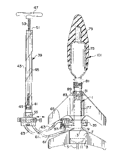
Referring now to Figures l(a), l(b), l(c)
and 2, there is shown in Figures l(aj and l(b)
front elevati.on views r partially in vertical
cross-section, of a present invention toy 1,
including a launcher 11, rocket assembly lOl and
pump 39. FiguFe l(b) shows an enlargement of a
portion of the launcher and rocket assembly and
,: , :,. ": . . : :, :. . -
: ~ . -: ~ . ., . , - ,
- - ~
-13-
~27'1 '~
Pi~ure l(c) shows an enlargement of the pump
system. In Figure 2 is shown a p~rtial side
elevation view, partially in vertic~l cross-
section, of a present invention launcher base
(without showing supports such as support~ 5).
Launcher 11 includes launcher housing 3 which has
a plurality (e.g. three) base supports such as
base supports 5 for support and s-tability as well
as a housing vessel 7. Vessel 7 includes a
vessel inlet 9 which includes attachment ste~ 13
shown in Figure 2. Also shown in Figure 2 is one
way check valve 12 which allows aix to flow into
vessel 7 but, when vessel 7 is pressurized,
prevents air from exiting ves~el 7 through inlet
Facing upwardly from housing 3 is ve~sel
' '
:: . :: : . :
.: . : -
: .. .: . .,
- ~ ::
-14- 2~ ~ 2 7 ~
outlet 15 connected directly to jet tube receiver
27. As will be discussed below, the jet tube
receiver 27 receives jet tube 77 of rockat
assernbly 101. Jet tube receivler 27 includes an
outlet 2S, as shown. Additionally, jet tube
receiver 27 is itself an annulus or tubing or
piping configuration and has a one way valve 31
which opens only to upward flow (e.g~ air)
through orifica 33.
The housing 3 al~o includes a rocke~
asse~bly latch mechanism 17 which is bia5ed by
spring 19 to latch over l.ip 21. Release means 23
is slidably moveab:Le left to right and vice versa
~-
: as shown in Figures l(a3 a~d l(c). Release means
23 may be pushed against end 29 of latch
mechanism 17 to relea6e an otherwise latched
~,
'
-15~
rocket assembly for launching (discussecl further
below). Sa~ety features such as encasement ~5
prevent or deter premature or accidental
launchiny by securing release mechanism 17 from
accidental contact.
Also, shown in Figure l(c) is pump 39 with
pump piston support 42 which includes a piston
chamber 43 and a piston rod 45 and a piston 41.
Piston pump handle 47 extends b~yond the outer
end of piston rod 45 and may be reciprocated so
as to pump air into the ve6sel 7 through one way
O-ring valve 49 locaked around piston 41 and
connected thereto, as shown. Piston housing cap
51 supports piston rod 45 and handle 47.
Optional spring 53 acts as a shock absorber
between handle 47 and cap 51 durin~ pumping.
.. ,, ; . . : : . .
,, . : .. ,, ....
-16-
2~J2~
Air is taken into piston chamber 43 at the
opening around piston rod 45 at cap 51. This
occurs when piston pump handle 47 is pulled
outwardly and O-ring valve 49 moves away ~rom the
sealing position and allows air to pass by piston
41 such that air fills piston chamber 43. When
piston pump handle 47 is pushed inwardly, the air
within the piston housing is forced by one way 0-
ring valve 49 past one way valve 55, through
:
cavity 57 located in support 42 through outlet
59, down flexible tubing 61 and into vessel inlet
attachment stem 13, into vessel inlet 9 and into
vessel 7. The air also travel~ up jet tube
receiver 27 and into rocket propulsion reservoir
75 of rock~ assembly 101. Further pumping
increases the air pressure in the vessel 7 and in
, I , , ,
~ ~ ~r`~ r~
the reservoir 75 of the rocket assembly for
subsequent propulsion. ~oweve:c, if a
predetermined maximum acceptab:Le pressure is
reached, pressure release valve 60 prevents
further pressure build up.
Release means 23 is, as mentioned, ~liclably
mounted so that it may be pushed into end 29 of
latch mechanism 17. When jet tube 77 of the
rocket assembly 101 is inserted onto jet tube
receiver 27, it may be secured in place via latch
mechanism 17. When the rocket propulsion
reservoir 75 has water and the rocket propulsion
reservoir of rocket ~ssembly 101 and vessel 7 of
launcher 11 are fully pumped up, e.g. with 60,
70, 80 or higher p.s.i., the user could press a
xelease mechanism to launch. But here, a safety
-18- 2~27~.r~
advantage is achieved because release means 23 is
activated remotely. Flexible tubing 63 conne~ts
a second outlet 65 from pump piston support 42 to
release inlet 67 of launcher 11.
When spool valve 69 (or its equivalent ~ is
shifted from right to left, air pressurizes
tubing 63 instead of tubing 61 and pushes on
release means 23 to release latch mechanism 29.
This causes rocket assembly 101 to launch and ~e
propelled, first by the air pressure in the
launcher vessel 7 and the rocket assembIy 101,
and then by subsequent pressure release Erom
inside jet tube 77 and rocket propulsion
reservoir 75. The initial air pressure from the
launcher may be only ~or a fraction of a second
: or so while the released pressure and water jet
-19- 2~9~7'~
stream from the jet tube 77 and reservoir 75 may
last for a number of seconds, e.g. 10 or 20
seconds or more.
Rocket assembly 101 includes jet tube 77
with constricted jet orifice 73, and threads 71,
for receiving reservoir 75. In this case there
is a foam cover for rocket propulsion reservoir
75, as shown. Reservoir 75 includes threads 81
at orifice 95 for connection to jet tube threads
71. Rocket assembly 101 is in the form o~ a
simulated vehicle, in thia case a rocket with
fins such as fin 83 and brackets such as bracket
89. The fins such as fin 83 may be remo~able, as
here. ~hile attachment of the reservoir 75 is by
threading, the thr~ads are not essential and a
snap on, clamped or sealed arrangement would work
:: - . : :~ :- .: :.
2 ~
sufficiently. Propulsion reservoir orifice 9S
attaches to constricted jet orifice 73 with a
t.ight seal via washer 97
A user fills reservoir 75 with water to 50~,
60~, or so, of capacity while inverted (orifice
95 upward), and screws it onto jet tube 77. The
thus assembled rocket assembly 101 is then
in~erted and placed on jet tube receiver 27. The
assembly 101 is then snapped into a latche~
position and releasably latched by latch
mechanism 17. Air is pumped via pump 39 into the
launcher vessel 7, the jet tube receiver 27 and
the roc~et propulsion reservoir 75 and through
the various connecting means. Valve 31 prevents
water from emptying into vessel 7 from reservoir
75. When the pump has been actuated a
-21- 2~
predetermined number o~ counts, e.g., twenty, the
toy 1 is ready for launching.
The user next switches spool valve 69 by
pressing or pulling it to the opposite position
from that shown in Figure l(B3. By so doing, the
user closes off outlet 59 and opens outl~t 65.
Further pumping increases air pressing in tubing
63 and this continues to increase until adequate
pressure i5 achieved to overcome the force of
spring 19, thereby pushing latch mechanism 1/ to
the open position and launching rocket assembly
101 as previously described. This pump releasing
means adds significant play value to the toy, as
it simulates the plunger activated detonation of
explosives as requently depicted in animations~
Significant safety advantages are achie~ed
~ .
~. ;; ' "''',, ' '
-22-
by the embodiment o the prese-nt invention shown
in Figures 1 and 2. As mentioned, encasement 35
prevents direct release o~ latch mechanism 17 and
encourages remots release via pump 39. Further,
the "soft" rocket assembly 101, comprising
reservoir 75 covered with a foam nose cone 79,
limits any injury which could occur from
accidental impact to a user ar other person or
property in the are~. Further, a "tilt switch"
97 which would prevent release of the rocket
unless it were kept in a substantially vertical
position. This includes a ball ~alve 99 at
outlet 1030 If toy 1 is tilted to an angle o~
greater than, say about 15 from the vertical or
aimed at someone, or falls over, bal] valve 99
will unseat and pressure pumped into tubing 63
-23-
will exit through outlet 103 and the user will be
una~le to release latch mechanism 17. While this
is an optional feature, it will prevent the use
of the toy for firing at other people.
Figure 3 shows a partial sectional view of a
portion along line 3-3 of Figure 1 of launcher 11
with the upper part of encasement 35 removed.
Parts identical to those shown in Figure 1 are
identicall~ numbered~ Guides R5 and 87 support
latch mechanism 17 allowing it to be moved from
left to right and vice versa, although it is
biased to the left in its resting and latching
position via spring 19. Similarly, release means
23 is reciprocally movable within mounting
flanges 91 and 93.
The construction of the pr~ent in~ention
2 4~ ~ ;, r~
toy is, typically, oE various types of plastic
and, once the invention is appreciated, the
selection of soft and hard plastics.for various
components will be within the skill of the
artisan. For example, high density polyethylene
may be used for certain aspects whereas other
plastics may be utilized, for example, tubing
could be typical vinyl tubing and the ~ittings
could be hard rubber fittings or otherwise.
~dditionally, some or all parts may be made of
other material~ such as materials typically
a~ailable in the construction of toys, including
rigid and flexible foams, metals, graphite, etc.
Obviously, numerous modifications and
lS variations of the present invention are possible
in light of the above teachings. It is th~refore
-25- 2 ~S;~ 2 ~ .3
understood that within the scope of the appended
claims, the invention may be practiced otherwise
than as specifically described herein.
~ ~ :; ,, ,; , ," , , ~