Note: Descriptions are shown in the official language in which they were submitted.
wo ~U06~ 2 0 ~ 3 012 PCT/AU91~00169
This in~ention relates to apparatus for the controlled
supply of alumina or other solid materials to an
S electrolytic tank in whicA the alumina is converted to
aluminium.
In the electrolysis of alumina, solid alumina is
dissolved in a tank or pot containing molten electrolyte
such as cryolite and it is desirable to maintain the alumina
concentration in the electrolyte within a predetermined
range. In current practice for the electrolysis of alumina,
the alumina is fed in successive doses of predetermined size
into one or more holes which are made in the electrolyte
crust so that the alumina can be adm~tted when re~uired. As
the electrolysis of the alumi~a proceeds continuously, it
would be desirable if the alumina consumed in the
electrolysis proce~s could be continuously replaced so as to
mainta~n the optim~m alumina concentration in the
electrolyte. However, the optimum operating conditions are
such that the electrolyte crust continuously reforms on the
surface of the electrolyte making it difficult to
continuously supply alumina to the molten electrolyte
beneath the crust. For this reason, ~nown alumina feedin~
procedures involve the use of a crust breaker which is
operated intermittently to break the electrolyte crust and
form a hole through which the solid alumina can be fed.
However, the action of the crust breaker is necessarily such
that the crust breaking mechanism, such as a pneumatically
operated shaft with an appropriate chisel means (hereinafter
SUB5TITUTE Stl~T
- - .
i.`., ~ - . . - . ~ : . -
'' :. ~..... ' :7 --
:: .... - . . .
wo g~z~ 2 ~ ~ 3 012 PCTtAU91/00169
;~ referred to as a plunqer) at its free end, will be moved in
and out of the hole formed by the plunges.
In one known feeding procedure, two separate pneumatic
systems are employed, one operating the crust breaking
; mechanism and the other operating the alumina feeding
system. In this procedure, it is possi~le for the mechanism
operating the crust breaking mechanism to form the necessary
hole in the electrolyte crust and retract the crust breaker
so that the feeding system can then be operated to place a
charge of alumina into the hole formed by the crust breaker.
In another procedure, a single pneumatic system is
used to operate the crust breaking mec~anism, and the
discharge of alumina from a storage device is co-ordinated
with the downward movement of thL crust breaker. In th~s
procedure, the alumina charge is thus released when the
crust breaker is through the crust so that the alumina is
not ree to enter the hole in the crust until the crust
breaker is retracted. While this procedure has the
advantage of a single pneumatic system, it is obvious that
not all the alumina will be able to pass through the hole
into the electrolyte immediately when the crust breaker is
retracted.
It is an object of the present invention to provide an
improved alumina feeder assembly which can utilise a single
pneumatic mechanism ~ut avoid the disadvantages of the known
system using such a single mechanism.
Accoraingly the present invention provides a feeder
assembly for an alumina electrolysis tank including a crust
breaking mechanism operable to break a hole in crust formed
SU8STITUTE SHEET
.
-
- , - ~ .
: . . .
wo 92/06230 2 0 ~ 3 0 ~ 2 Pcr~AV9~ 69
3-
on the surface of molten electrolyte, the orust breaking
mechanism including a plunger with a cutting edge mounted on
a reciprocable plunger shaft, and an alumina storage
container adapted to release alumina as required for entry
into the electrolyte through the hole in the crust,
characterised in that the storage container feeds alumina
through an alumina supply passaqe and an entry port into a
supply chamber defined between an inner wall of the feeder
assembl.y and an outer supply chamber wall: a supply chamber
esit port controlled by a valve means connects the supply
chamber to a dose holder having an inner wall mounted around
and concentrically with the plunqer shaft; the inner wall is
urged downwardly towards the head of the plunger; an entry
port in the dose holder is i~.7ediately adjacent to the
lS supply chamber esit port so that when the valve means opens
the supply chamber eYit port, it simultaneously opens the
dose holder entry port and alumina in the supply chamber is
able to flow directly to the dose holder; the valve means is
operatively associated with the inner wall so as to move in
response to the movement of the inner wall between a ~irst
position in which the dose holder is clo~ed to the supply
chamber and a second position in which the dose holder is
opened to the supply chamber, the valve means being open in
its first position to a flow passage defined between the
inner wall and the valve means and in its second posi~ion
closing off the dose. holder from the flow passage: the dose
holder is a chamber defined by an outer wall, two radially
inwardly directed end walls and a radially inward movable
wall formed by the valve means, the movable wall def inlng
~UBSTnnJr~ S~T
.
: . . :. ~. ' :.
,, . ~ ~. . . ... . . . -. ~. .
W092~Z~ 2 ~ ~ 3 ~12 PCT/AU9l~00169
3 - 4 -
with the respective end walls alternati~ely, depending on
the position of the val~e means, a dose holder e~t port
leading to the f low passaqe or an entry port leading to the
supply chamber, so that wh2n either port is fully closed,
; the other is fully opened; the lower end wall of the dose
holder is downwardly and inwardly inclined towards a valve
seat formed in the lower end wall and defining the lower
part of the dose holder esit port; the valve seat in the
lower end wall provides a stop to terminate the downward
travel and hold the valve means against th~ downward urging
of the associated inner wall while the plunqer shaft may be
driven further downwardly to break the electrolyte crust;
striker me~ns on the plunger shaft which meets the lower
edge of the inner wall as the pl~.nger shaft is raised from
its crust breaking operation and raises the inner wall and
its associated valve means to clo~e the entry port and open
the, e~it port o the dose holder, and an inclined wall
connecte~ adjacent to the lower end of the inner wall of the
~eeder assembly and terminating at its lower free edge at or
within the entry portion of a delivery chute adapted to be
mounted below the feeder assembly and to provide a
funnel-like action to direct alumina which leaves the dose
holder to one or more outlets terminating in u~e above the
hole in the electrolyte crust.
2; The feeder assembly o~ the present in~ention includes
a crust breaking mechanism ~hich is pref~rably pneumatically
operated. The crust breaking mechanism includes a plunger
with a cutting edge for breaking the crust mounted on a
reciprocable plunger shaft. .~he plunger shaft preferably
SUBSTITUTE SHEET
.. ~ . . .. . .
.. :... ., . - . ~ ~ . -
W09~06~ 2 0 ~ 3 012 PCTIAU91/00169
r- - -5_
carries striker means which may consist of a collar adjacent
the plunger or a shoulder by the junction of the plunger
shaft and the plunger.
The feeder assemb~y further includes at least one
i storage container comprising a hopper or like vessel for
finely divided alumina. Other storage containers may be
associated with the feeder assembly for other additives to
the electrolysis tank such as aluminium fluoride, calcium
fluoride, crushed bath, soda ash, or cryolite. The other
storage containers may be adapted to feed their contents
into the tank in a similar manner to that described below
for the alumina.
A supply chamber provided between the storage
container and a dose holde-r includes a preferably
substantially cylindrical inner wall mounted around and
concentrically with the plunger shaft. The inner wall is
urged downwardly towards the head of the plunger, preferab~y
by spring pressure eserted between a radially outwardly
estending flange on the inner wall and a feeder assembly
outer wall which is also mounted concentrically with the
plunger shaft. The feeder assembly outer wall may include a
radially e~tending flange more remote from the plunger head
than the flange on the inner wall so that a ooil spring
mounted between the respective inner wall and outer wall
2j flanges can esert the desired pressure urging the inner wall
downwardly until its downward movement is terminated, T~e
spring is mounted in the upper portion of the supply chamber
so that alumina in the supply cha~ber will not interSere
with the spring operation.
SUBSTITUT~ S
wo 92t~ 2 ~ 9 3 ~12 PCT~AU91/00~69
f,~"., --~ _
The supply chamber is defined betwe~n the inner wall
of the feeder assembly and a preferably substantially
cylindrical outer supply chamber wall. The supply chamber
includes an entry port connected to an alumina supply
S passage below the inner wall 1ange and an esit port
controlled by a valve means. The capacity of the supply
chamber is preferably at least that of the dose holder. The
inner wall at the supply chamber is preferably supplemented
by a substantially downwardly and outwardly directed supply
chamber side wall which terminates at its lower edge by the
supply chamber e~it port. Preferab~y the supply chamber
side wall is inclined at an angle greater than the angle of
repose of the alumina which is to pass throu~h the supply
chamber. This ensures that the aiumina will flow freely
1; through the chamber.
The supply chamber e~it port is immediately adjacent
to an entry port in the dose holder so th~t when the valve
means opens the esit port o the supply chamber, it
simultaneously opens the entry port to the dose holder, and
2~ alumina in the supply chamber is able to flow directly to
the dos~ holder.
The val~e means is operatively associated with the
inner wall so as to move in response to the ~ovement of the
inner wall between a first position in which the dose holder
is closed to the supply chamher, and a second position in
which the do~e holder is opened to the supply chamber. In
its first position, the valve means is open to a flow
passage defined between the inner wall and the valve means.
In its second position, the ~alve means closes off the dose
SUBSTITUT~ SI~EE~
` .
: . . ..
`.
.: ` '`. ., . ~, ` `~ `
:` : , - : :
. ,` . , ` , . .
wo 92J06~ ~ 2 ~ 3 ~ 0 12 PCT~AU91/00169
holder from the flow passage. The valve means is preferably
substantially cyli~drical and is connected to the inner wall
between its free end edges. Each of the respectiYe free end
edges of the cylindrical valve means is adapted to seat in
; an annular seat defined at the opposite ends of the dose
holder.
The dose holder is a chamber defined by an outer wall
which is preferably substantially cylindrical and has two
radially inwardly directed end walls in which the respective
annular seats are defined, and a radially inward movable
wall formed by the val~e means. Depending on the position
o the valve means, the dose holder will always include an
open port constituting an e~it port leading to the 10w
passage or an entry port leading to a supply chamber. The
nature of the port in the dose holder is controlled by the
movement o the valve means so that when either port is
fully closed, the other is fully open.
Preferably the lower end wall is substantially
downwardly and inwardly inclined at an angle greater than
the angle of repose of the alumina powder which is to be fed
through the dose holder. This inclination of the lower end
wall eni~ures that all the alumina powder (other than that
held in the annular seat) wi11 ~low from the dose holder
when the esit port is open.
The inclination o~ t~e upper end wall is substantially
downwardly and outwardly. The upper end wall is prefera~ly
also inclinea at an angle greater than the anqle of repose
of the alumina powder which is to be fed through the dose
holder. This inclination of the upper wall ensures that the
SUBSlTnUnE 5HEEr
. ; - . . ., . . - -, -.......................... i: ~
. . : ., ~ .; : : . . .: . ~ -
W092/06 W --8 2 ~ 9 ~ ~12 Pcr/Au9~ 69
' ,` ~'1
- dose chamber will b~ filled with alumina, thus providi~g the
desired accurately reproducible dosage.
The annular seat in the lower end wall not only
provides a means of sealing the esit port of the dose
holder. It also pro~ides a stop to termi~ate the downward
travel of the valve means and the associated inner wall
which occurs when the plunger shaft is lowered in response
to the downward urging of the spring or other pressure
essrting means. The valve means is held in the lower end
wall seat by the downward pressure while the plunger shaft
may be driven further downwardly if the crust is to be
broken.
When the plunger shaft is raised, means consisting of
the plunger head itself, or the preferred striker mean$,
meets the lower edge of the inner wall and raises it and the
associated valve means to close the entry port and open the
esit port of the dose holder. The upward movement of the
inner wall i~ terminated when the upp,er end edge of the
valve m~ans seats within the annular seat in the upper wall
of the do~e holder.
The feeder assembly further includes an inclined wa 11
connected adjacsnt to the lower end of the inner wall. The
inclined wall is preferably of substantially frusto-conical
form and terminates at its lower, free edge at or within the
2; entry portion of a delivery chute.
The delivery chute is adapted to bs mounted below the
feeder assembly and is adapted to provide a funnel-like
action to direct alumina which leavQs the dose holder to one
or more outlets which terminate in u~e above the hole in he
SUBSTITUTE SHE~T
.~ ` .` , ~ . .` -
, . ~, - . . - - ,
. ~ " ` ` -
`. . .
. . ~ .
., . ~ . . . . .
wo 9v~ O 9 3 012 PCT/AU91/00169
electrolyte crust. The delivery chute pre~erably directs
all the alumina leaving the lower edqe of the inclined wall
at the base of the inner wall, towards one or more delivery
outlets 5.
To assist a further understanding of the i~vention,
reference is now made to the accompanying d~awing whic~
illustrates one preferred embodiment of the present
invention. It is to be appreciated that this embodiment is
given by way of illustration only and that the invention is
not t~ be limited by this illustration.
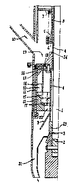
The drawing shows, somewhat diagramatically, one half
only of a sectional view of a preferred form of feede~
assembly. Plunger shaft 1 is connected to plunger 2, and
shoulder 3, which is at the junct;on of plunger shaft 1 and
plunger 2, abuts striker means 23 on inner wall 4 in the
position shown. Inner wall 4 is urged downwardly by spring
5 which is held between flange 6 on inner wall 4 and flange
7 on outer wall 8. Inclined wall 9 at the lower end of
inner wall 4 is connected adjacent to the junction of inner
wall 4 and the striker means 23.
The chamber forming dose holder lO is defined between
side wall 11 and end walls 12 and 13, together with valve
means 14 which comprises the moveable wall connected to
inner wall 4. In the drawin~, valve mea~s 14 is shown with
e~it port 15 of dose holder 10 open, while entry port 16 is
closed. Annular seats 17 and 18 for the respective end
edges of val~e means wall 14 are formed in the respective
end walls 12 and 13.
Supply chamber 19 is ~illed generally below the level
SUE3STITUTE SHEE7
... . . . .
.. . . . . . .
. ... . . . - : ~: , -. ` . ~
. . . :. . - ~ -
W092/06230 2 ~ 9 ~ O 12 Pcr/AU9~ 69
_ ~ C
;i
of flange 6 by alumina entering as indicated by arrow 20
from an alumina storage container. Inclined wall 24
supplements. inner wall 4 ts direct the alumina in chamber l9
to entry port 16. Delivery chute 21 is connected as
i indicated to the outermost wall of the feeder assembly and
is adapted to direct the alumina leaving dose holder lO and
flowing via flow passage 22 and down inclined wall 9 into
the hole in the electrolyte crust which has been formed by
plunger 2. It will be appreciated that it was only
necessary for the valve means to move the distance A for a
charge of alumina to be released from the do~e holder. The
movement required. for the plunger to break through thé~
electrolyte crust is considerably greater than that
represented by distance A.
It will be appreciated that the present invention
allows the design and operation of a feeder system which
utilises only a single pneumatic mechanism co-ordinated with
the supply of alumina to the hole in the electrolyte crust
formed by the crust breaking mechanism and that the alumina
can be fed directly into the hole when the crust breaking
mechanism is retracted rom the hole. Although some alumina
flows directly through the dose holder while the valve means
is betng moved from the position in which the esit port is
open to the position where the entry port is open,
2; substantially all of the alumina released from the dose
holder is able to flow directly into the hole in the
electrolyte crust.
It is a further advantage of the present invention
that the downward movement of the plunger can be limited
SUB5TITUTE SHEET
,. . .-
. ., . . .: . .
2 ~ 9 ~ O 12 Pcr/A~9l/00169
, .....
when it is desired only to acti~ate the valve means so as to
recharqe the dose holder. It is not necessary for the
plunger to travel downwardly to the full e~tent required to
break ~he crust, each time some downward mo~ement is
required to recharge the dose holder. The dose holder may
thus be recharged ,and the plunger retracted to release the
charge of alumina, without the plunger travelling fully
through the electrolyte crust. Hence plunger wear is
consider~bly reduced.
The angles o~ the dose holder end walls are greater
than the angle of repose of alumina, so the alumina charging
procedure is not affected to the same e~tent as in the
present feedinq procedures by variations in the quality of
the alumina supplied which leads to more consistent charge
volume precision. Selection of appropriate dose holder
volume allows frequent feeding of alumina into the
electrolyte bath in charges smaller than current charge
sizes 'thus assisting ' in ~aintaining the alumina
concentration more substantially constant.
SU8STITUTE SHEET
.: .. . . .... , - , . ~. . . . ..