Note: Descriptions are shown in the official language in which they were submitted.
2093096
~~cir ic~t ~o~ 0 f the ~to~t o~
I~e~t io~ for ~oc~ss ~ND S~ID -
~TE~D SY~T~M FOE~ I N E~E~T GA~
G~T :~ ON ~' .
Fio~d o~ t}~e l~re~tic~
Th;s invention refers to a process, as
welL as to a skid-mounted system for high-pressure
inert gas generation, utilized for backsurging and
artificial lift in oil wells through the
utiLization of lean gas from a dieseL engine.
Natural gas has been traditionally
utilized as lift gas for purposes of promoting
crude-oil Lift from the reservoir rock in depleted
welLs tlow reservoir pressure). Natural gas is
injected at a deep point of the tubing as from the
annuLus in the welL through a hole in the column,
in an artificial-Lift process referred to as gas-
~ift. The gasification of the fluids above the
injection point reduces the hydrostatic pressure
which acts onto the reservoir rock, thus alLowing
for the influx of crude oil from the rock to the
welL, and from there to the surface.
-
~ ~ 9 3 0 9 ~
'
ALternatively, the gas can be injected through a
continuous thin tube ( f~ex;tube), run into the
column down to the desired depth, in a process
referred to as jet-l if t.
In another example of application, the
ga's is utilized to remove the so-called kiLLing
fluids, saline solutions of controLled density,
utilized to hold the petroleum pressures of the
reservoir rock during the drilling and completion
operations (instaLLation of tubing, valves or
other welL-controL equipment). In this case, at
the end of the operat;ons, the kilLing fluid is
removed by the injection of gas through either the
annulus or the flexitube, in a process referred to
2S backsurging
In addition to natural gas, nitrogen has
been traditionaLLy uti-ized in backsurging
operations, due to its inertness from the point of
vieu of steeL corrosion and oil combustion.
Nitrogen is transported in the Liquid state in
cryogenic tanks, being pressurized and gasified in
mobile un;ts, assembled in-situ, cLose to the
weLL Its main disadvantage lies in the high
. . . ~ . . ~ . . ~
)
~ 0 9 3 0 9 6
cost of procuring it and of its transportation, which
limits its application to short-duration operations.
,
Within the technique of inert-gas
generation for utiLization in petroleum
production, the publication G~ 2~7~9
discLoses a nitrogen-production process for
in~ection in the reservoir rock (~ced
Keco~e~y)~ which encloses the following stages:
- burning of a fueL gas with air in a
combustion chamber of a gas turbine,
thus forming a gaseous mixture of
nitrogen, oxygen and other combust;on
products, in wh;ch the concentration
of oxygen is lower than 20% by volume;
- temperature reduction and compression
of the gaseous mixture thus obtained;
- separation of nitrogen from the
compressed mixture by means of reverse
osmosis in semi-permeable membranes;
and
~ . ,
2093096
- injection of the gas obtained through
a second well (inject;on well).
In-situ nitrogen generation has been
proposed as well. This option, however, presents
as disadvantages the maximum operat;on pressure of
nearly 2,000 ps; (138 atm), the maximum flow rate
of nearly 280 cu.ft./m;n (476 m3/h), the min;mum
oxygen content of nearly 5% for this flow rate,
and the excess;ve weight of the requ;red
equipment.
Moreover, in both the process of the
above-mentioned publication and of in-situ
generation, it is necessary to utilize semi-
permeable membranes for nitrogen separation, but
such membranes present as a great disadvantage the
fact of being fragile to transportation impacts,
being more adequate to Large, fixed instalLations
The problems of the above-described
techniques are solved with the present invention,
the objective of which is to utilize, for
backsurging or artificial-lift in oil wells, flue
~ 2 0 9 ~ O 9 6
gas from a diesel engine, thus eliminating the
costs of (iquid-nitrogen obtainment and
transportation, reducing a(so the physica( space
occupied by the equipment on board, through the
elimination of storage tanks, or gaseous
separation plants, with the additional advantage
of dispensing with the utilization of semi-
permeable membranes for the separation of the
required gas from the gaseous mixture.
~ ~y ~F t~e ~ rer~t io~
Pursuant to this ;nvention, a process is
provided for generation of an inert gas uti~ized
for backsurging in oil we((s, in which the f(ue
gas, after the discharge of the diese( engine, is
initia((y coo(ed and submitted to a stage of
separation of water and eventua( solid particLes
(cyc(one), being thereafter admitted to the
(reciprocating) compressors (amounting to 4
stages), in which it isco-~pl~sseduptothe
working pressure (2,500 psi - nearly 172 atm~,
beinq then coo(ed down to the working temperature
(100~F - near(y 38~C), and being then avai(ab(e
for uti(ization.
;~
d
- 6 - ~ Q 9 3~ 9 6
Another objective of this invention is to
provide a system for inert gas generation, which
includes a diesel engine for flue-gas discharge from the
turbine of the turbocompressor, cooling means for flue-
gas temperature reduction, separating means for water
and eventual solid particles from the flue gas, and
means for compressing the flue gas, said diesel engine
providing the whole energy required for the compression
and cooling stage, which is hydraulically transmitted to
the various elements in the system.
The present invention, then, in one aspect,
resides in a process for the generation of inert
gas, utilized for backsurging and artificial lift in oil
wells, characterized in that it comprises the following
stages:
a) admission of atmospheric air into a
diesel engine through an air filter and
turbocompressor of the diesel engine;
b) discharge of flue gas from the turbine of
said turbocompressor of said engine,
being initially cooled in a first cooler
and thereafter subjected to a separation
~ ~ a 9 3 0 9 6
- 6a -
of water and any solid particles in a
first cyclone;
. c) admission of the discharge of said first
cyclone with inert gas in a first
compressor, the discharge from the first
stage of said first compressor being
admitted into a second cooler, being
discharged and admitted into the second
stage of said first compressor, being
thereafter discharged and admitted into
a third cooler, wherefrom it is admitted
into a second cyclone;
d) admission of the discharge from said
second cyclone with inert gas into a
second compressor, the discharge from the
first stage of said second compressor
(third stage of the system) being
admitted into a fourth cooler, being
discharged and admitted into the second
stage of said second compressor (fourth
stage of the system), being thereafter
discharged and admitted into a fifth
cooler; and
~'
~ 2 ~ ~ 30 9 6
- 6b -
e) discharge of the flue gas.
The present invention, in another aspect,
resides in apparatus for generation of an inert gas for
backsurging and artificial lift for oil wells, said
apparatus comprising:
a diesel engine;
means for admitting atmospheric air into said
diesel engine through an air filter and a
turbocompressor;
said turbocompressor including a turbine,
means for discharging flue gas from the engine through
said turbine of said turbocompressor, a first cooler for
cooling said flue gas;
a first cyclone, means for supplying said flue
gas from the turbine of the turbocompressor to said
first cooler for initially cooling said flue gas and for
supplying said cooled flue gas from the first cooler to
said first cyclone;
a second cooler;
a first compressor having first and second
stages, means for supplying said flue gas from the first
cyclone after separation of water and solid particles
from said flue gas to said first stage of said first
. .
~ ~93Q 9~
- 6c -
compressor and from said first stage into said second
cooler for further cooling said flue gas;
a third cooler, means for supplying said flue
gas from said second cooler to said second stage of said
first compressor for further compressing said cooled
flue gas and for supplying said flue gas from said
second stage of said first compressor to said third
cooler for additionally cooling said flue gas;
a second cyclone, means supplying said flue
gas from said third cooler to said second cyclone
downstream thereof for further separating water and
solid particles from said flue gas after cooling within
said third cooler;
a fourth cooler;
a second compressor having first and second
stages, means for supplying said flue gas from said
second cyclone to said first stage of said second
compressor and for supplying said flue gas from said
first stage of said second compressor to said fourth
cooler;
means for removing said further cooled flue
gas from said fourth cooler and admitting said further
cooled flue gas into said second stage of said second
compressor for further gas pressurization;
... .
~, ~
-
~0~0 96
- ~d -
a fifth cooler, means for supplying said
further pressurized flue gas from said second stage of
said second compressor to said fifth cooler downstream
thereof; and
means for discharging said further cooled flue
gas within said fifth cooler from said fifth cooler
after further cooling of same in a condition where said
flue gas is highly inert and at a high pressure by
compression within said first and second compressors for
lifting crude oil from a on-site oil well.
Brie:E Description of the Drawings
In order that this invention may be more
readily understood, reference will now be made to the
following detailed description, which is given merely by
way of example and with references to the accompanying
drawings, in which:
~'
~ , ~ .
~ 2~93096
-- 7
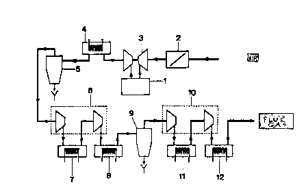
Fi~w~e ~ represents the flow chart of
the inert-gas generation process, according to
this invention;
Fig~c 2 iS a schematic view of the
lay-out and simp~ified hydraulic scheme, which do
not show the coolers, separators, gas lines, water
lines and engine accessories;
Figw~e 3 iS a schematic view of the
gas-cooling water circuit, which does not show the
compressors, separators, gas and hydraulic Lines,
and engine cooling; and
~ i~w~e ~ represents the simplified
flow chart of the petroleum artificial-lift
process, uti~izing fLue gas from a diesel engine,
generated with the process of this invention
Detai ~e:,a Desc~i~t io~ oi~ t}~e
I ~rcr~t ior~
Pursuant to this invention and as it may
be seen in the flow chart of Figure 1, the process
for inert-gas generation utilized for backsurging
~ ~ Q ~ 3~ g 6
and artificial lift in oil wells includes the
fol~owing stages:
a) a(lmi.~.~ion of atmospheric air at a pressure of
nearly 14.7 psi (nearly 1 atm) and at a
temperature of 80~F (nearly 27~C) into diesel
engine 1 through an air filter 2 and a turbo-
compressor 3 of the diesel engine;
b) discharge of the flue gas from the turbine of
the compressor 3 of the engine 1 at a temperature
of nearly 550~F (nearly 188~C), being initially
cooled in a first cooler 4 and thereafter subjected
to a separation of water and any solid particles in
a first cyclone 5;
c) ~(1mi~.sion of the discharge from the first cyclone 5
with inert gas at a pressure of nearly 14.7 psi
(nearly 1 atm) and at a temperature of 120~F (nearly
49~C) into a first compl~sor 6, the discharge of the
1st stage of the first conlpl~ssor 6 at a pressure of
nearly 54.5 psi (nearly 3.8 atm)
A :
2~Q ~
g
and a temperature of 372~F (nearly 189~) being ~(1milted
into a second cooler 7, being discharged and ~rlmitted at
a pressure of nearly 51 psi (nearly 3.5 atm) and at a
temperature of 120~F (nearly 49~C) into the 2nd stage of
the first compressor 6, being thereafter discharged and
atlmitted at a pressure of nearly 169 psi (nearly 13 atm)
and at a temperature of 372~F (nearly 189~C) into a third
cooler B, whelerlolll it is ~mitted into a second cyclone 9;
d) ~(1mi~si~n of the discharge from the second cyclone 9 with
inert gas at a pressure of nearly 185 psi (nearly 12.8 atm)
and at a temperature of 120~F (nearly 49~C) into a second
, . ,
compressor 10, the discharge of the 1st stage of the second
compressor 10 (3rd stage of the system) at a pressure of
nearly 683 psi (nearly 47 atm) and at a temperature of 372~F
(nearly 189~C) being ~(1milted into a fourth cooler 11, being
discharged and ~tlmhted at a pressure of nearly 676 psi
(nearly 47 atm) and at a l~ll,L)el~lule of 120~F (nearly 49~C)
in the 2nd state (4th stage of
A
~ ~ O Q ~0 9 6
- 10 -
the system) of the second compressor 10, being thereafter
discharged and ~lmitt~-l at a ~ ul~ of nearly 2,500 psi
(nearly 172 atm) and at a temperature of 372~F (nearly
189~C) into a fifth cooler 12; and
e) discharge of flue gas at a pressure of nearly 2,490 psi
(nearly 171 atm) and at a temperature of 100~F (nearly
38~C), being available for backsurging in oil wells.
The composition of the atmospheric air
admitted into the diesel engine 1, as is welL-
known by the experts, is of approx~nately79% of N2and
21% of ~2~ and the composition of the f(ue gas
from the diesel engine 1 varies as a function of
the air/fuel ratio (refer to Tab~e 1 be(ow -
LICHTY, L.C. & MAC-COULL, N.: INTERNAL COMBUSTION
ENGINES, in: STANDARD HANDBOOK FOR MECHANICAL
ENGINEERS, Seventh Edition, U.S.A., McGRAW-HILL
BOOK COMPANY, 1967, pp. 9.146). For the reguLar
operating range, the air/fuel ratio varies from 11
(rich mixture) to 17 (lean mixture).
. .
~09309 G
.
1 ~
T ~ B ~ ~
S~ ~y o~ :C.ea~ Ga~ C~ _ ~e~ts
~ir-FueLR~tio Percentage by VoLume
C~2 ~2 CO H2 N2 H2O
11 8.76 0.15 9.14 4.66 77.0813.76
1210.18 0.44 6.65 3.39 79.1313.93
1311.60 0.59 4.31 2.20 81.0914.16
1413.02 0.63 2.09 1.07 82.9914.46
1513.23 1.35 0.99 0.50 83~7214.09
1612.62 2.49 0.68 0.35 83.6513.30
1712.00 3.55 0.48 0.25 83.5112.54
1811.45 4.49 0.30 0.16 83.3911.88
1910.90 5.36 0.20 0.10 83.2311.25
2010.40 6.15 0.11 0.06 83.0710.68
21 9.92 6.86 0.08 0.04 82.9010.16
22 9.44 7.55 0.06 0.03 82.719.65
23 9.00 8.18 0.05 0.03 82.539.19
24 8.60 8.74 0.06 0.03 82.378.78
- 12 - ~ ~ 9 ~
As it can be inferred from TABLE 1, the flue gas
which is discharged from the diesel engine 1 presents, in
percentage by volume, from about 8.76% to about 12.00% of CO2,
from about 0.15% to about 3.55% of ~2~ from about 9.14% to about
0.48% of CO, from about 4.66% to about 0.25% of H2, from about
77.08% to about 83.51% of N2, and from about 13.76% to about
12.54% of H2O. Within these limits, the m~imllm concentration of
~2 in the flue gas is about 3.55%, well below, therefore, the
lower limit of explosiveness for oxygen/hydrocarbon mixtures
(TAE~LE 2 below - BERNARD, L. & VON ELBE, G.:
CO~BUSTION, FLAMES AND EXPLOSIONS OF GASES,
Third Edition, ORLANDO, ACADEMIC PRESS INC., 1987, pp. 709),
always larger than nearly 10% of ~2-
. ~
A '''
~93096
,~
~ T ~ B ~ :~ 2
Pe rcent age of Maximum Oxygen Sa f et y ( PMOS )
F~e:~PMOS* (X by vo lume of ~2)
Methane 12.1
Ethane 11.0
Propane 11.4
Butane and Upper
Hydrocarbons 12.1
Ethylene 10.0
Propylene 11 . 5
Cyclopropane 11.7
Butad;ene 10.4
Benzene 11 . 2
* Ambient temperature and 1 atm.
.
- 14 ~ 3 ~ ~ 6
Another objective of this invention
refers further to the sk;d-mounted system for
high-pressure inert gas generat;on, uh;ch incLudes
a diesel engine 1 for discharge of the flue gas
from the turbine of the turbocompressor 3, cooling
means 4, 7, 8, 11 and 12 for flue-gas temperature
reduction, means 5, 9 for separation of water and
eventual soLid particles from the flue gas, and
means 6, 10 for compression of the flue gas, said
diesel engine 1 supplying the whole energy
required for the compress;on and cooling stage,
wh;ch is hydraulically transmitted to the var;ous
elements ;n the system.
As it can be ;nferred from Figure 2, in
which the lay-out and the simplified hydrauLic
scheme of the system are represented, the diesel
engine 1 provides the flue gas to be compressed
and the power for the driving of all equipment
units, which is hydraulically distributed, so that
two main hydraulic engines 13, 14 drive the gas
compressors 6, 10 of the process, and two
auxiR ary hydraulic engines 15, 16 drive the fans
..,
. ~-~
_ 15 _ ~ 0 9 3 0 9 6
17, 18 and the cooling-~ater pumps 19,20, the
hydraulic pumps 21, 22, connected to the diesel
engine 1, be;ng a~so shown
Thus, as it can be ,inferred from Figure
3, which represents the gas-cooling circuit, the
gas coolers 4, 7, 8, 11 and 12 are cooled by
water, which is impelled by the pumps 19, 20 in
closed circu;t, the water being cooled in the
radiators 23, 24 by means of the fans 17, 18, the
pumps 19, 20 and the fans 17, 18 being driven by
the hydraulic engines 15, 16.
In addition, it must be pointed out that
the total estimated weight for the whole system is
equal to nearly 15 tons, distributed over 3 skids
25, 26 and 27. The greatest advantage of the
proposed skid-mounted system and respective
process is that the diesel eng;ne provides the
whoLe energy required for the compression and
cooling stages, which is hydrauLical~y transmitted
to the various elements in the system, it being
shown, according to pre~iminary calculations, that
the system and process proposed can produce
inert gas at a flow rate of 445 cu~ft /min
~'
. . ~ .
- 16 ~ 3 0 9 6
(nearly 756 m3/h) and at a ~re~ of 2,500 psi (nearly 172 atm).
Furthermore, for the sake of
illustration, Figure 4 shows a simp~ified flow
chart of the gas-lift process, utili~ing flue gas
from a d;ese~-cycle engine generated with the
process and skid-mounted system of the invention,
in which the flue gas from an internal-combustion
engine of diesel cycle 28, with low oxygen
concentration, is compressed at a reciprocating
compressor 29, driven by the diesel engine.
During the process, the gas is cooled in heat
exchangers 30 and purified in separators 31. Due
to the low oxygen content, the compressed fLue gas
may be injected at a deep point of the tubing 32
of an oiL well, promoting the gasification of the
f~uids above the injection points. Said
gasification reduces the hydrostatic pressure
prevailing in the reservoir rock 33, a~owing for
the influx of crude oil from the rock to the we(~,
and therefrom to the surface.
,