Note: Descriptions are shown in the official language in which they were submitted.
2093110
TITLE: NOSE PIECE RETAINER FOR ABRASIVE BELT BACKING SHOE
Thisinvention relates generally to belt-type grinding
machines and refers more particularly to a retainer for the
nose piece of a belt-backing shoe.
R~CKGROUND AND S~MMARY
In a belt-type grinding machine, the shoe which holds
the abrasive belt in contact with a part being ground often has
a replaceable, hardened nose piece. The nose piece is generally
T-shaped having a cross member provided with opposite side
portions and a stem between the side portions. The head has a
stem-receiving recess and outwardly facing locating shoulders
on opposite sides of the recess~ The nose piece is mounted on
the head with the stem in the recess and the side portions of
the cross member overlying the shoulders. In the past, the
nose piece has been fastened to the head by conventional screws
which clamp it against one side of the head rather than down
firmly on the locating shoulders. As a result, the nose piece
may tip slightly, resulting in imperfectly ground parts.
Inaccordance with this invention, releasable retainer
means are provided to secure the nose piece on the head comprising
a pin received in aligned openings in the head and in the stem.
The pin has means for forcing the stem into the recess and
2093110
forcing the side portions of the cross member down squarely and
solidly upon the shoulders.
More specifically, the pin has a flexibly resilient
shank extending through the openings, and the shank is provided
with a lateral offset in the stem opening. The pin is rotatable
to a locking position in which the offset presses inwardly on
the stem opening to force the side portions of the cross her
firmly into bearing engagement with the shoulders. In one
embodiment of the invention, the shank has a laterally bent
portion providing the offset. In another embodiment, the shank
has a projection on one side providing the offset.
One object of the invention is to provide a nose piece
retainer having the foregoing features. Further objects are
to provide a nose piece retainer which is of relatively simple
construction, rugged and durable ~n use, and easy to manufacture
and assemble.
Other objects, features and advantages will become
more apparent as the following description proceeds, especially
when considered with the accompanying drawings.
BRIEF DESCRIPTION OF THE DRAWINGS
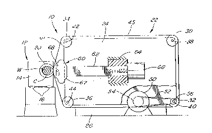
Figure 1 is a semi-diagrammatic side elevational view
of a grinding machine embodying the invention.
--2--
209~
Figure 2 is an enlarged fragmentary side e~evational
view showing the nose piece mounted on the head of the belt-
backing shoe.
Figure 3 is a sectional view taken on the line 3--3
in Figure 2, showing the pin for releasably retaining the nose
piece on the shoe in locking position.
Figure 4 is a sectional view taken on the line 4--4
in Figure 3.
Figure 5 is a side elevational view of the locking pin.
Figure 6 is an end view of the locking pin.
Figure 7 is a side elevational view of a locking pin
of modified construction.
Figure 8 is a view similar to Figure 4, but showing
the nose piece releasably retained on the shoe by the modified
locking pin.
Figure 9 is a fragmentary side elevational view of
the head.
Figure 10 is a fragmentary end view of the head.
Figure 11 is a side elevational view of the nose piece.
Figure 12 is an end view of the nose piece.
Figure 13 is a fragmentary side elevational view in
which the nose piece is shown being held on the head by a prior
art retainer.
Figure 14 is a fragmentary end view of the structure
shown in Figure 13.
209311 ~
DETAILED DESCRIPTION
Referring now more particularly to the drawings and
especially to Figures 1 - 6, the grinding machine 10 has a work
holding unit 12 comprising a table 14 slidably mounted on waybars
16 and movable to an adjusted position by any suitable means
(not shown). The table has a head stock 20 and tail stock (not
shown) for supporting an elongated workpiece W such as a cam
shaft parallel to the direction of table movement. The cam
shaft has a plurality of cams C along its length, one of which
is shown in Figure 1. The cam shaft is rotated by any suitable
power source, such, for example, as a motor in the head stock.
A grinding unit 22 is provided to grind the periphery
of the cam C as the cam shaft rotates. It will be understood
that additional grinding units may be provided so that several
cams may be ground at the same time.
The grinding unit 22 has an upright frame 24 mounted
on a base 26. The frame 24 has two vertically spaced rear belt
pulleys 30 and 32 and two vertically spaced front belt pulleys
34 and 36. These pulleys 30, 32, 34 and 36 are rotatable on
shafts 38, 40, 42 and 44 carried by the frame. A flexible
endless abrasive belt 45 has an abrasive surface on one side and
a backing surface on the opposite side and extends over the
pulleys. The belt extends in a plane perpendicular to the cam
shaft.
2093110
A motor 50 provides the power for driving the abrasive
belt. A timing belt 52 extends over a pulley 54 on the output
shaft of the motor and over a timing belt pulley 56 affixed to
the abrasive belt pulley ~2. Operation of the motor will move
the abrasive belt linearly and it will be understood that the
front generally vertically extending portion 61 of the abrasive
belt will make grinding contact with the cam as the cam shaft
rotates in order to grind the cam to a predetermined contour.
A shoe 60 is provided for each grinding unit to guide
the generally vertical portion 61 of the abrasive belt at the
point where it contacts the cam. This shoe is carried on the
front end of an elongated actuator 62. The rear end of the
actuator is mounted for reciprocation in a housing 64 mounted
on frame 24 and is reciprocated by a motor and ball screw drive
66. The shoe has a head 67 provided with a diamond or ceramaic
nose piece 68 which bears against the back side of the abrasive
belt. The shoe will be described in the position it assumes
in this particular grinding machine, that is, in which the head
67 extends forwardly and the nose piece is on the front of the
head. It will be understood, however, that the shoe may just
as well be disposed in any other position depending on the
particular construction of the grinding machine.
The head 67 of the shoe is in the form of a flat blade
or plate which in this embodiment is disposed vertically so as
to extend in the plane of the abrasive belt which it backs.
209~
notch 7n is cut across the front of the head from one vertical
side wall 72 to the other vertical wall 74. The notch has a
flat front surface 76 and parallel horizontal top and bottom
surfaces 78 and 80 at right angles to the front surface. A
recess or socket 82 in the front surface 76 divides the front
surface into two laterally spaced flat, co-planar vertical
shoulders 84 and 86. The recess is preferably rectangul~r
having vertically spaced parallel end walls extending in
continuation of the surfaces 78 and 80 of the notch 70 and
laterally spaced side walls parallel to the side walls 72 and 74
of the head.
The nose piece 68 is of integral, generally T-shaped
construction, having a cross member 96 and a stem 98. The
length of the cross member is the same as or only slightly less
than the space between the end walls 78 and 80 of the notch and
its width is preferably the same as the width of the head
measured between the side walls 72 and 74.
The stem 98 extends from the rear side of the cross
member. It preferably is the same length as the cross member
but narrower in width so that the cross member has two side
portions 100 and 102. The rear surfaces 104 and 106 of the
side portions are flat and co-planar. The stem is preferably
of the same rectangular configuration as the recess, except
slightly smaller, so that it will fit snuggly in the recess.
20~l~311 ~
When the nose piece is assembled with the head with
its stem extending into the recess, the rear surfaces 104 and
106 of the side portions of the cross member have a flush
engagement with the shoulders 84 and 86 of the head. The
surfaces 104, 106 and shoulders 84, 86 are precision ground so
that when in flush engagement the nose piece is properly oriented
causing the belt to grind the cam exactly to the required
dimensions.
A retainer 110 is provided to mount the nose piece 68
on the head 67 and more specifically to force the stem 98 of
the nose piece down into the recess 82 and to force the side
portions 100 and 102 of the cross member squarely and solidly
against the shoulders so that the undersurfaces 104, 106 of the
side portions 100 and 102 of the cross member are in flush
engagement with the shoulders 84, 86.
The retainer 110 is in the form of a pin which is
disposed in aligned openings in the head and in the stem of the
nose piece. These aligned openings include the spaced holes
112 and 114 formed in the head on opposite sides of the recess
82, and a hole 116 in the stem. ~hen the nose piece 68 is
properly assembled on the head with the stem 68 in the recess
and the side portions 100, 102 of the cross member overlying
the shoulders 84, 86, the holes 112, 114 and 116 line up. The
hole 112 is relatively large and circular. The hole 114 is
smaller and also circular. The hole 116 in the stem is oval-
2 0 ~ 0
shaped, with its major diameter parallel to the lengthwisedimension of the cross member and its minor diameter at right
angles to the major diameter. The holes 112, 114 and 116 have
a common axis. There is a split at 120 in the stem, extending
from the rear end of the stem into the hole 116 along the minor
axis thereof.
The retainer pin 110 has an elongated flexibly
resilient shank 122, an enlarged circular head 124 at one end
of the shank, and a circular collar 126, which is smaller in
diameter than the head 124, at the opposite end of the shank.
The head 124 is only slightly smaller in diameter than hole
112, and has a slot 125 so that the pin may be turned by a
screwdriver or the like. The collar 126 is cylindrical and
only slightly smaller in diameter than the hole 114. When the
pin is fully inserted in the aligned holes as shown, the head
124 is disposed in hole 112 and the collar in hole 114.
The shank is laterally bent intermediate its ends as
shown. The bend in the shank provides a shallow, somewhat U-
shaped offset 130 which is located in the stem hole 116 when
the pin is fully inserted. The offset, upon insertion of the
pin upwardly in Figure 3, will clear the hole 112, and will
also freely enter the hole 116 in the stem provided that the pin
is turned so that the offset is on the major diameter thereof
~see dotted line position in Figure 4). The portions of the
shank on opposite sides of the offset are co-axial. However,
209~
the offset, which is less than one-half the major diameter of
hole 116, is greater than one-half the minor diameter thereof
so that when the pin is rotated 90 the shank 122 must flex and
the offset may even flatten somewhat (see solid line position
in Figure 4). In this latter position ~the locking position),
the offset snaps into the detent 132 provided by the split 120
to releasably retain the pin against rotation. Also in this
position, the pin offset presses the nose piece 68 squarely and
solidly down against the shoulders 84 and 86 in flush engagement
therewith.
Figure 7 and 8 show a modified locking pin 140 in
which the shank 142, instead of being bent, has a cam 144 between
its ends providing the offset. The offset of cam 144 is similar
to that of the bend 130 in pin 110, that is, it is less than
one-half the major diameter of hole 116 but greater than one-
half the minor diameter thereof. When the pin is turned so
that the cam 144 is aligned with the major axis of the hole 116,
and when inserted as described in connection with pin 110, it
easily clears the wall of the hole 116. When turned gO, the
cam binds on the wall of hole 116, flexing the shank and
releasably locking in the detent with the same results as with
pin 110.
Figures 12 and 13 are illustrative of the prior art
in which two standard screws 150 extend through two sets of
three aligned holes 152, 154 and 156 in the head and in the stem
209311~
of the nose piece. The holes 154 are tapped and the screws
thread into the tapped holes. However, the nose piece is clamped
against one side 158 of the nose piece rather than down on the
shoulders as in accordance with this invention. In other words,
in the prior art the clamping pressure is in the direction of
the length of the screws, not downward on the shoulders 84 and
86. In the present construction, on the other hand, the clamping
pressure is perpendicular to the locking pin and perpendicular
to the plane of the shoulders 84 and 86 which support the nose
piece so that the clamping pressure is downward on the shoulders.
While this invention has been shown in connection
with the grinding of cams on a camshaft, it will be understood
that it has broader application and may also be used in the
grindinq of other workpieces, such, for example, as the crank
pins of a crankshaft.
--10--