Note: Descriptions are shown in the official language in which they were submitted.
W~92/06252 PCTtEP91/01806
CLAMPING DEVICE ~O~ ~Y~PLOSION PANELS.
_ _ _ _ _ _ _
The invention is for a clamping device for retaining anexplosion panel on the safety opening of holders in which
there is a powder, gas or vapour, which explosion panel in
the event of excess pressure, for example resulting from
an explosion in the holder, is thrown open or blown away,
so that the holder sustains little or no damage.
European patent application 88201561.3 of applicant des-
cribes a clamping device of this sort in which use is made
of a stiff explosion panel in stainle~s steel which is
provided all around with a side with a clamping edge
which is folded inwards, on which grip the free ends of
several inclined clip strips which are directed towards
said clamping strip and which are attached to a frame
provided around the safety opening of the hol~er and thus
press the explosion panel firmly to the frame.
When an explosion occurs in the hol~er, the explosion
panel is raised by the generated pressure and the stiff
clamping edge of the explosion panel bends the free ends
of the clip strips upwards, causing the explosion panel
to slide freely over the clip strips and be blown away
from the safety opening.
A disadvantage of such an explosion panel with clamping
edges is that the stainless steel from which the panel is
made is an expensive material and that moreover the pro-
duction of such a panel which must be pressed into a cer-
; tain form in order to give it adequate stiffness is ex-
- pensive. Another disadvantage is that dirt can easily
,' ., ' , ~ ' ', ' : ~ ' , ' , ~ ' , :
wO 92/06252 r ~ ~37~ 1 ~ 2 - PCTtEP91/-1~06
lodge between the clip strips and the clamping edge of
the panel, so that it is more difficult for the clip
st-ips to react and only when the pressure on the explo-
sion p~nel is greater than intended. ~nother disadvantage
is that when the opening pressure of the explosion panel
is high, the inclined clip strips must hold the clamping
edge of the panel firmly against the edge of the safety
opening, so that for blowing away the panel, the addition-
al friction which arises during the raising of the panel
between the panel and the frame provided around the safety
opening, must be overcome. ~he opening pressure required
for this is consequently difficult to predict
In order to remedy these disadvantages a clamping device
has, pursuant to the chief characteristic of the inventio~
lS been realized which consists of several upright connecting ~. `
blocks, for each connecting block a housing which fits
over same for protecting the connecting block, in each
housing two clamping edges which lie opposite one another,
which clamping blocks and housings are mounted at a dist-
ance from one another around the perimeter of the explo-
sion panel and the frame, and in each housing at least two
diverging clip strips one end of which is mounted on the
connecting block while the other end presses on one of
the clamping edges of the housing for connecting the
housing with the connecting block or the explosion panel
with the holder.
The use of two diver~ing clip str.ips means that the re-
sultant of the two pressures acting obliquely on the
clamping edges is vertical, so that the whole is in equi-
librium and the explosion panel is blown away vertically,
so that furthermore all friction between the explosion ~-
panel and the frame fastened:around-the-safety opening is
avoided. ~inother advantage is that each individual clamp- .
ing device is sheltered in a sealed housing, so that no .
,, ~ .~ '
. . ' ' ' ' ' .
'
,
W~92/06252 PCT/EP91/Q1806
2 3 t'J ~ ~ 3
-- 3 --
problems with the accumulation of dirt need be feared and
that the replacement of the clamping means is easy to
carry out. Another major ad~antage is th~t this clamping
device permits the use of a common and inexpensive com-
posite panel such as used in building structures andwhich are less subject to deformation than explosion
panels in stainless steel. Moreover such panels have ex-
tremely good thermal insulating characteristics and in
many cases prevent the formation of condensation on the
panel.
3y way of example a more detailed description of a pre-
ferred but in no way limited embodiment of the clamping
device pursuant to the invention follows below. This des-
cription refers to the attached drawings where :
c fig. l shows a front elevation of the clamping device and
the explosion panel mounted on the holder;
fig. 2 shows a plan view of the same;
fig. 3 shows an enlarged longitudinal section through one
of the elements of the clamping device along line III-TII
in fig. 2;
fig. 4 shows the same longitudinal section as that in
fig. 3 but where the explosion panel is released from the
holder;
fig. 5 shows a cross section of one element of the clamp-
ing device along line V-V in fig. 3.
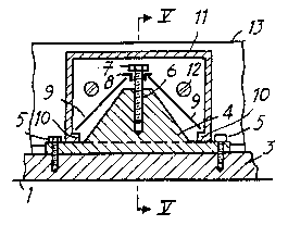
In these figures can be seen the holder ~ in which any
sort of powder, gas or vapour is present and which is pro-
vided with a safety opening 2 which must be closed. Around
this opening a frame 3 is mounted on the holder in any way
whatsoever. On this frame several upright connecting
blocks- 4 'are~mounted at a distance from one another by
means of screws 5. Each connecting block 4 has a-threaded
- opening 6 in which the height of a screw 7 can be set.
This screw passes through an opening which is provided in
- .' : ' . .' ,, ' , .:: : - " . '' ' . :
c~ n ~ f~
W092/06~52 ~d~ W PCT/EPg1/01806
~ .
A
a bearing element 8 the cross section of which is an in-
verted L and on which the head of screw 7, which serves
to preset the tension, can exert pressure. One end of
each of the two diverging straight clip strips 9 which
lie in a plane which runs parallel to the longitudinal
direction of frame 3 engages in this bea,ring element 8.
The other end of each clip strip 9 engages in a clamping
edge 10 provided on the lower edge of each end surface of
a housing 11 the bottom surface of which is open and which ~`',
fits over the connecting block 4 and closes against its
base, so that the whole is adequately protected against
deposits of dirt. ~ach housing 11 is attached by one side
surface by means of screws 12 to the side of a stiff ex-
plosion panel 13 which consists by preference of a compo-
15 site panel such as used in building structures. Each ''
housing 11 is provided with a cover 14 which enables the
clip strips 9 to be easily installed in the housing and
the screw 7 and the supporting element 8 to be adjusted
in height so that preset tension of the clip s'trips 9 and
consequently the clampiny force between the housing 11and the connecting block is adjustable. The pressure at
which the explosion panel will be blown away is determined
by the buckling strength of the clip strips and thus lar- '
gely depends on the material selected and the dimensions
of the clip strips.
~hen an explosion occurs in the holder 1, the generated
pressure exerts upward pressure on the explosion panel 13,
which pressure is transferred by the housings 11 with
clamping edges 10 to the clip strips 9. ~hen the buckling
strength of the clip strips 9 is exceeded, these strips
buckle, so that the explosion ~anel 13 with the housings
11 slides vertically over the connecting~,blocks,,4,,and is
blown away from the safety opening 2 of~ the holder 1.
After a mild explosion~the explosion panel is usually
not damaged and it is sufficient to replace the clip
~, . . "; -
: . . . , ~: .
.. ..
~92/06252 PCT/EP91/01~06
- 5 -
strips and/or the connecting blocks 4 and the housings ll
in order to return the clamping device to service.
It goes without saying that the form, the number and the
dimensions of the components described above may differ
and that some of these components might be replaced by
others which are intended for the same purpose. Thus in-
stead of straight clip strips use could be made of pre-
formed single or multiple clip strips.
.. .
,' .
., - ., . .~
'
,
' ' ' . ' ' ' :. . . ' ,: ~ . '.' ' ' . . ' '''
' ', . ' ' . ' ' , ., ~ - ~ ' , . ,, ' ~ '