Language selection

Search

Patent 2093240 Summary

Third-party information liability

Some of the information on this Web page has been provided by external sources. The Government of Canada is not responsible for the accuracy, reliability or currency of the information supplied by external sources. Users wishing to rely upon this information should consult directly with the source of the information. Content provided by external sources is not subject to official languages, privacy and accessibility requirements.

Claims and Abstract availability

Any discrepancies in the text and image of the Claims and Abstract are due to differing posting times. Text of the Claims and Abstract are posted:

  • At the time the application is open to public inspection;
  • At the time of issue of the patent (grant).
(12) Patent Application: (11) CA 2093240
(54) English Title: BATTING PRACTICE DEVICE
(54) French Title: APPAREIL D'EXERCICE AU BATON
Status: Deemed Abandoned and Beyond the Period of Reinstatement - Pending Response to Notice of Disregarded Communication
Bibliographic Data
(51) International Patent Classification (IPC):
  • A63B 69/00 (2006.01)
(72) Inventors :
  • MALWITZ, LONNIE D. (United States of America)
(73) Owners :
  • LONNIE D. MALWITZ
(71) Applicants :
(74) Agent: BORDEN LADNER GERVAIS LLP
(74) Associate agent:
(45) Issued:
(22) Filed Date: 1993-04-02
(41) Open to Public Inspection: 1994-06-11
Availability of licence: N/A
Dedicated to the Public: N/A
(25) Language of filing: English

Patent Cooperation Treaty (PCT): No

(30) Application Priority Data:
Application No. Country/Territory Date
07/988,772 (United States of America) 1992-12-10

Abstracts

English Abstract


ABSTRACT
A batting practice device is attachable to any of various
existing permanent fixtures. The device includes a shock and
energy absorbing elongate mount bar attachable to the fixture
with a portion of the bar extending therebeyond. A metal
mounting plate is affixed to the portion of the mount bar
which extends beyond the fixture. The metal mounting plate
supports a metal pipe affixed thereto suitably by welding.
The pipe also has a portion extending from beyond the plate
in-line with both the plate and the bar. A metal bushing is
rotatably mounted and captured on the pipe portion extending
from the plate. The metal bushing has a loop extending
outwardly thereon. A piece of braided plastic rope with a
hollow core has a first and second end. A ball is provided
with a central aperture therethrough for passing the first end
of the rope therethrough. The first end is further passed
over the bushing, through the loop, into the hollow core the
rope, through the ball aperture after which the first and
second rope ends are tied into a knot that will not pass
through the ball aperture.


Claims

Note: Claims are shown in the official language in which they were submitted.

- 10 -
THE EMBODIMENTS OF THE INVENTION IN WHICH AN EXCLUSIVE PROPERTY OR
PRIVILEGE IS CLAIMED ARE DEFINED AS FOLLOWS:
1. A batting practice device attachable to various
existing permanent fixtures, such as a fence, post, building,
tree and wall, each with a vertical surface, the device
comprising:
a) a shock and energy absorbing elongate mount bar
releasably attachable to the fixture substantially along
a length of the bar with a portion of the bar extending
beyond the fixture;
b) a metal mounting plate attached to the portion
of the bar beyond the fixture supporting a metal pipe
affixed thereto, the pipe having a portion extending from
the plate in line with both the plate and the bar;
c) a metal bushing rotatably mounted and captured
on the pipe portion extending from the plate, the bushing
having a loop thereon extending outwardly;
d) a piece of braided plastic rope of interweaved
strands with a hollow core having a first end and a
second end; and
e) a ball with a central aperture therethrough,
the first end of the rope passing therethrough and
further passing over the bushing, through the loop, into
the hollow core, through the ball aperture whereat the
first and the second rope ends are tided into a knot that
will not pass through the ball aperture.
2. The batting practice device of claim 1, further
comprising a protective sheath over the rope immediately above
the ball.
3. Claim 1, further comprising a second protective
sheath over the rope at the bushing.
4. Claim 1 wherein the mount bar is a wood board.

- 11 -
5. Claim 1, further comprising a second loop extending
outwardly on the bushing and generally opposite the first
loop, the rope passing through and being captured by both
loops.
6. Claim 1 wherein the metal bushing is captured on the
extending pipe portion by washers.
7. Claim 1, further comprising a counter mounted on the
pipe for counting the revolutions of the bushing.
8. Claim 1, further comprising a vertically adjustable
wall mount between the fixture and the bar.
9. Claim 1, further including grease between the
bushing and the pipe for lubrication.

- 12 -
10. A batting practice device attachable to various
existing permanent fixtures, such as a fence, post, building
tree and wall, each with a vertical surface, the device
comprising:
a) a shock and energy absorbing elongate mount bar
releasably attachable to the fixture substantially along
a length of the bar with a portion of the bar extending
beyond the fixture;
b) a metal mounting plate attached to the portion
of the bar beyond the fixture supporting a metal pipe
affixed thereto, the pipe having a portion extending from
the plate in line with both the plate and the bar;
c) a metal bushing rotatably mounted and captured
on the pipe portion extending from the plate, the bushing
having a loop thereon extending outwardly;
d) a piece of braided plastic rope of interweaved
strands with a hollow core having a first end and a
second end;
e) a ball with a central aperture therethrough,
the first end of the rope passing therethrough and
further passing over the bushing, through the loop, into
the hollow core, through the ball aperture whereat the
first and the second rope ends are tided into a knot that
will not pass through the ball aperture; and
f) a protective sheath over portions of the rope
immediately above the ball and at the bushing.
11. Claim 10 wherein the mount bar is a wood board.
12. Claim 10, further comprising a second loop extending
outwardly on the bushing and generally opposite the first
loop, the rope passing through and being captured by both
loops.
13. Claim 10 wherein the metal bushing is captured on
the extending pipe portion by washers.

- 13 -
14. Claim 10, further comprising a counter mounted on
the pipe for counting the revolutions of the bushing.
15. Claim 10, further comprising a vertically adjustable
wall mount between the fixture and the bar.
16. Claim 10, further including grease between the
bushing and the pipe for lubrication.
17. A batting practice device attachable to various
existing permanent fixtures, such as a fence, post, building,
tree and wall, each with a vertical surface, the device
comprising:
a) a shock and energy absorbing elongate wooden
mount bar releasably attachable to the fixture
substantially along a length of the bar with a portion of
the bar extending beyond the fixture;
b) a metal mounting plate attached to the portion
of the bar beyond the fixture supporting a metal pipe
affixed thereto, the pipe having a portion extending from
the plate in line with both the plate and the bar;
c) metal bushing rotatably mounted and captured on
the pipe portion extending from the plate, the bushing
having first and second generally opposite loops thereon
extending outwardly;
d) a piece of braided plastic rope of interweaved
strands with a hollow core having a first end and a
second end; and
e) a ball with a central aperture therethrough,
the first end of the rope passing therethrough and
further passing over the bushing, through the loop, into
the hollow core, through the ball aperture whereat the
first and the second rope ends are tided into a know that
will not pass through the ball aperture.

- 14 -
18. The batting practice device of claim 17, further
comprising a protective sheath over the rope immediately above
the ball.
19. Claim 17, further comprising a second protective
sheath over the rope at the bushing.
20. Claim 17 wherein the mount bar is a wood board.
21. Claim 17 wherein the metal bushing is captured on
the extending pipe portion by washers.
22. Claim 17, further comprising a counter mounted on
the pipe for counting the revolutions of the bushing.
23. Claim 17, further comprising a vertically adjustable
wall mount between the fixture and the bar.
24. Claim 17, further including grease between the
bushing and the pipe for lubrication.

- 15 -
25. A batting practice device attachable to various
existing permanent fixtures, such as a fence, post, building,
tree and wall, each with a vertical surface, the device
comprising:
a) a shock and energy absorbing elongate mount
wooden bar releasably attachable to the fixture
substantially along a length of the bar with a portion of
the bar extending beyond the fixture;
b) a metal mounting plate attached to the portion
of the bar beyond the fixture supporting a metal pipe
affixed thereto, the pipe having a portion extending from
the plate in line with both the plate and the bar;
c) a metal bushing rotatably mounted and captured
on the pipe portion extending from the plate with grease
between the bushing and the bar, the bushing having first
and second generally opposite loops thereon extending
outwardly;
d) a piece of braided plastic rope of interweaved
strands with a hollow core having a first end and a
second end;
e) a ball with a central aperture therethrough,
the first end of the rope passing therethrough and
further passing over the bushing, through the loop, into
the hollow core, through the ball aperture whereat the
first and the second rope ends are tided into a know that
will not pass through the ball aperture; and
f) a protective sheath over portions of the rope
immediately above the ball and at the bushing; and
g) a counter mounted on the pipe for counting
revolutions of the ball and the bushing.

Description

Note: Descriptions are shown in the official language in which they were submitted.


209324~)
-- 2
BACKGROUND OF THE XNVENTION
This invention relates to a batting practice device, and
more particularly, to an improved batting practice device that
is more inexpensive, durable and long lived than other prior
batting practice device.
In general, such batting practice devices are a necessary
tool to permit a ball player to practice daily, if desired,
hitting a ball within the hitable strike zone for the baseball
player. These devices permit the user to train his body, arms
and eyes. An observer may coach the user with respect to the
proper body stance and balance in learning and adapting the
proper body mechanics for batting. With the aid of batting
practice devices, an individual can learn to transfer his
weight into hitting the ball, to slug the ball hard, to become
a switch hitter and to develop confidence in a sense to see,
hear and feel the crisp hard hit of a correctly batted ball.
There are, of course, many baseball and softball batting
practice devices known in the prior art. The prior art
devices are not completely satisfactory in all respects and do
not provide the same flexibility, portability and overall
advantages of the present invention. Such prior art devices
are quite extravagant and complex rendering them quite
expensive and not readily available to the average young
baseball player for practice at home. Other types of batting
devices appear somewhat flimsy and not durable thereby having
a shortened life when compared to the present invention.
There is a need for a batting practice device that is
easy to manufacture and relatively inexpensive, thereby making
it available to young players as well as the older avid
baseball and softball player enthusiast. The device must be
of a durable construction as to not deteriorate or wear out
upon the practicing hitters repeated inability to not directly

2093240
.
-- 3
hit the ball, but to hit other parts of the device. The
device, therefore, must not only be durable but be of a long
life construction that can take the hard abuse that the a
training and learniny baseball player may inflict on the
batting practice device.
SUMM~RY OF THE INVENTION
A batting practice device is attachable to any of various
existing permanent fixtures. The device includes a shock and
energy absorbing elongate mount bar attachable to the fixture
with a portion of the bar extending therebeyond. A metal
mounting plate is affixed to the portion of the mount bar
which extends beyond the fixture. The metal mounting plate
supports a metal pipe affixed thereto suitably by welding.
The pipe also has a portion extending from beyond the plate
in-line with both the plate and the bar. A metal bushing is
rotatably mounted and captured on the pipe portion extending
from the plate. The metal bushing has a loop extending
outwardly thereon. A piece of braided plastic rope with a
hollow core has a first and second end. A ball is provided
with a central aperture therethrough for passing the first end
of the rope therethrough. The first end is further passed
over the bushing, through the loop, into the hollow core the
rope, through the ball aperture after which the first and
second rope ends are tied into a knot that will not pass
through the ball aperture.
A principle object and advantage of the present invention
is that it is of an extremely durable and long lived
construction while yet remaining relatively simple, easy and
inexpensive to manufacture.
Another object and advantage of the present invention is
that the device can be mounted on any of a variety of
:

2~93~0
permanent fixtures, such as a fence, post, building, tree or
wall.
Another object and advantage is that the elongate mount
bar of the device absorbs the impact, shock, vibration and
energy forces transferred through the device which otherwise
would be passed on through to the permanent fixture.
Another object and advantage of the present invention is
that the device may be removed from the permanent fixture for
safe keeping or transfer to another location.
BRIEF DESCRIPTION OF THE DRAWINGS
Figure 1 is a front elevational view of the batting
practice device of the present invention being utilized by a
batter as the device is affixed to a fence;
Figure 2 is a front elevational view of the present
invention with the elongate mounting bar broken away;
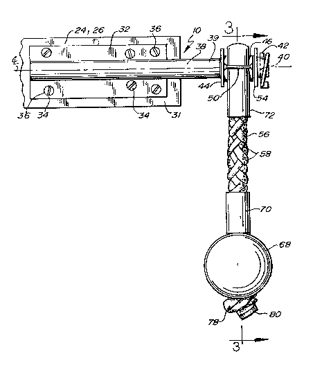
Figure 3 is a cross-sectional view taken along lines 3-3
of Figure 2;
Figure 3A is a front elevational view of the guide tool
utilized in constructing the present invention; ::
Figure 4 is a front elevational view of the batting
practice device mounted on fence posts;
Figure 5 is a front elevational view of the batting :
practice device mounted on an exterior wall of a building; ~:
Figure 6 is a front elevational view of the batting
practice device mounted on to two adjacent trees;

20~32~0
- 5
Figure 7 is a front elevational view of the batting
practice device mounted on the interior side of a wall shown
in cross-section; and
Figure 8 is a front elevational view of the batting
practice device partially broken away showing a revolution
counter mechanism mounted thereon.
DETAILED SPECIFICATION
The batting practice device 10 of the present invention
may generally be seen in Figures 1-8. The device attaches to
some existing permanent fixtures 12 with a vertical surface
for suspending the batting practice device 10. The device
includes an elongate mount bar 24, mounting plate 32, pipe 38,
metal bushing 46, braided rope 56 and ball 68.
While the detailed structure assembly and operation of
the batting practice device 10 is clearly shown in
Figures 1-3A, samples of permanent fixtures 12 are shown in
Figures 4-7. Examples of permanent fixtures might include a
fence 14, posts 16, building 18, trees 20 and an interior
wall 22.
More specifically, the batting practice device 10
includes an elongate mount bar 24 suitably made of a "2 x 4"
board 26 approximately four feet in length. The bar 24 may be
made of a variety of materials but Applicant has found that
the wooden board 26 readily absorbs the impact, shock,
vibration and energy forces which a batter will transfer from
his bat (Figure 1) to the device which otherwise may be
transferred to the permanent fixture 12.
The mount bar 24 is appropriately releasably affixed or
attached to the permanent fixture 12 by way of six inch hanger
bolts 28 or the like. The bolts 28 are appropriately attached

209324~
-
- 6 -
to the fixture perhaps in several vertically aligned locations
for adjusting the batting practice device 10 either upwardly
or downwardly to the strike zone of the user.
Approximately 3/4 of the length mount bar 24 is to be
mounted flush onto the vertical surface of the permanent
fixture 12, where applicable. The bar 24 has apertures
therethrough which receive the hanger bolts 28 therethrough.
Thereafter washers and wingnuts may be rotatably affixed to
the bolts to secure the mount bar 24 to the fixture 12. The
mount bar 24 by this arrangement has a bar extending
portion 31 approximating 1/4 of the length of the overall
mount bar 24.
At the bar extending portion 31 is appropriately affixed
a mounting plate 32 which suitably is made of a zinc-plated
heavy gauge steel. The plate 32 appropriately may be affixed
to the bar extending portion 31 by way of screws, bolts or the
like 36 at the plate's apertures 34.
Suitably affixed to the mounting plate 32, such as by
welding, is a zinc-plated heavy gauge steel rod or pipe 38
which has a pipe extending portion 39 and an aperture 40
through the end of that portion 39. The aperture 40 receives
a locking lynch pin 42 while intermediately of the pipe
extending portion 39 is a stop washer 44 which is welded to
the pipe 38.
A metal bushing 46 is also appropriately made of a zinc-
plated heavy gauge steel. The metal bushing 46 may have
grease 48 on its inner side for a low friction fit and to add
lubrication as the bushing 46 is slid over and rotated on the
pipe extending portion, stopped by the stop washer 44 and
locked into place the lynch pin 42. The metal bushing 46
preferably has a first loop, ring or eyelet 50 and a generally
opposing second loop, ring or eyelet 52 as will be

2~932~0
.
-- 7
appreciated. Be~ween the bushing 46 and the lynch pin 42 is
appropriately located a fender washer 54 to prohibit wear of
the pin 42 by the friction of the rotating metal bushing 46.
A braided plastic rope 56 is utilized with this invention
and is suitably made of a plastic, nylon or polypropylene
material with lnterweave strands 58. A braided rope 56 of
this type typically has a hollow core 60. The rope 56 may
have a first end 62 and a second end 64. The rope is to pass
through the central aperture 66 of a ball 68, suitably of the
equivalent weight of a softball or baseball and appropriately
made of ethylene vinyl acetate. The braided rope 56
appropriately is protected by a first vinyl sheath 70 located
just above the ball 68 and second vinyl sheath rope guard or
protector 72 which surrounds the braided rope at the metal
bushing 46 area.
Referring to Figures 3 and 3A, the assembly of the
batting practice device 10 may be understood. The first
end 62 of braided rope 56 is initially fed through the central
apertures 66 of the ball 68. Thereafter the first vinyl
sheath 70 is threaded over the first end 62 and slid
downwardly to abut the ball 68. The first end 62 is then
thread through the second vinyl sheath 72 which together with
the braided rope is passed over the metal bushing 46 and
through the first and second loops or rings 52. Thereafter,
the first end 62 is inserted into the pointed hollow needle or
guide tool 74. The pointed tool 74 is then inserted into the
hollow core 60 of the braided rope 56 between the interweaved
strands 58. The first end is guided along and within the
hollow core as it is passed through the central aperture 66 of
ball 68. Thereafter a knot 78 if formed suitably at the
first 62 and second 64 ends after which the ends are heat
sealed 80 together.

2093~40
-- 8
Next the lynch pin 42 is removed from the end of pipe 38.
The metal bushing 46 is slid onto the pipe extending
portion 39 up to the stop washer 44. Thereafter, fender
washer 44 is slid onto pipe 38 and lynch pin 42 is again
locked onto the pipe 38. The invention thereafter is
assembled excepting only the affixation of the mounting
plate 32 onto the elongate mount bar 24 or board 26 which in
turn is affixed to a permanent fixture 12.
Figures 1 and 4 through 7 illustrate the various
permanent fixtures 12 that the batting practice device 10 may
be releasably connected thereto. It is appropriate to note
that a plurality hanger bolts 28 may be vertically aligned as
to move the elongate bar 24 either upwardly or downwardly to
position the ball 68 in the strike zone of the batting
operator.
Referring to Figure 1, the batting operator, and perhaps
a coach, can observe the rotation of the ball 68 and tell if
the hit was popped up, pushed, pulled or slugged hard and
straight forward from either behind or in front of the
operator.
Figure 7 shows an adjustable wall mount 82 for the inside
of a building such as a gym. Hanger bolts or studs 84 are
affixed into the wall 22. The bolts or studs 84 appropriately
support an outer tube or sleeve 86 in a secure manner.
Sleeve 86 supports a set screw with a handle 88. A device
support rod 90 passes through the sleeve 86 and is adjustably
held in vertical position by the inward turning of the set
screw 88. Arrow A illustrates that the device support rod 90
may be moved upwardly or downwardly to appropriately position
the ball 68 in the user's strike zone.
Referring to Figure 8, the present invention may be
fitted with a counter 94. Counter 94 is appropriately affixed

2~932~
.. g
.
to the pipe 38 adjacent a collar or washer 102 which takes the
place of former stop washer 44. In place of former stop
washer 44, a washer 96 is fixed to bushing 46 and supports a
cog 98. As bushing 46 rotates about pipe 38, the cog 98
extending from washer 96 engages the sprocket of counter 100.
By this arrangement, the user or batting practitioner may
count the number of revolutions of both the ball 68 and the
bushing 46 to ascertain the force that the user has hit the
ball 68. It is also appropriate that ball 68 be of
substantially the same weight as a real baseball or softball
to give the user the sensation of actually hitting a real
ball.
The present invention may be embodied in other specific
forms without departing from the spirit or essential
attributes thereof; therefore, the illustrated embodiment
should be considered in all respects as illustrative and not
restrictive, reference being made to the appended claims
rather than to the foregoing description to indicate the scope
of the invention.

Representative Drawing
A single figure which represents the drawing illustrating the invention.
Administrative Status

2024-08-01:As part of the Next Generation Patents (NGP) transition, the Canadian Patents Database (CPD) now contains a more detailed Event History, which replicates the Event Log of our new back-office solution.

Please note that "Inactive:" events refers to events no longer in use in our new back-office solution.

For a clearer understanding of the status of the application/patent presented on this page, the site Disclaimer , as well as the definitions for Patent , Event History , Maintenance Fee  and Payment History  should be consulted.

Event History

Description Date
Time Limit for Reversal Expired 1999-04-06
Application Not Reinstated by Deadline 1999-04-06
Deemed Abandoned - Failure to Respond to Maintenance Fee Notice 1998-04-02
Application Published (Open to Public Inspection) 1994-06-11

Abandonment History

Abandonment Date Reason Reinstatement Date
1998-04-02

Maintenance Fee

The last payment was received on 

Note : If the full payment has not been received on or before the date indicated, a further fee may be required which may be one of the following

  • the reinstatement fee;
  • the late payment fee; or
  • additional fee to reverse deemed expiry.

Please refer to the CIPO Patent Fees web page to see all current fee amounts.

Fee History

Fee Type Anniversary Year Due Date Paid Date
MF (application, 2nd anniv.) - small 02 1995-04-03
Owners on Record

Note: Records showing the ownership history in alphabetical order.

Current Owners on Record
LONNIE D. MALWITZ
Past Owners on Record
None
Past Owners that do not appear in the "Owners on Record" listing will appear in other documentation within the application.
Documents

To view selected files, please enter reCAPTCHA code :


To view images, click a link in the Document Description column. To download the documents, select one or more checkboxes in the first column and then click the "Download Selected in PDF format (Zip Archive)" or the "Download Selected as Single PDF" button.

List of published and non-published patent-specific documents on the CPD .

If you have any difficulty accessing content, you can call the Client Service Centre at 1-866-997-1936 or send them an e-mail at CIPO Client Service Centre.


Document
Description 
Date
(yyyy-mm-dd) 
Number of pages   Size of Image (KB) 
Claims 1994-06-11 6 296
Cover Page 1994-06-11 1 65
Abstract 1994-06-11 1 51
Drawings 1994-06-11 2 120
Descriptions 1994-06-11 8 479
Representative drawing 1998-08-10 1 18
Courtesy - Abandonment Letter (Maintenance Fee) 1998-04-30 1 186
Fees 1997-04-01 1 47
Fees 1996-04-02 1 23
Fees 1995-03-06 1 54