Language selection

Search

Patent 2093446 Summary

Third-party information liability

Some of the information on this Web page has been provided by external sources. The Government of Canada is not responsible for the accuracy, reliability or currency of the information supplied by external sources. Users wishing to rely upon this information should consult directly with the source of the information. Content provided by external sources is not subject to official languages, privacy and accessibility requirements.

Claims and Abstract availability

Any discrepancies in the text and image of the Claims and Abstract are due to differing posting times. Text of the Claims and Abstract are posted:

  • At the time the application is open to public inspection;
  • At the time of issue of the patent (grant).
(12) Patent Application: (11) CA 2093446
(54) English Title: FLUID TREATMENT APPARATUS
(54) French Title: APPAREIL DE TRAITEMENT DE FLUIDES
Status: Deemed Abandoned and Beyond the Period of Reinstatement - Pending Response to Notice of Disregarded Communication
Bibliographic Data
(51) International Patent Classification (IPC):
  • C02F 1/48 (2006.01)
  • B01J 19/08 (2006.01)
  • F02M 27/04 (2006.01)
(72) Inventors :
  • HAYES, JOHN (United Kingdom)
(73) Owners :
  • TARN PURE LIMITED
(71) Applicants :
  • TARN PURE LIMITED (United Kingdom)
(74) Agent: MARKS & CLERK
(74) Associate agent:
(45) Issued:
(86) PCT Filing Date: 1991-10-07
(87) Open to Public Inspection: 1992-04-16
Examination requested: 1998-10-07
Availability of licence: N/A
Dedicated to the Public: N/A
(25) Language of filing: English

Patent Cooperation Treaty (PCT): Yes
(86) PCT Filing Number: PCT/GB1991/001740
(87) International Publication Number: WO 1992006042
(85) National Entry: 1993-04-05

(30) Application Priority Data:
Application No. Country/Territory Date
9021717.5 (United Kingdom) 1990-10-05
9023224.0 (United Kingdom) 1990-10-25

Abstracts

English Abstract

2093446 9206042 PCTABS00011
An apparatus for magnetically treating fluids such as water and
hydrocarbon fuels; in the case of water to increase the solubility
of salts and reduce scale or soften any deposits which are
formed, and in the case of hydrocarbons to increase fuel combustion
efficiency. The apparatus improves on existing techniques by
including first and second magnetisation means mounted on a
fluid-carrying non-metallic pipe, the first generating a constant magnetic
field in the fluid and the second generating an alternating
magnetic field in the fluid, and superimposed on the constant field.
The simultaneous use of alternating and constant fields enhances
the aforementioned effects as compared with a constant field alone.
The frequency of the alterning field is varied to obtain the
optimum results.


Claims

Note: Claims are shown in the official language in which they were submitted.

WO 92/06042 PCT/GB91/01740
-8-
CLAIMS:
1. A fluid treatment apparatus, comprising:
a first magnetisation means for generating a
constant magnetic field of predetermined intensity, and
adapted to be mounted on a conveyance in a fluid system;
a second magnetisation means for generating an
alternating magnetic field of predetermined frequency
and adapted to be mounted on the conveyance in close
proximity to the first magnetising means;
wherein the alternating magnetic field is
superimposed on the constant magnetic field within the
conveyance.
2. An apparatus according to claim 1, wherein:
the first and second magnetisation means
include one or more magnetisation coils mounted
separately or in a single assembly around the periphery
of the conveyance.
3. An apparatus according to claim 1 or 2
wherein:
each magnetisation means comprises a single
magnetisation coil or a pair of diametrically opposed
magnetisation coils, mounted around the periphery of the
conveyance.
4. An apparatus according to claim 1, 2 or 3,
wherein:
the magnetisation coils of the first and
second magnetisation means are wound one on top of the
other or disposed at longitudinally adjacent points on
the conveyance.

WO 92/06042 PCT/GB91/01740
-9-
5. An apparatus according to any of claims 1 to
4, wherein:
the first and second magnetisation means
include magnetisation coils and one or more magnetic
pole pieces mounted on the conveyance, the pole
pieces(s) being disposed within or adjacent the
magnetisation coils.
6. An apparatus according to any of the preceding
claims, wherein:
said first or second magnetisation means
includes two magnetisation coils connected in series and
mounted diametrically apposite each other around the
periphery of the conveyance, and
the magnetisation coils are connected to a
single power source.
7. An apparatus according to any of claims 2 to
5, wherein:
the magnetisation coils are connected to
separate power sources.
8. An apparatus according to any of the preceding
claims, wherein:
the first magnetisation means includes means
for varying the intensity of the constant magnetic
field.
9. An apparatus according to any of the preceding
claims, wherein:
the second magnetisation means includes means
for varying the frequency of the alternating magnetic
field.
10. An apparatus according to any of the preceding

WO 92/06042 PCT/GB91/01740
-10-
claims, wherein:
the conveyance comprises a pipe formed of a
non-metallic material.
11. An apparatus substantially as hereinbefore
described with reference to Figs. 1 to 5 of the
accompanying drawings.

Description

Note: Descriptions are shown in the official language in which they were submitted.


W092/0~2 PCT/GB91/01740
~S ~ 6 1 '
Fluid Treatment Apparatus
The invention relates to a fluid treatment
apparatus and in particular to a magnetic fluid
treatment apparatus in which the properties of a fluid
and/or materials dissolved therein are altered by -
passing the fluid through a magnetic field.
It has long been recognized that when a
magnetic field is applied to hard water it has the
effects of~ increasing the solubility of salts of,
for example, calcium, which may be deposited as scale:
and ~2) changing the structure of any deposits :hat do
appear so that they remain soft and do not form the
typical hard scale.
Existing devices which exploit this effect
have employed permanent magnets and electromagnets to
generate magnetic fields but the resultant effects have
proved to be extremely variable: in some cases the
amount of scale has been considerably reduced, whilst
in others little effect has been observed. It is
believed that the causes of this are the wide variations
in water balance (ph, hardness, and the composition of
materials present in the water).
. .

:
WO ~/0UJ2 ~ PCT/C~9l/0l7
A magnetic water treatment apparatus is
disclosed in US Patent 4,485,012, in which a first coil,
mounted on a pipe between a water source and a filter,
produces an alternating magnetic field, generating
mechanical vibrations in a pair of metal plates between
which a flow of water passes and thereby causing
mechanical perturbations in the water. A second coil,
mounted on a pipe between the filter and pressure tank ~ -
and remote from the first coil, is coupled to a d.c.
signal which produces a constant magnetic field in the
pipe through which the water passes in order to alter -
the solubility of salts in the water.
In the water treatment apparatus of the
present invention a strong alternating magnetic field
and a strong constant magnetic field, superimposed on
the alternating field, are generated in the vicinity of
the water being treated. This is because a constant
field alone may not completely align the structure of
the salts dissolved in the water and produce the desired
effects of reducing scale deposits. On the other hand,
the simultaneous use of the alternating field enhances
the efficiency of the constant field by "freeing" the
salts in solution so that they may more easily have
their structures aligned by the constant field.
Desirable effects have also been exploited in
the magnetic treatment of liquid fuels such as oil,
diesel and petrol which undergo combustion in, for
example, boilers and motor vehicle engines, and it has
been found with existing apparatus that the efficiency
with which such fuels are burnt may be increased when
they are passed through a constant magnetic field.
However, it is believed that the full
advantages of magnetic treatment of hydrocarbon fuels
may not have been realised by such use of a constant
magnetic field alone.
' `, .~ , .,- .,, '; . ~ ~ ,, -
' - : ''' . ~ .,"' ." ': . ' ~ , -
;

W092/~W2 2 ~Q~ PCT/CB91/01740
-3-
The present invention, in a similar manner to
the water treatment apparatus mentioned above improves
on existing magnetic f~el treatment devices by
generating a strong alternating magnetic field and a
strong constant magnetic field superimposed on the
alternating field in the fuel being treated. Such
treatment, which is applicable to both liquid and
gaseous fuels, improves the~fuel combustion efficiency
on existing levels.
The present invention provides a fluid
treatment apparatus, comprising: first magnetisation
means for generating a constant magnetic field of
pre-determined intensity, and adapted to be mounted on a
conveyance in a fluid system; second magnetisation means
for producing an alternating magnetic field of pre-
determined frequency and adapted to be mounted in close
proximity to the first magnetisation means.
The first and second magnetisation means
preferably comprise one or more coils either in a single
assembly or mounted separately around the periphery of a
non-magnetic (e.g. plastic) pipe through which water is
passed. Each magnetisation means may comprise a single
coil, or a pair of coils mounted opposite each other
around the circumference of the pipe.
The first and second magnetisation coils may
be wound one on top of the other (layer wound) at the
same point on a pipe, or may be mounted at
longitudinally adjacent points on the pipe, in a manner
similar to the arrangement of horizontal and vertical
deflection coils of a cathode ray tube.
In order to concentrate the flux of the
magnetic field within the fluid flow, magnetic pole
pieces are preferably mounted on the pipe, within or
adjacent the coil windings.
.,
.. :;. . . :. .,:
. .
-

W092/~2 ~ ~ PCT/GB91/01740
--4--
~ he coil assembly may include two coils
connected in series and mounted (with respective pole
pieces) opposite each other around the circumference of
the pipe, effectively forming a single circuit driven by
one source of power. Alternatively, each coil may be
driven by a separate power source.
Power is supplied to the coils from a control
unit which supplies a constant d.c. current to the first
magnetisation coils, the current being adjustable to
optimise the effect of realigning the structure of the
salts dissolved in the water. The control unit also
supplies an alternating current to the second
magnetisation coils, and the magnitude and frequency of
the alternating current may be adjusted, the latter from
"mains" frequencies of 50-60Hz up to 500RHz or more in
order to obtain the greatest efficiency.
Embodiments of the present invention will now
be described, by way of example only where the fluid is
water (or an aqueous solution), with reference to the
accompanying drawings, in which:
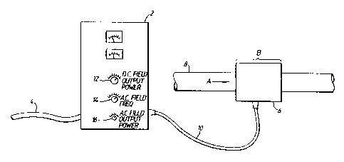
Figure 1 is a diagram of the general
arrangement of the water treatment apparatus of the
present invention in relation to a water-carrying pipe;
Figure 2 illustrates a coil assembly mounted
on a water-carrying pipe in a first embodiment of the
present invention, ~a) as a side view, and (b) as a plan
view;
Figure 3 shows a coil assembly mounted on a
water-carrying pipe in a second embodiment of the
present invention;
Figure 4 illustrates a coil assembly mounted
on a water-carrying pipe in a third embodiment of the
present invention;
Figure 5 shows alternative methods of
increasing the flux within the water-carrying pipe in
- . . ~ . ~ - , . , . , . ~
.. , ~, , , . . . . . ~:
,: . ,.. . , : .
.. . . . .. .
. , . . ;:.

W092/~2 PCT/GB91/01740
-5~
the embodiments of the invention, (a) using a magnetic
pole pieces, and (b~ using an overwound coil along the
periphery of the magnetisation coils.
A fluid treatment apparatus for the ease of
fluids other than water (or aqueous solutions) has the
same construction as the water treatment apparatus shown
in, and described with reference to, Figures 1 to 5,
save that the fluid flowing in the pipe 8 is a liquid or
vapour such as oil, diesel or petrol, or a mixture
containing such fuels.
The water treatment apparatus according to the
present invention is illustrated in Figure 1. In this
apparatus, a control unit 2 is supplied with power from
the main's supply via a main's lead 4, and the control
unit 2 in turn supplies power to a coil assembly 6,
mounted around the periphery of a plastic water-carrying
pipe 8, via a multi-conductor cable 10. The control
unit 2 is provided with controls 12, 14, 16 for
adjustinq the d.c. output power to the constant-field
coil(s), the frequency of the alternating field, and the
a.c. output power to the alternating-field coil~s),
respectively. The water flows in the pipe in the
direction of the arrow A and comes under the influence
of the magnetic fields when present in the region B.
In Figures 2(aJ and ~b), respectively, side
and plan views of the coil assembly 6 of a first
embodiment of the present invention are shown. The coil
assembly 6 comprises a first multi-winding magnetisation
coil 18 and associated pole piece 20 (made of a
ferromagnetic material); and a second multi-winding
magnetisation coil 22 and associated pole piece 24.
~oth the coils 18, 22 and the pole pieces 20, 24 are
arcuate in cross-section so as to enable them to be
snugly mounted on the outer wall of the pipe 8. The
first coil 18 is supplied with a direct current from the
... . . . : . ,
, . , :
. . ,. , , , ~ . .

W092/~2
PCT/GB91/01740
~ 6-
control unit 2 via the cable 10 and generates a constant
magnetic field. The second coil 22 is supplied with an
alternating current from the control unit 2 via the
cable 10, and generates an alternating magnetic field.
Referring to Fig. 3, the coil assembly 6 of a
second embodiment of the present invention is shown and
comprises a first multi-turn magnetisation coil 26,
wound about an axis perpendicular to the direction of
elongation of the pipe 8, attached to a ferromagnetic
pole piece 28 and mounted on the outer wall of the pipe
8. The coil assembly 6 also comprises a second multi-
turn coil 30 (wound in the same manner as the coil 26)
attached to a pole piece 32 and mounted diametrically
opposite the coil 26 on the outer wall of the pipe 8.
The first and second coils 26, 30 generate constant and
alternating magnetic fields, respectively, as in the
first embodiment described with reference to Fig. 2.
Figure 4 shows a coil assembly 6 of a third
embodiment of the present invention which comprises two
coils 34, 38 and two pole pieces 36, 40 which are
identical to the coils 18, 22 and pole pieces 20, 24 of
the first embodiment described with reference to Fig. 2.
However, the first ~34) and second ~38) magnetisation
coils are mounted immediately adjacent each other on the
outer wall of the pipe 8, rather than diametrically
opposite each other. The first and second coils 34, 38
generate constant and alternating magnetic fields,
respectively, as in the first embodiment described with
reference to Fig. 2.
Referring to Fig. 5, a cross-section through
the pipe and coil assembly is shown in the first
embodiment, and illustrates the arrangement of the coils
18, 22 and pole pieces 20, 24 which enables the magnetic
flux density in the core 41 of the water carrying pipe 8
to be maximised. The coils and pole pieces are arranged
~.. , ': . .:

W092/0~42 PCT/GB91/01740
_7_ ~93~e
in a similar manner in the third embodiment.
An alternative arrangement for optimising flux
density inside the pipe 8 is shown in Fig. S(b), in
which the first and second magnetisation coils 42, 44
and identical to the first and second coils 18, 22 of
the first embodiment. However, the pole pieces 20, 24
are omitted and replaced by a multi-turn coil 46 which
is wound around the outside of the coils 42, 44 about
the axis of the pipe 8. The coil 46 is not supplied
with any current, but rather forms a pole performing the
same function as the pole pieces 20, 24.
. : . . . . .

Representative Drawing
A single figure which represents the drawing illustrating the invention.
Administrative Status

2024-08-01:As part of the Next Generation Patents (NGP) transition, the Canadian Patents Database (CPD) now contains a more detailed Event History, which replicates the Event Log of our new back-office solution.

Please note that "Inactive:" events refers to events no longer in use in our new back-office solution.

For a clearer understanding of the status of the application/patent presented on this page, the site Disclaimer , as well as the definitions for Patent , Event History , Maintenance Fee  and Payment History  should be consulted.

Event History

Description Date
Inactive: IPC from MCD 2006-03-11
Application Not Reinstated by Deadline 2003-10-07
Time Limit for Reversal Expired 2003-10-07
Deemed Abandoned - Failure to Respond to Maintenance Fee Notice 2002-10-07
Amendment Received - Voluntary Amendment 2002-07-15
Inactive: S.30(2) Rules - Examiner requisition 2002-01-15
Letter Sent 2001-11-01
Reinstatement Requirements Deemed Compliant for All Abandonment Reasons 2001-10-22
Deemed Abandoned - Failure to Respond to Maintenance Fee Notice 2001-10-09
Letter Sent 1999-11-09
Reinstatement Requirements Deemed Compliant for All Abandonment Reasons 1999-11-02
Deemed Abandoned - Failure to Respond to Maintenance Fee Notice 1999-10-07
Inactive: Correspondence - Formalities 1999-02-05
Inactive: RFE acknowledged - Prior art enquiry 1998-10-27
Inactive: Status info is complete as of Log entry date 1998-10-27
Inactive: Application prosecuted on TS as of Log entry date 1998-10-27
All Requirements for Examination Determined Compliant 1998-10-07
Request for Examination Requirements Determined Compliant 1998-10-07
Letter Sent 1998-03-04
Reinstatement Requirements Deemed Compliant for All Abandonment Reasons 1998-02-24
Deemed Abandoned - Failure to Respond to Maintenance Fee Notice 1997-10-07
Application Published (Open to Public Inspection) 1992-04-16

Abandonment History

Abandonment Date Reason Reinstatement Date
2002-10-07
2001-10-09
1999-10-07
1997-10-07

Maintenance Fee

The last payment was received on 2001-10-22

Note : If the full payment has not been received on or before the date indicated, a further fee may be required which may be one of the following

  • the reinstatement fee;
  • the late payment fee; or
  • additional fee to reverse deemed expiry.

Please refer to the CIPO Patent Fees web page to see all current fee amounts.

Fee History

Fee Type Anniversary Year Due Date Paid Date
Reinstatement 1998-02-24
MF (application, 6th anniv.) - standard 06 1997-10-07 1998-02-24
Request for examination - standard 1998-10-07
MF (application, 7th anniv.) - standard 07 1998-10-07 1998-10-07
MF (application, 8th anniv.) - standard 08 1999-10-07 1999-11-02
Reinstatement 1999-11-02
MF (application, 9th anniv.) - standard 09 2000-10-09 2000-09-25
Reinstatement 2001-10-22
MF (application, 10th anniv.) - standard 10 2001-10-09 2001-10-22
Owners on Record

Note: Records showing the ownership history in alphabetical order.

Current Owners on Record
TARN PURE LIMITED
Past Owners on Record
JOHN HAYES
Past Owners that do not appear in the "Owners on Record" listing will appear in other documentation within the application.
Documents

To view selected files, please enter reCAPTCHA code :


To view images, click a link in the Document Description column. To download the documents, select one or more checkboxes in the first column and then click the "Download Selected in PDF format (Zip Archive)" or the "Download Selected as Single PDF" button.

List of published and non-published patent-specific documents on the CPD .

If you have any difficulty accessing content, you can call the Client Service Centre at 1-866-997-1936 or send them an e-mail at CIPO Client Service Centre.


Document
Description 
Date
(yyyy-mm-dd) 
Number of pages   Size of Image (KB) 
Representative drawing 1998-08-07 1 8
Representative drawing 2003-06-30 1 5
Abstract 1995-08-17 1 72
Description 1994-04-30 7 242
Cover Page 1994-04-30 1 21
Drawings 1994-04-30 2 45
Claims 1994-04-30 3 77
Claims 2002-07-15 2 65
Courtesy - Abandonment Letter (Maintenance Fee) 1997-11-04 1 185
Notice of Reinstatement 1998-03-04 1 172
Reminder - Request for Examination 1998-06-09 1 117
Acknowledgement of Request for Examination 1998-10-27 1 172
Courtesy - Abandonment Letter (Maintenance Fee) 1999-11-04 1 184
Notice of Reinstatement 1999-11-09 1 171
Courtesy - Abandonment Letter (Maintenance Fee) 2001-11-01 1 183
Notice of Reinstatement 2001-11-01 1 171
Courtesy - Abandonment Letter (Maintenance Fee) 2002-11-04 1 179
PCT 1993-04-05 9 262
Correspondence 1999-02-05 1 35
Fees 1998-10-07 1 52
Fees 1999-11-02 1 61
Fees 2001-10-22 1 58
Fees 1994-11-10 4 182
Fees 1998-02-24 2 71
Fees 1995-10-06 1 47
Fees 1996-09-30 1 60
Fees 1995-01-04 1 47
Fees 1993-04-05 1 55