Language selection

Search

Patent 2093593 Summary

Third-party information liability

Some of the information on this Web page has been provided by external sources. The Government of Canada is not responsible for the accuracy, reliability or currency of the information supplied by external sources. Users wishing to rely upon this information should consult directly with the source of the information. Content provided by external sources is not subject to official languages, privacy and accessibility requirements.

Claims and Abstract availability

Any discrepancies in the text and image of the Claims and Abstract are due to differing posting times. Text of the Claims and Abstract are posted:

  • At the time the application is open to public inspection;
  • At the time of issue of the patent (grant).
(12) Patent: (11) CA 2093593
(54) English Title: CABLE WITH LIGHT WAVEGUIDE TUBES IN A MATRIX
(54) French Title: CABLE SOUS TUBES GUIDE D'ONDE LUMINEUSE DISPOSES EN MATRICE
Status: Expired and beyond the Period of Reversal
Bibliographic Data
(51) International Patent Classification (IPC):
  • G02B 6/02 (2006.01)
  • G02B 6/44 (2006.01)
(72) Inventors :
  • WAGMAN, RICHARD S. (United States of America)
(73) Owners :
  • SIECOR CORPORATION
(71) Applicants :
  • SIECOR CORPORATION (United States of America)
(74) Agent: GOWLING WLG (CANADA) LLP
(74) Associate agent:
(45) Issued: 1996-12-03
(22) Filed Date: 1993-04-07
(41) Open to Public Inspection: 1993-10-14
Examination requested: 1993-04-07
Availability of licence: N/A
Dedicated to the Public: N/A
(25) Language of filing: English

Patent Cooperation Treaty (PCT): No

(30) Application Priority Data:
Application No. Country/Territory Date
07/867,644 (United States of America) 1992-04-13

Abstracts

English Abstract


A simplified loose tube fiber optic cable, and a method for making the cable,
is disclosed. A plurality of transmission units, each including a plurality of light
waveguides and filling compound in a buffer tube, are provided. The transmission
units are stranded together with a plurality of tensile yarns coated with a hardenable
material. After the hardenable material is cured, an outer tube is extruded over the
buffer tubes and coated tensile yarns.


Claims

Note: Claims are shown in the official language in which they were submitted.

What is claimed is:
1. An optical transmission cable containing no rod-like central strength member,
comprising a plurality of transmission units in an outer tube, each transmission unit
comprising a filling compound and a plurality of light waveguides loosely disposed in
a buffer tube; and a plurality of tensile yarns embedded in a matrix material
occupying the interstices between the transmission units and the outer tube.
2. A method for making an optical transmission cable, comprising stranding together
a plurality of buffer tubes holding light waveguides and a plurality of tensile yarns
coated with a hardenable material; then curing the hardenable material; and
thereafter extruding an outer tube over the buffer tubes and coated tensile yarns.
3. An optical transmission cable, comprising a plurality of transmission units in an
outer tube, each transmission unit comprising a filling compound and a plurality of
light waveguides loosely disposed in a buffer tube; and a plurality of tensile yarns
embedded in a matrix material occupying the interstices between the transmission
units and the outer tube.

Description

Note: Descriptions are shown in the official language in which they were submitted.


2~93593
BACKGROUND OF THE INVENTION
The invention is in the field of optical transmission cables and methods for
making them.
Because individual light waveguides are not designed to withstand significant
tensile loads, cabie designs must inciude other elements for bearing tensile loads.
In many cases, central rod-like strength members are used for such a purpose. In
other cable designs, a tube containing optical fibers is at the center of the cable, and
multiple layers of strength elements are laid concentrically therearound, including
metal tubes, rod-like members, and tensile yarns.
While it is necessary for cables to withstand the ordinary stresses to which
they are subjected, cost minimization is also important if light waveguide technology
is ever to be offered to most individual subscribers. Such cables must also have the
capacity to carry multiple light waveguides, and some applications make it desirable
to house the light waveguides in a plurality of buffer tubes which may be separated
from each other at a mid-span location. Therefore, cables are needed which meet
all these requirements.
~r ~
,A Page 2

209359~
SUMMARY OF THE INVENTION
The optical transmission cable according to the present invention includes a
plurality of buffer tubes, each buffer tube holding a plurality of light waveguides and
filling compound. The buffer tubes are held in an outer tube. Between the buffer
tubes and the outer tube is a matrix material in which a plurality of tensile yarns are
embedded.
In order to make the cable, the buffer tubes holding the light waveguides are
stranded together with a plurality of tensile yarns coated with a hardenable material.
The hardenable material is then cured, and an outer tube is then extruded over the
buffer tubes and coated tensile yarns.
Application of typical cable forces should not cause the tensile yarns to creep.
This requirement is satisfied if the yarns do not creep when exposed to tensile forces
less than 50% of their breaking strength. The tensile yarn should also have a tensile
modulus greater than 60,000 megapascals. Most fiberglass and aramid fibers have
the creep and strength modulus properties desired.
It is desirable that the hardenable material have a compression modulus
between 100 and 500 megapascals and a glass transition temperature greater than
15Q C. Ultraviolet curable urethane acrylates which meet these requirements can be
obtained from DSM Desotech, Inc.
As in all outdoor cables, materials selected should be primarily chemically and
physically inert and retain their tensile properties in normal temperature
environments, i.e., those ranging from negative 40Q to plus 70Q C.
Page 3
.

~93593
BRIEF DESCRIPTION OF THE DRAWINGS
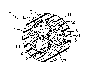
The invention is described with the aid of the drawings, in which Fig. 1 is a
schematic representation of the processing method for making the cable, and Fig. 2
is a sectional view of the cable according to the invention.
DETAILED DESCRIPTION OF THE PREFERRED EMBODIMENT
Fig. 2 details a cable 10 as manufactured according to the invention. Each
transmission unit consists of a buffer tube holding a filling compound 14 and a
plurality of light waveguides 15 loosely disposed in a buffer tube 13. Light
waveguides may be purchased from Corning, Inc. no rod-like strength members are
used. The stranded transmission units are embedded in a matrix 12 consisting of
tensile yarns, such as fiberglass, embedded in a hardened material, which may, for
example, be a urethane acrylate material hardened by the application of ultraviolet
light. An outer extruded plastic tube 11 surrounds and protects the inner cable
elements.
Tensile yarns could also be aramid or carbon fibers, oriented polyethylene, or
small diameter metal wires.
In Fig. 1, transmission units, generally designated as elements 13, and tensile
yarns coated with a hardenable material, the coated yarns referred to as elements
12, are stranded together in a single operation without any requirement for multiple
stranding operations. the tensile yarns may be, for example, fiberglass with a
X Page4

2093593
coating curable by exposure to ultraviolet light. foliowing stranding, the coating is
hardened at apparatus 16, which may be an ultraviolet lamp sold for industrial
applications.
After the tensile yarns and coating are hardened into a matrix, an outer tube
11 is extruded over the stranded transmission units and matrix, so that the matrix
material and embedded yarns occupy the interstices between the transmission units
and outer tube 1 1. Outer tube 1 1 is cooled in water bath 18 and taken up on reel 19.
~; Page 5

Representative Drawing
A single figure which represents the drawing illustrating the invention.
Administrative Status

2024-08-01:As part of the Next Generation Patents (NGP) transition, the Canadian Patents Database (CPD) now contains a more detailed Event History, which replicates the Event Log of our new back-office solution.

Please note that "Inactive:" events refers to events no longer in use in our new back-office solution.

For a clearer understanding of the status of the application/patent presented on this page, the site Disclaimer , as well as the definitions for Patent , Event History , Maintenance Fee  and Payment History  should be consulted.

Event History

Description Date
Inactive: IPC deactivated 2011-07-27
Inactive: First IPC derived 2010-02-01
Inactive: IPC from MCD 2010-02-01
Inactive: First IPC derived 2006-03-11
Time Limit for Reversal Expired 2005-04-07
Letter Sent 2004-04-07
Grant by Issuance 1996-12-03
Application Published (Open to Public Inspection) 1993-10-14
All Requirements for Examination Determined Compliant 1993-04-07
Request for Examination Requirements Determined Compliant 1993-04-07

Abandonment History

There is no abandonment history.

Fee History

Fee Type Anniversary Year Due Date Paid Date
MF (patent, 5th anniv.) - standard 1998-04-07 1998-03-18
MF (patent, 6th anniv.) - standard 1999-04-07 1999-03-24
MF (patent, 7th anniv.) - standard 2000-04-07 2000-03-20
MF (patent, 8th anniv.) - standard 2001-04-09 2001-03-21
MF (patent, 9th anniv.) - standard 2002-04-08 2002-03-20
MF (patent, 10th anniv.) - standard 2003-04-07 2003-03-20
Owners on Record

Note: Records showing the ownership history in alphabetical order.

Current Owners on Record
SIECOR CORPORATION
Past Owners on Record
RICHARD S. WAGMAN
Past Owners that do not appear in the "Owners on Record" listing will appear in other documentation within the application.
Documents

To view selected files, please enter reCAPTCHA code :


To view images, click a link in the Document Description column. To download the documents, select one or more checkboxes in the first column and then click the "Download Selected in PDF format (Zip Archive)" or the "Download Selected as Single PDF" button.

List of published and non-published patent-specific documents on the CPD .

If you have any difficulty accessing content, you can call the Client Service Centre at 1-866-997-1936 or send them an e-mail at CIPO Client Service Centre.


Document
Description 
Date
(yyyy-mm-dd) 
Number of pages   Size of Image (KB) 
Drawings 1996-12-03 1 30
Abstract 1996-12-03 1 15
Cover Page 1996-12-03 1 14
Description 1996-12-03 4 112
Claims 1996-12-03 1 28
Claims 1994-03-31 1 21
Drawings 1994-03-31 1 25
Abstract 1994-03-31 1 14
Description 1994-03-31 3 110
Cover Page 1994-03-31 1 12
Representative drawing 1999-08-05 1 14
Maintenance Fee Notice 2004-06-02 1 173
Fees 1997-03-19 1 39
Fees 1996-03-20 1 90
Fees 1995-04-03 1 33
PCT Correspondence 1996-09-11 1 38