Note: Descriptions are shown in the official language in which they were submitted.
; 20938~
E~::l'ERN~L BONE FIX~TION DEVICE
This invention relates to external bone fixation devices used
in the treatment of bone fractures and more specifically to a
unilateral bone fixation device suitable for use in carrying
out bone transport procedures and also bone lengthening
S procedures.
Gradual bone lengthening by a distraction technique has been
used for some years in order to correct a severe limb-length
discrepancy. In children, limb lengthening has been achieved
by distraction of the growth plate, whilst in adults by
distraction through a defect created in the bone, eg a
transverse osteotomy, where the bone is cut by the surgeon,
and once early bone healing (callus formation) has occurred,
lengthening is achieved by distracting the regenerating bone
tissue (callus).
Various distracting means have been used over the years, the
most commonly used devices being external fixators where each
segment of bone is transfixed by pins or wires attached to
clamps which are then distracted. Examples of external
fixator systems include (i) bilateral frames where fixator
bodies or rods are located one on each side of the bone being
transfixed, (ii) unilateral frames where only a single
fixator body or rod is located to one side of the bone, and
(iii) ring fixators where a series of rings are spatially
arranged around the limbs so as to form a cylinder, the rings
being interconnected by struts.
In acute trauma, or in other conditions, eg tumour resection,
bone infection excision, a section of the defective bone may
be lost. Bone loss may be addressed b~r a procedure known as
bone transport which is based on the same principles as bone
lengthening. In bone lengthening, an external fixator device
ls used to distract two bone fragments away from one another
towards the end of the bone, to thereby lengthen the bone,
whilst in bone transport, the fixator is used to close a bone
defect/gap, this being achieved normally by one fragment of
the defective bone, generally the larger fragment, being
transected, eg by a transverse osteotomy, followed thereafter
`~ 2093828
by distracting the lnner bone fragment of the larger
transected fragment towards the defect rather than towards
the end of the bone which occurs in bone lengthening. The
bone is thereby reconstituted while maintaining the original
bone length.
:.
An alternative method of managing a bone defect and which is
preferred by some surgeons, is to juxtapose the ends of the
defective bone, to thereby shorten same, and thereby promote
early bone healing at the juncture of the bone ends, followed
thereafter by a transection of the larger bone fragment, eg
by a transverse osteotomy, and finally distracting the bone
fragment so as to regain the original bone length. The end
result of this procedure is identical to that described above
but is achieved by different procedural steps. Thus, a
lS surgeon faced with a bone defect may elect to treai same by
either one of these two procedures. With the second
procedure, namely where the original bone length is
shortened, this has usually been a two stage procedure where
the defect is first allowed to heal and the bone is
subsequently lengthened. Each stage may take several months.
It is, however, possible to have the two stages occurring
simultaneously, thereby decreasing the total healing time.
Since the above described two different procedures have in
the past required the use of different fixators this has
necessitated hospitals holding stocks of both - it being left
to the surgeon to elect which procedure is to be performed.
As explained in our earlier patent application PCT/AU91/00036
filed 5th February lY91, it is desirable for an external
fixation device to be able to provide reliable and efficient
dynamisation (both active and passive) in a manner which will
promote fracture healing of the bone. In the case of bone
transport procedures, dynamisation ls preferred at the defect
site and may also be required at the site of lengthening
after the required length is attained.
" ~93~28
The present invention provides further lmprovements and/or
modifications to a fixator of the kind described and
illustrated in our aforesaid PC~ application, which will
render same suitable for both bone transport and bone
lengthening procedures.
It is an object of the present invention to provide an
improved unilateral external bone fixation device which is of
simple construction, of relatively low cost, and which can be
readily adapted for carrying out either bone transport or
bone lengthening procedures.
It is another object of the present invention to provide
improvements to a unilateral external bone fixation device
which are designed so that the device has the ability to
dynamise (axial loading and/or axial motion~, to thereby
promote fracture healing, at the defect site of the defective
bone either prior to bone lengthening of one of the bone
fragments or simultaneously with bone lengthening of one
fragment, or by accelerating bone callus formation, at the
osteotomy site of the defective bone.
It is a further object of the present invention to provide an
improved form of external fixator device which will allow the
rate of lengthening of the bone to be easily and accurately
controlled.
It is a still furt:her object of the present invention to
provide an improved form of bone transport external fixator
which can be easi].y and readily adapted to provide passive
fracture stimulation for immobilised patients and also active
fracture stimulation once the patient is ambulatory.
It is yet a further object of the present invention to
provide an improved form of dynamised external fixation
device which, by virtue of its compactness, will permit early
patient activity and walking, thereby promoting early return
of joint motion and muscle function and strength.
209382~
~roadly according to this invention therefore, an improved
unilateral extern~l bone fixation device having a common
- central longitudinal axis, comprises a central non-rotatable
rigid shaft or rod having a central bore extending
therethrough and being longitudinally displaceable along the
axis of the device, a ~lurality of clamp carrier housings
each having a central passage extending therethrough, said
housings being co-axially supported along the length of the
shaft or rod, the shaft or rod slidably engaging and
extending through the passages of the housings, one of said
housings being ~ixed to the shaft so as to be movable
therewith, each said housing being adapted to support an
orthopaedic pin clamp assembly for removably securing one or
more fixator retainer pins therein, a lead screw or threaded
rod housed within the bore of the shaft or rod and having a
thread mating with a thread in the shaft bore, means at one
end (the proximal end) of said shaft or rod and co-axial
therewith for rotating said lead screw or threaded rod,
arranged and constructed so that rotation of said lead screw,
imparts longitudinal displacement to said shaft, said
displacement simultaneously causing an adjustment in the
axial distance between the confronting ends of said one of
the housings and at least one of said other housings.
More specifically, there are three clamp carrier housings in
co-axially aligne~ relationship, with the intermediate
housing being fixedly secured with the shaft or rod so as to
move therewith, the other two end housings when the device is
being used for bone transport, being held stationary relative
to the lead screw whilst when the device is being used for
bone lengthening, only one (proximal) of the end housings is
held stationary relative to the screw, the other (distal) end
housing being arranged upon rotation of the screw, to move
with the intermediate housing in fixed relationship
therewith. In this description, the proximal end housing is
that which is located adjacent the head end of the lead
screw.
2093828
For bone transport procedures, the lead screw extends the
whole length of the shaft or rod and has its ends journalled
for rotation in respective bearing means supported at
opposite ends of the fixator device, whilst for bone
lengthening, the long lead screw can be replaced by a
relatively short lead screw which projects inwardly from the
proximal end of the shaft by a distance which is less than
the length of the shaft or rod.
Preferably the shaft or rod is polygonally shaped, most
preferably rectangular or square, and has a cylindrical bore
extanding centxally therethrough.
.
Preferably each of the clamp carrier housings has an outer
cylindrical walL and a square or rectangular bore extending
therethrough for snugly receiving the shaft or rod, whilst
each of the pin clamp assemblies has a cylindrical connector
sleeve releasably affixed to a respective said housing, the
connector sleeve when thus released, being rotatable relative
to its respective housing.
In the embodiment of the invention applicable to bone
transport procedure where the original bone length is
maintained, the device comprises a proximal clamp carrier end
housing, an intermediate housing and a distal end housing,
said intermediate housing being fi~edly secured to said shaft
or rod so as to move therewith, each said end housing and
said shaft being axially slidable relative to one another,
the adjusted rotat:ion of the lead screw causing the shaft to
be longitudinally displaced with respect to said end housings
to in turn vary the positions of the end housings relative to
the intermediate housing, the distance, however, between the
two end housings remaining fixed.
In the embodiment of the invention applicable to bone
iengthening procedure where the bone is initially shortened,
the intermediate housing and one of the end housings are held
in fixed relationship and move in unison with the shaft which
is displaced along the lead screw when the latter is rotated,
20~3828
the other of the end housings remainlng stationary with
respect to the lead screw.
According to another aspect of the present invention, the
fixator of thLs .invention can be readily and quickly adapted
to operate in the bone lengthening mode without the need to
replace the long lead screw with the relatively short lead
screw. In this embodiment, the distaL end housing has co-
axially attached thereto removable locking means which is
adaptable so that in a bone transport mode of use, the distal
end housing, during rotation of the screw, remains fixed with
respect to the lead screw, and there~ore at a constant
distance from the proximal end housing, with only the
intermediate housing moving relative to the lead screw,
whilst in a leg lengthening mode of use, the locking means
permits the dist~1 end housing to move, upon rotation of the
lead screw, in unison with the intermediate housing, such
movement being relative to the proximal end housing which
remains stationary with respect to the lead screw. In each
instance, of course, the shaft is displaced longitudinally.
Preferably, the locking means comprises a tubular locking
sleeve threadably engaging the projecting distal end of the
screw, the locking sleeve, when the fixator is in its bone
transport mode of use, being arranged to rotate
simultaneously with the screw, whilst when the fixator is in
its leg lengthening mode of use, the sleeve is loc~ea against
rotational movement and the screw rotates within it.
In a particularly preferred embodiment, the invention
includes actuating means for producing repetitively relative
dynamic axial movement between one or both of the end
housings and the shaft, and in turn relative limited axial
movement between the pin clamp assemblies carried by the
housings, said actuating means being co-axially attached to
one or both ends of said device.
In some instances, relative dynamic axial movement between
the end housings is desirable. The actuating means may
~093828
comprise a co-axially attached DC motor, particularly in the
case where an immobile patient requires bone fracture
exercise or passive stimulation. Alternatively the actuating
means may comprise a calibrated spring axial loading device
S in the case where the patient is ambulatory. In both
instances, the actuating means provides dynamisation (axial
movement or loading) at the defect site (and also at the
osteotomy site) to enhance and promote rapid healing.
It will be appreciated by those skilled in the art that where
the device is being used for bone transport procedures, it is
advantageous to be able to provide for dynamic axial loading
and/or movement at th~ osteotomy site as well as the defect
or docking site. The present invention allows this to be
achieved in a very simple and effective manner, eg by
attaching appropriate removable end fittings to the ends of
the device, which permit limited relative axial movements to
occur between the end housings and the shaf~.
The arrangement of the pin clamp assemblies and the pin
clamps are identical to those described and illustrated in
our aforesaid co-pending PCT application, the contents of
which are incorporated herein by reference.
In order to more fully explain the invention several
embodiments are described hereunder in some further detail
with reference and as illustrated in the accompanying
drawings wherein
Fig 1 is a plan vie~ of an improved fixator device according
to a first embodiment of the invention, applied to a
defective hone of a patient;
Fig 2 is a longitudlnal sectional view taken through the
fixator device shown in Fig 1 (but without the clamp
carriers), wherein the end housings are locked against axial
movement with respect to the lead screw;
~9~28
Fic3 3 is a f.ragmentary sectional view o the device shown in
Fig 2, with the proximal end housing shown in it~ dynamising
mode, wherein it can move axially relative to the shaft,
together with an ax.ial loading fitting for fitment to the
housing;
Fig 4 is a longitudinal sectional view taken through the main
body of a fixator device according to a second embodiment of
the invention;
Fig 5 is a fragmentary perspective view of the intermadiate
lQ clamp carr~er housing ~hown in Figs 2 and 4;
Fig 6 is a fragmentary sectional view of the distal end
housing of the fixator shown in Fig 1, having a modified end
fitting which is shown in the bone transport mode o~ use;
whilst
Fig 7 is a view similar to that of Fig 6 which shows a
further end fitting attached to the distal end of the screw
when the fixator is in its bone lengthening mode of use.
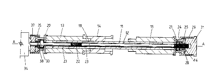
In tha embodiment shown in Figs 1 ana 2, there is shown an
improved external fixator device 10 comprising a rigid,
non-rotating, ~quare or rectangular shaft or rod 11 which is
co-axial with the longitudinal axis "A" of the devi~e lO and
extends longitudinally thereof, the shaft 11 having a
cylindrical bore :12 extending therethrough. The shaft 11
non-rotatably supports a plurality of clamp carrier housings
2S 13, 14 and 15 in co-axial relationship, each having an outer
cylindrical wall and a non-circular bore therethrough. As
shown in Fig 1, the housings 13, 14 and 15 have co-axially
attached thereto adjustable connector sleeves 16, 17, 18
respectively, which in turn support respective orthopaedic
pin clamp assemblies comprising pin clamps in which are
removably secl-red one or more fixator retainar pins, the pins
being inserted into respective fragments of the defective
bone. The connectors, pin clamps and retainer pins are
~J9~32~
essentially in accord with the constructional details
descrlbed in our earlier PCT Applicatlon No PCT/AU91/00036,
and do not form part of the present invention.
In accordance with a feature of the present invention, there
is provided a lead screw 19 which is threadably received
within the bore 12 of the shaft 11 and extends therethrough.
In this embodiment, the lead screw 19 projects from each end
of the device 10 through openings in end plates 20, 21
attached to the outer ends of the housings 13, 15
respectively. The screw 19 has a threaded portion 22 which
threadably engages a threaded portion 23 of the bore 12 at
the proximal end of the shaft 11. The distal end of the lead
screw 19 is also threaded and threadably receives a nut 24
which is housed in a co-axial extension body portion 25 of
housing 15, the body portion 25 being rigidly fixed to the
end of the distal end housing 15 by means of fixing screws
(not shown). The portion 25 has a central passage through
which extends the projecting end of the lead screw 19, the
passage terminating in a small diameter opening 26 which is
sized so that an annular clearance exists between the lead
screw 19 and the peripheral wall of the opening 26. An
axially movable dynamising spacer or bush 28 is slidably
carried on the end of the screw 19 and snugly fits into the
annular clearance. A joining sleeve 29 is slidably retained
on the portion 25 and is internally threade~ for receiving an
end closure cap 31 which, when fully tightened, bears against
the radial end walls of the housing portion 25 and spacer 28
to thereby lock same against axial movement. Thrust washers
are located on eit:her side of the nut 24.
The proximal end of the lead screw 19 has an enlarged head 33
which is keyed to a manually rotatable fitting 34 so that as
the fitting 34 is manually rotated, the lead screw 19 is
rotated simultaneously, rotation of the lead screw in turn
effecting longitudinal to and fro movement of the shaft 11.
The head 33 of the lead screw is housed in an extension
portion 3S of housing 13, the portion 35 being fixedly
mounted to the proximal end housing 13 by securing screws
2093828
(not shown). A knurled collar 37 slidably retained on portion
35, is used to releasably couple the fitting 34 to the end
housing 13. When fully tightened, the fitting 34 bears
against the portion 3S and spacer 38 (identical to spacer 28)
to thereby lock the housing 13 against relative axial
movement with respect to the screw 19.
The intermediate clamp carrier housing 14 is rigidly fixed to
the shaft 11 and moves therewith, whilst each of the housings
13, 15 remain stationary relative to one another upqn
rotation of the screw 19. This arrangement of course allows
the fixator 10 to be used to close a bone defect/gap by
virtue of the movement of the intermediate housing 14 which
has its pins inserted into an inner bone fragment of the
defective bone (refer Fig 1), such movement of the housing 14
towards the housing lS causing the inner bone fragment to be
distracted towards the defect site.
As shown in Fig 5, the intermediate clamp carrier ~ousing 14
can be formed in two halves and simply frictionally clamped
onto the shaft 11 by means of clamping screws 39.
Alternatively the housing can be formed as a unitary moulding
slidably fitted to the shaft 11 and releasably locked
thereto.
Referring to Fig 3, the fixator device is shown with the
proximal end housing 13 in its dynamising mode, the end
fitting 34 having been removed. In this mode, a dynamising
gap eg 1 mm exists between the head end 33 of the screw 19
and the end plate 20 of housing 13. An axial loading unit 40,
similar to that described ln our co-pending PCT Application
~o PCT/AU91/00036, can be threadably attached to the collar
37, with its central stem 40' making pxessure contact against
the head 33 of the screw. A resilient compression spring (not
shown) is housed within the unit 40 which co-acts with the
screw 19 and in turn the shaft 11, to provide an adjustable
spring resistance to bodily axial movement of the housing 13
relative to the shaft 11.
209~82~
In order to dynamise the other end housing 15, end cap 31 i8
removed and replaced by a fitting similar to fitting 40, and
` the dynamisation gap existing between the radially out-turned
flange on spacer 2~ and the radially inwardly directed flange
on the flxed extension portion 25, allows the housing 15 to
undergo the required excursion during either dynamic axial
loading or dynamic axial motion.
Referring to Fig 4 of the drawings, a second embodiment of an
external fixator of this invention is shown, and which
comprises identical clamp carrier housings 13, 14 and 15, and
identical pin clamp assemblies and retainer pins removably
secured therein. However, in this embodiment, the bore 42
which extends through the rectangular rigid shaft 41 has a
threaded end portion at its distal end which threadably
receives a cQnnecting screw 43. The head o~ the screw 43
bears against an inner radial wall of a co-axial, threaded
end fitting 44 which threadably engages nut 45 which in turn
is slidably supported by adaptor 46 secured by fixing screws
to the housing 15. Thus, during distraction, the housing 15
is fixed with respect to the shaft 41, and moves therewith.
During dynamisation, the fitting 44 is removed to allow the
screw 43 and the shaft 41 to move axially together relative
to the housing 15. Normally, a dynamisation gap of
approximately 1 mm is provided, by means of spacer bush 38,
to permit dynamic axial movement of the housing 15.
The lead screw 48 is short relative to the lead screw 19 of
the first embodiment, and is provided with a threaded inner
end portion 49 wh:ich threadably engages a threaded portion of
the bore 42 of the shaft 41, the threaded bore portion being
formed by a drilling and tapping operation. The fittings at
the proximal end of the fixator device are similar to those
described in the first embodiment and co-operate together, so
that when in the loc~ed mode, the housing 13 remains
stationary relative to the screw 48 during rotation thereof.
The intermediate clamp carrier housing 14 is fixedly clamped
to the shaft 41 and is arranged to ~ove therewith; however,
1 1
~0~3828
~he distal end housing 15, in contradistinction to the first
embodiment, is fixed with respect to the shaft 41, the
arrangement being such that upon rotatlon of the lead screw
48, the shaft ~1, along with the housings 14, lS, are
displaced longitudinally in a fixed orientation along the
axis of the device, the housing 13 remainlng stationary.
This mechanism is suitable for carrying out bone treatment
procedure where the defective bone is initially shortened 50
as to close the bone defect, whereafter the larger bone
fragment is transected eg by a transverse osteotomy, and then
distracted to regain the original bone length. In this
instance, the pin clamp assemblies supported by housings 14
and 15 have their retainer pins respectively transfixed to
the inner bone fragment and the outer bone fragment remote
from the closed defect. rhis procedure wilL be readily
understood by those skilled in the art.
Referring now to Fig ~ of the drawings, the fixator of Fig 1
is modified in that the distal end housing 15 is retained on
the projecting end of the lead screw 19 by means of an
elongate locking sleeve 51 which is screwed onto the lead
screw 19 and is rotatably housed within member 25, the sleeve
51 in turn being held in place by a lock nut 52. An annular
manual setting knob 53 is slidably supported on a tail
portion of sleeve 51 and is 'ocked thereon by means of grub
screw 54. An end cap 55 is threadably received within the
threaded bore of collar 29 and closes off the distal end of
the fixator. Fig 6 shows the fixator in a bone transport
mode of use, with the sleeve 51 being locked to the lead
screw 19 by nut 52 and being made to revolve therewith. In
this condition, the position of housing 15 is controlled by
the lead screw 19 and remains fixed with respect thereto.
With the housing 13 also being fixed with respect to the
screw 19, the end to end distance between the housings 13, 15
remains constant with only the axial distance between the
confronting ends of the housings 13, 14, 15 being altered,
due to the movement of housing 14 fast with shaft 11.
2093828
Referring to Fig 7, the connection on the end of the screw 19
is arranged so that the fixator can be used for bone
lengthening without the need to replace the lead screw 19.
This is achieved by removing the end cap 55, the lock nut 52
and also the grub screw 54 (shown in Fig 6). A longer grub
screw 58 is screwed into the knob 53, the grub screw 58
having a projecting outer end portion which locates in a slot
59 formed in the s~irt 60 of end cap 61 which is threadably
connected to collar 29. With screw 58 tightened and the cap
61 fitted, the knob 53 and in turn the sleeve S1 are
prevented from turning as the screw 19 is rotated. As the
pitch on the lead screw 19 is the same at both ends, the
sliding shaft ll together with the intermediate housing 14
and the end housing 15 remain in a fixed orientatio~ and all
move simultaneously relative to the end housing 13 upon
adjusted rotation of the lead screw 19.
In each embodiment, the lengthening of the defective bone in
either of the aforementioned bone transport procedures can be
controlled through a manual screw tightening device or a
motorised device co-axially attached to the proximal end nut
37 to drivir.gly couple with the shaft 11, 35. A manual screw
tightening device enables a surgeon to manually adjust the
rate of distraction, eg 1 mm once daily or in divided
increments, eg 4 .x ~ mm daily, whilst the motorised device
enables a predetermined lengthening rate to be achievad, with
the motor being run continuously or intermittently.
The present invention will allow dynamisation to occur at the
fracture site, either by dynamised axial motion through a co-
axially attached rnotor, eg when a patient is hed bound, or by
dynamic axial loading using a calibrated spring loaded device
(as described in our earlier co-pending PCT application), in
each instance the dynamisation being achieved by repetitive
oscillating movement occurring between the housings 13, 14,
15 and in turn their pin clamp assemblies, such movement
being possible by virtue of the sliding engagement of the
shafts 11, 41 in the bores of the housings 13, 15. For axial
13
~93828
dynamic loading to occur with the fixator sho~n in Fig 4, the
end cap 44 will need to be removed.
A brief aonsideration of the above descrihed embodiments will
indicate that the invention provides an improved form of
external bone fixation device which is especially suited for
carrying out bone transport procedures, although it should be
appreciated that the invention may be adapted for use in
conventional bone lengthening procedures where two bone
fragments are distracted from one another towards the
respective ends of the bone. The fixator of the present
invention is of extremely simple construction and permits
simple and ready attachment of an actuating device for
producing dynamisation at the defect site, in a compact
manner.
14