Language selection

Search

Patent 2094020 Summary

Third-party information liability

Some of the information on this Web page has been provided by external sources. The Government of Canada is not responsible for the accuracy, reliability or currency of the information supplied by external sources. Users wishing to rely upon this information should consult directly with the source of the information. Content provided by external sources is not subject to official languages, privacy and accessibility requirements.

Claims and Abstract availability

Any discrepancies in the text and image of the Claims and Abstract are due to differing posting times. Text of the Claims and Abstract are posted:

  • At the time the application is open to public inspection;
  • At the time of issue of the patent (grant).
(12) Patent Application: (11) CA 2094020
(54) English Title: RING BINDER CARRIER RAIL
(54) French Title: RAIL PORTEUR POUR RELIURE A ANNEAUX
Status: Deemed Abandoned and Beyond the Period of Reinstatement - Pending Response to Notice of Disregarded Communication
Bibliographic Data
(51) International Patent Classification (IPC):
  • B42F 03/04 (2006.01)
  • B42F 13/26 (2006.01)
(72) Inventors :
  • LAW, CHUN CHEUNG (Hong Kong, China)
(73) Owners :
  • WORLD WIDE STATIONERY MFG. CO., LTD.
(71) Applicants :
  • WORLD WIDE STATIONERY MFG. CO., LTD. (Hong Kong, China)
(74) Agent: SMART & BIGGAR LP
(74) Associate agent:
(45) Issued:
(22) Filed Date: 1993-04-14
(41) Open to Public Inspection: 1994-10-15
Examination requested: 1999-05-10
Availability of licence: N/A
Dedicated to the Public: N/A
(25) Language of filing: English

Patent Cooperation Treaty (PCT): No

(30) Application Priority Data: None

Abstracts

English Abstract


ABSTRACT
A carrier rail for a ring binder which is provided with
a plurality of ribs along the longitudinal axis of the rail.


Claims

Note: Claims are shown in the official language in which they were submitted.

THE EMBODIMENTS OF THE INVENTION IN WHICH AN EXCLUSIVE
PROPERTY OR PRIVILEGE IS CLAIMED ARE DEFINED AS FOLLOWS:
1. A carrier rail for a ring binder which is provided with
one or more longitudinal ribs.
2. A rail as claimed in Claim 1 wherein a plurality of
said ribs are provided along the central longitudinal axis of the rail.
3. A rail as claimed in either Claim 1 or 2 wherein said
ribs are of the same length.
4. A rail as claimed in either Claim 1 or 2 wherein said
ribs are of different lengths.
5. A rail as claimed in any preceding claim wherein the
ribs are formed by a pressing function.
6. A rail as claimed in any preceding claim wherein the
rib is provided with a base which is parallel to the rest of the rail.
7. A rail as claimed in any preceding claim wherein at
least one side of the rib is sloped relative to the rest of the rail in the
longitudinal direction.
8. A rail as claimed in any preceding claim wherein at
least one side of the rib is sloped relative to the rest of the rail in the
transverse direction.
9. A rail as claimed in any preceding claim wherein the
rib has four sides which are all sloped relative to the rest of the rail.
10. A rail substantially as herein described with reference
to Figures 2 and 3 of the drawing.
11. A ring binder using a rail as claimed in any preceding

7
claim.
12. A ring binder substantially as herein described with
reference to Figures 1 to 3 of the drawings.

Description

Note: Descriptions are shown in the official language in which they were submitted.


-- 2 ~
IMPROVEME~NTS IN AND RELATING TO A RING BIN~DER
CARRIER RAIL
This invention relates to ring binders which hold paper
and the like for loose-leaf binders, files, folders and the like. ~ :
Carrier rails in prior art ring binders have the
tendency, firstly to be bent when a ring member is attached thereto
during assembly, and secondly to twist excessively along the -
longitudinal axis of the rail when the ring binder is opened and
closed, . ~ -
It is an object of this invention to overcome one or
more of the abovementioned problems. ~
In accordance with the invention, a carrier rail for a ~ :
ring binder is provided with one or more longitudinal ribs.
Such an arrangement is particularly useful, since the
provision of ribs prevents any excessive bending occurring when ring
members are attached to the rail during assembly, and secondly
prevents any or excessive twisting movement along the longitudinal
axis of the rail occurring when the ring binder is actually being .~
opened and closed, thereby allowing for easier closing and opening ~:
of the ring membcrs, since the ring binder is more integral. ; ~
: :
The bending problem prevents easy assembling of ring
binders by machines, and this leads to wastage of rails of at least ~`~
25 17% during the assembly process. It has been found in tests, that
with the provision of ribs, no rails are wasted whatsoever.
Holes may be provided in the rail in order to act as :
' ~ ' '.' ~ ' ' ' :. "' '' ,' ''`' ' ' . . . ' ' . ' .

2 2~9ll~2~
guiding means for the rail during actual assembly of the ring binder,
and the provision of such holes in the rail makes the twisting effect
worse. The provision of the longitudinal ribs on the rail overcomes
this additional twisting problem as well.
Suitably a plurality of ribs are provided along the
longitudinal axis of the rail.
Suitably these ribs can be the same length or different
lengths.
Advantageously the ribs are formed by a pressing
function.
Preferably the rib has a base parallel to the rest of the
rail, at least one side sloped relative to the resti of rail in the
longitudinal direction, and one side sloped relative to the rest of the
rail in the transverse direction. Such has the advantage that the
centre length and width of the rail are effect;vely made longer and
wider due to the indented rlbs when compared to a completely flat
rail, and accordingly the rail has greater stiffness.
The invention will now be described by way of
example with reference to the accompanying drawings in which:
2(1 ~igure I shows a perspective view of a ring binder in
accordance with the invention;
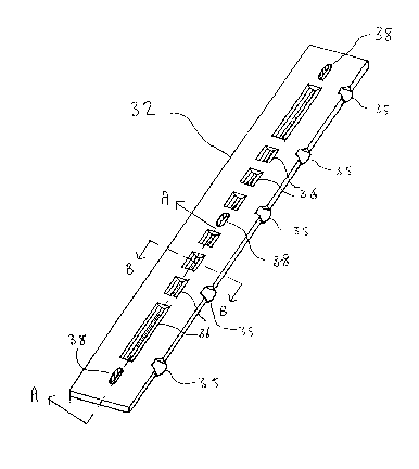
Figure 2 shows a perspective view of the carrier rail
portion of the ring binder shown in Figure 1;
Figure 3 shows a cross-section of the rail of ~igure 2,
. - ,
::.. '' ~ :

3 2 ~ 2 ~
as taken along lines A-A of the rail shown in Figure
2, and
Figure 4 shows a cross-section of the rail of Figure 2,
as taken along lines B-B of the rail shown in Figure 2
S In the drawings a ring binder 10 is shown for a loose-
leaf binder comprising a base member 12, three ring members 14
spaced along the base member (only one of which is shown in Figure
1), and an opening and closing mechanism 20 at each end of the base
member ~again only one of which is shown in Figure 1). The base
member 12 comprises a housing member in the form of an upper
rigid structure 24 which is curved in cross-section and which
supports between its two overlapping sides 26 a pivotable lower
structure 30 comprising two carrier rails 32 pivotable to each other
along the longitudinal axis of the binder 10.
lS The ring members 14 are mounted on the pivotable
lower struc~ure 30 and in particular, one of the ring components (ie
component 14a) of each ring member is mounted on the carrier rail
32 while the other ring component (not shown) of each r;ng member
is mounted on the other carrier rail (also not shown).
Q Fastening means 34, meanwhile, are also provided on
the upper strueture 24 in order to secure the ring binder 10 to a
paper folder or the like.
The two carrier rails 32 are movable (ie pivoted about
lugs 35) relative to each other between a lower position and an upper

-
4 2
position due to the action of the opening and closing mechanism 20
on each end of the carrier rails.
The opening and closing mechanism 20 is pivotably
supported on each end of the upper rigid structure 24 and is in
engagement with each end of the pivotable lower structure 30 in
order to position the opening and closing mechanism 20 between the
upper and lower structures.
The carrier rail 32 is shown in greater detail in ~igure
2, and in particular is shown having a number of longitudinal ribs 36
of varying lengths and each of trough like shape.
It will he noted from Figures 3 and 4, that the ribs 36
are deformed and/or pressed relative the rest of the rail 32 such that
extra stiffness is provided to the rail. In particular, the base of the
ribs 36 is deformed and/or pressed such that it is parallel to the rest
of the rail 32. The ribs 36 are also provided with two sides 42
which are sloped relative to the rest of the rail in the longitudinal
direction, and two sides 44 which are sloped relative to the rest of
the rail in the transverse direction.
: , ~, . -~
Such provides the advantage that it prevents bending
~! ~ .20! of the rail when the ring member 14a is attached to a corresponding
hole 38 provided in the rail during assembly of the ring binder, and ~ ..
~ .. ,.:
also prevents twisting of the rail 32 during opening and closing of the ~ :~
ring members 14 when the ring binder is in actual use.
Regarding twisting of the rail 32, when the ring binder :
; '`''" ~

2 ~ 9 ~ 0 2 ~
is forced open at one end, the rails are twisted under torsion, and if
the rails are not rigid enough to transmit the torsion to the other end
of the binder, the ring members 14 will simply not open. The
provision of ribs 36 effectively increases the longitudinal length of
S the rails thereby increasing the rigidity of the rail.
An particular advantage of providing the ribs is by
increasing the stiffness of the rail, the thickness of the rail can be
minimised thereby saving material. In particular, the thickness of
each rail can be lowered by 0.1 mm.
It has been found in calculations that the torque
increase for the improved rail in the x direction is 1.34% whilst the
torque increase for the rail in respect of the y axis direction is 1.3%.
The total torque increase for the modified rail compared to prior art
arrangements is thus 2.64%, and this is equivalent to a prior art rail
15 with a thickness increased by 1%.
The whole content of the two co-pending patent
applications filed on the same day as this case by the same applicant
are incorporated into this case by reference thereto.

Representative Drawing
A single figure which represents the drawing illustrating the invention.
Administrative Status

2024-08-01:As part of the Next Generation Patents (NGP) transition, the Canadian Patents Database (CPD) now contains a more detailed Event History, which replicates the Event Log of our new back-office solution.

Please note that "Inactive:" events refers to events no longer in use in our new back-office solution.

For a clearer understanding of the status of the application/patent presented on this page, the site Disclaimer , as well as the definitions for Patent , Event History , Maintenance Fee  and Payment History  should be consulted.

Event History

Description Date
Inactive: IPC from MCD 2006-03-11
Application Not Reinstated by Deadline 2003-04-14
Time Limit for Reversal Expired 2003-04-14
Deemed Abandoned - Failure to Respond to Maintenance Fee Notice 2002-04-15
Amendment Received - Voluntary Amendment 1999-12-15
Inactive: Status info is complete as of Log entry date 1999-06-09
Inactive: Application prosecuted on TS as of Log entry date 1999-06-09
Letter Sent 1999-06-09
Request for Examination Requirements Determined Compliant 1999-05-10
All Requirements for Examination Determined Compliant 1999-05-10
Inactive: Adhoc Request Documented 1997-04-14
Deemed Abandoned - Failure to Respond to Maintenance Fee Notice 1997-04-14
Application Published (Open to Public Inspection) 1994-10-15

Abandonment History

Abandonment Date Reason Reinstatement Date
2002-04-15
1997-04-14

Maintenance Fee

The last payment was received on 2001-04-12

Note : If the full payment has not been received on or before the date indicated, a further fee may be required which may be one of the following

  • the reinstatement fee;
  • the late payment fee; or
  • additional fee to reverse deemed expiry.

Patent fees are adjusted on the 1st of January every year. The amounts above are the current amounts if received by December 31 of the current year.
Please refer to the CIPO Patent Fees web page to see all current fee amounts.

Fee History

Fee Type Anniversary Year Due Date Paid Date
MF (application, 5th anniv.) - standard 05 1998-04-14 1998-03-18
MF (application, 6th anniv.) - standard 06 1999-04-14 1999-03-30
Request for examination - standard 1999-05-10
MF (application, 7th anniv.) - standard 07 2000-04-14 2000-03-27
MF (application, 8th anniv.) - standard 08 2001-04-17 2001-04-12
Owners on Record

Note: Records showing the ownership history in alphabetical order.

Current Owners on Record
WORLD WIDE STATIONERY MFG. CO., LTD.
Past Owners on Record
CHUN CHEUNG LAW
Past Owners that do not appear in the "Owners on Record" listing will appear in other documentation within the application.
Documents

To view selected files, please enter reCAPTCHA code :


To view images, click a link in the Document Description column. To download the documents, select one or more checkboxes in the first column and then click the "Download Selected in PDF format (Zip Archive)" or the "Download Selected as Single PDF" button.

List of published and non-published patent-specific documents on the CPD .

If you have any difficulty accessing content, you can call the Client Service Centre at 1-866-997-1936 or send them an e-mail at CIPO Client Service Centre.


Document
Description 
Date
(yyyy-mm-dd) 
Number of pages   Size of Image (KB) 
Representative drawing 1998-08-13 1 10
Description 1995-04-07 5 285
Abstract 1995-04-07 1 35
Drawings 1995-04-07 2 105
Claims 1995-04-07 2 129
Acknowledgement of Request for Examination 1999-06-08 1 179
Courtesy - Abandonment Letter (Maintenance Fee) 2002-05-12 1 183
Fees 1998-03-17 1 43
Fees 2001-04-11 1 31
Fees 1999-03-29 1 34
Fees 2000-03-26 1 30
Fees 1996-04-11 1 35
Fees 1997-03-31 1 31
Fees 1995-03-26 1 62