Note: Descriptions are shown in the official language in which they were submitted.
WO 93.'04420 PCI /US92/07172
2094147
TEMPERATURE CONTROL DEVICE
AND
METHOD OF CALIBRATION
BACKGROUND OF THE INVENTION
1.Field of the Invention
The invention relates generally to fluid-filled heating pads
and more specifically to control circuitry for maintaining a
desired temperaturs of fluid in such fluid-filled heating pads.
2. Brief Description of the Prior Art
Water-filled heating pads are generally used in hospitals
because they are considered to be relatively safe and efficient.
One fluid-filled heating pad currently on the market is sold by
Baxter Healthcare Corporation. This heating pad includes a
3 control module that is connected to a pad by a pair of tubes.
r. Water is heated in the control module and is circulated through
the tubes to the pad. A thermistor located in the control module
monitors the temperature of the fluid within the module.
If the distance between the module and the pad is
relatively short, the temperature in the pad is approximately
2Q equal to the temperature in the module. However, if the
` distance is significant, or if the tubes connecting the pad to the
module are exposed to significant temperature drops, the fluid in
the pad may be siqnificantly lower than the temperature of the
fluid within the module. Therefore, it is desired to provide a
more accurate means of monitoring the temperature of the fluid
in the pad.
. , .
All fluid-filled heating pads in which the fluid is
electronically he~ted require a means of calibrating whatever
.... .. . . ~ . .. - . . :.- .. .. , . . . . . . :.-
WO 93/04420 PCr/llS92/07172
209~147
temperature monitoring device is used. As discussed above,
thermistors that are iocated in a control module have been used
in the past to monitor the temperature of fluid in a remotely
located heating pad. Such thermistors generate a nonlinear
s signal which needs to be calibrated in order to correlate the
thermistor signal to the temperature of the fluid.
Earlier versions of electronically heated fluid-filled pads
using such thermistors were calibrated using one or more
potentiometers. These potentiometers were typically adjusted
0 by a manufacturer during the manufacture of a regulator module
to individually modify the output signal from each thermistor in
order to correlate that thermistor's output signal to a given
temperature range. This meant that each thermistor had to be
manually calibrated during the manufacturing process. More
recently, self-calibrating electronic circuits have been developed
which do not require the manufacturer to calibrate each unit
individually. In a self-calibrating unit, two high-precisions
reference resistors are used to provide a "two-point calibration."
The two reference resistors are used to measure and
20 calibrate the current generator which, in turn, is used to
measure the resistance of the temperature measuring thermistor.
the Measured and calibrated current is applied to the thermistor.
A voltage, caused by the current, is developed across the
thermistor. The voltage across the thermistor is directly pro-
2- portional to the resistance of the thermistor.
The resistance of a thermistor is inversely proportional to
its temperature. Thus as the temperature of the thermistor
decreases, the resistance of the thermistor increases, and as the
temperature of the thermistor increases, the resistance of the
30 thermistor decreases. Accordingly, the resistance of a
thermistor (and through additional calculations its temperature)
can be calculated by dividing the voltage developed across the
.
' " ' :
wo 93/04420 2 ~ 9 4 1 4 7 PCI /US92/07~72
thermistor by the amount of current passing through the
thermistor .
Since the resistance of a thermistor is an indication of the
temperature of the thermistor, and since the resistance a
thermistor (R~herm~to~ ) can be calculated as follows:
R -- Vtherml6tor
therrnl~tor
therml6tor
where
- Vth~mmlctor = the voltage across the thermistor, and
..ol = the current through the thermistor.
; Thus, any error in measuring the current through the resistor
produces an error in determining the temperature of the
thermistor.
While the use of a "two-point" calibration method is an
accurate way of measuring and calibrating the current generator,
a need existed to reduce the complexity of a the circuits and
calculations used in a control module for an fluid-filled heating
pad, yet maintain the necessary precision and overall accuracy
of measuring the temperature of a fluid over the very limited
temperature range of interest using the resistance temperature
20 characteristics of a thermistor. Therefore, it is an object of the
invention to eliminate one of the resistors to reduce the
complexity of the electronic circuitry. It is also an object of the
invention to provide a thermistor in close proximity to the fluid in
the heating pad to be able to more accurately monitor the
temperature of the fluid in the pad.
.,
- -: - . .
. . . :- - :: ~ :, :
~ - ' ' ' " ' : , ' '
- : ., . .. :
- ' . ' ~ . '
WO 93/04420 PCr/US92/07172 -
209~14~ 4
SUMMARY OF T~E INVENTION
A device for heating fluid to be delivered to a fluid-filled
heating pad is described. The device includes a temperature
regulator module, a pad, and a pair of tubes for transporting
s fiuid between the tank and the pad. Each of the tubes includes
first and second ends in which each of the first ends is
connected to the temperature regulator module and each of the
seconds ends is connected to the fluid-filled heating pad so that
fluid may flow between the pad and the regulator module.
~D The regulator module includes: (1 ) a tank containing fluid
to be heated; (2) a pump for pumping fluid in the tank to the
pad; and (3) temperature control circuitry for monitoring and
regulating the temperature of fluid in both the tank and the pad.
The temperature control circuitry comprises: (1~ a
s microprocessor; ~2l heater means for heating fluid in the tank;
(3) a remote thermistor for measuring the temperature of the
fluid at the pad; (4) a constant current generator that generates
a precision current; and (~) a tank thermistor for sensing the
temperature of the fluid in the tank. The remote and tank
2c~ thermistors are connected to the constant current generator.
The temperature control circuitry also includes a high-
precision reference resistor that is also connected to the
constant current generator. The reference resistor generates a
predetermined, high-precision voltage signal. The subject
2s invention involves the recognition that a pseudo-reference point
can be used as one of two points of a "two-point" calibration,
provided that the second point or pseudo-reference point is the
zero resistance, and therefore, the zero voltage point.
The temperature control circuitry further includes a
3c switching network that is connected to the microprocessor. The
purpose of the switching network is to sequentially connect the
precision constant current generator to each of: (1 ) the tank
; ., ~.:
.
- '
WO 9~/04420 2 0 9 ~ 1 4 ~ Pcr/~S92/07172
thermistor; ~2) the remote thermistor; (3) the high-precision
reference resistor; and (4) the remote thermistor and the
rPference resistor in parallel. The switching network sequentially
applies the precision constant current to each of the above
resistor or thermistor elements to produce a voltage output
signal that is proportional to each of the individual resistive
elements.
An analog-to-digital convertor is also provided that is
connected to the voltage output signal to convert the voltage
output signal into a digital output signal. The digital output
signal is then sent to the microprocessor. The microprocessor
uses the digital output signal from each of the reference resistor,
and the tank and remote thermistors to calculate the
temperature of the fluid in the tank and the temperature of the
fluid at the remote thermistor. The temperature of the fluid is
displayed. The microprocessor compares the temperature of
the fluid to a setpoint temperature anb controls the heater
accordingly. If the temperature o~ the fluid is below the setpoint
temperature, the heater is turned on. If the temperature of the
fluid is above the setpoint value, the heater is turned off.
BRIEF DESCRIPTION OF THE DRAWINGS
Fig. 1 is an isometric vie~ of a fluid-filled heating pad;
Fig. 2 is a block diagram of the temperature regulator
module; and
Fig. 3 is a schematic diagram of the block diagram of Fig.
2.
-
- .
.
- - - : :
WO 93/0442~) PCr/U592/07172
2094147
DETAILED DESCRIPTION OF THE PREFERRED
EMBODIMENT
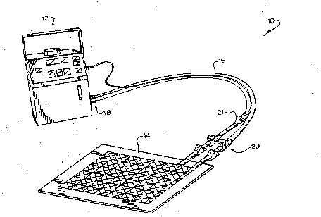
Refer now to Fig. 1 which is a schematic diagram of a
fluid-filled heating pad device 10. The device includes a
s temperature regulator module 12 that is connected to a fluid-
filled heating pad 14 through a pair of tubes 16. One of the
tubes 16 transports fluid to the pad 14 while the other of the
tubes transports fluid from the pad to the regulator module 12.
The tubes each include first and second ends 18, 20
~D respectively. The first end 18 of each tube is connected to the
temperature regulator module 12. The second end 20 of each
tube is connected to the fluid-filled heating pad 14 so that fluid
may circulate between the pad and the regulator module.
In the preferred embodiment of the invention, a remote
thermistor 21 is connected to the second end 20 of one of the
tubes. The remote thermistor 21 senses the temperature of the
fluid in the second end of one of the tubes. Since the second
end of each of the tubes is in close proximity to the fluid-filled
pad 14, the remote thermistor 21 provides an accurate reading
2c of the temperature of the fluid in the pad. Although in the
preferred embodiment of the subject invention, the remote
thermistor is located at the second end of one of the tubes, ir,
other embodiments, the remote thermistor may be actually
located on the pad 14.
2s Refer now to Fig. 2 which is a block diagram of the
temperature regulator module 12. As can be seen in the figure,
the regulator module 12 includes a tank 22 that contains fluid to
be pumped to pad 14. The regulator module 12 also includes a
pump 24 to pump water in the tank through one of the tubes to
30 the pad 14. The module 12 also includes a heater 26 for
heating the fluid in the tank.
WO 93/04420 2 0 9 4 1 ~ ~ PCr/~lS92/07172
The regulator module 12 still further includes temperature
control circuitry 28 for monitoring and maintaining the
temperature of the fluid in the pad 14 at a desired temperature.
The control circuitry 28 includes a microprocessor 30 that is
s connected to the heater means 26. The microprocessor controls
the delivery of current to the heater means 26 and causes the
heater to heat the fluid in the tank 22 to a desired temperature.
The control circuitry 28 also includes a precision constant
current generator 32 which receives a voltage from a precision
c reference voltage source 33. A tank thermistor 34 is also
included in the control circuitry to sense the temperature of the
fluid in the tank. The tank thermistor 34 and remote thermistor
21 are connected to the constant current generator 32 to
receive current from the current generator.
A high-precision reference resistor 38 is also provided in
the temperature control circuitry 28. The reference resistor 38
is also connected to the constant current generator 32 so that
the resistor 38 can generate a predetermined, high-precision
reference voltage signal.
2n The temperature control circuitry 28 still further includes a
switching network 40 that is connected to the microprocessor
30. The microprocessor directs the switching network to
sequentially connect the constant current generator 32 and a
analog-to-digital convertor 42 to the output voltage signals from
25 each of: (1) the remote thermistor 21; (2) the tank thermistor
34; and ~3~ the reference resistor 38. The analog-to-digital
convertor converts the output voltage signals from an analog to
a digital signal which can be transmitted to the microprocessor
30. ;
The microprocessor 30 calculates the temperature of the
fluid in the tank 22 and at the remote pad 14, using the
measured voltage across: (1) the precision reference resistor
. , . ' ,~.
Wo 93/04420 pcr/us92/o7172
2~94~7 8
38, (2~ the tank thermistor 34, and (3) the remote thermistor 21.
The method by which the microprocessor determines the
temperature of the fluid in the tank and pad is set forth in
greater detail below.
s The reference voltage measured across the reference
resistor and the pseudo-reference point (zero volts, zero
resistance) are calculated by the microprocessor and are used to
produce a "pseudo-two-point calibration".
The reference voltat3e, measured across the reference
resistor, minus the pseudo-reference voltage, (zero voltsl,
divided by the resistance of the reference resistor minus the
pseudo-reference resistance, (zero ohmsl, is a measure of the
magnitude of the current generated by the precision constant
current generator. Using this precision current as indicated by
the reference voltage, the ratio of the reference voltage to the
voltage of each of the thermistor elements is used to determine
the temperature of both the tank fluid and fluid in the pad.
The temperature of the water in the tank and the pad is
determined by monitoring the resistance of the tank and remote
thermistors since a thermistor's resistance is proportional to
actual temperature. In the preferred embodiment of the subject
invention, the resistance (R,horm,"or) of each of the tanl; and
remote thermistors is determined by multiplying the known
quantity of the reference resistance (Rre,) by the voltage across
the thsrmistor (V1hO,m,"O,)and dividing the result by the voltage
across the reference resistor (V",). It should be noted that Vro,
is directly proportional to the prscision constant current.
Rre~Vtherml-tOr
R~ho rmi~tor V ro~
The voltage across the reference resisto. minus the
~o pseudo-voltage point, ~zero volts), is proportional to tne
precision constant curre~t. The overall circuit does not need
...-
1 4 1 ~ ~
WO 93/04420 PCr/US92/07172
any adjustment because self calibration is achieved through therecognition that the current through Rth~"m,~tor is the same as R~e~
One of the problems in using a thermistor to measure
temperature is that a method is need to insure that the
s thermistor is properly working. The subject invention provide a
method of discrimina~ion between the out-nf-range high
resistance of a very cold thermistor due to very cold fluid and
the out-or-range high resistance of an open circuit or
disconnected thermistor. This is accomplished by connecting
r the thermistor and the reference resistor to the constant current
generator simultaneously. The two resistances together produce
a parallel resistance circuit within the measurement range.
The voltage ~cross the parallel combination of the resistor
pair is measured and compared to a predetermined threshold
value. If the measured voltage exceeds the predetermined
value, the thermistor is considered to be either open-circuit
disconnected, or otherwise inoperable. By putting the elements
in parallel and measuring the voltage across both elements ~as
opposed to measuring the voltage across the thermistor alone),
2c the dynamic range for open-circuit discrimination versus very
cold fluid is increased.
Refer now to Fig. 3 which is a circuit diagram of the
control circuitry. The precision constant current generator 32
includes operational amplifier 46 and resistors 47-51. Resistors
2. 47, 48, 50 and 51 set the gain of the amplifier 46 while resistor
49 sets the output current of the constant current source. The
switching network 40 includes FET switches 52-54 which
sequentially connect reference resistor 38, remote thermistor 21
and tank thermistor 34 to the constant current generator 32.
3~ The analog-to-digital convertor 42 includes a ten-bit a/d
convertor with an integral analog multiplexer. The data is
transmitted to the microprocessor 30 through serial ports 55-57.
It is important to note that the precision voltage source 33
. .
,
'
' ~' . ' ' ' ~ "
WO 93/04420 PCI/US92/07172
2094~47 10
applies the same voltage to both the constant current generator
32 and the analog to digital convertor 42. This eliminates the
introduction of an error. The voltage is applied to the analog to
digital convertor 42 through buffer 58 and to the constant
current generator 32 through buffer 60. Resistors 58-60 are
used to adjust the voltage of voltage source 33.
While the invention has been described in detail and with
reference to specific embodiments thereof, it will be apparent to
those skilled in the art that various changes and modifications
10 can be made therein without departing from the spirit and scope
of the invention.
'; ; ;
.