Language selection

Search

Patent 2094174 Summary

Third-party information liability

Some of the information on this Web page has been provided by external sources. The Government of Canada is not responsible for the accuracy, reliability or currency of the information supplied by external sources. Users wishing to rely upon this information should consult directly with the source of the information. Content provided by external sources is not subject to official languages, privacy and accessibility requirements.

Claims and Abstract availability

Any discrepancies in the text and image of the Claims and Abstract are due to differing posting times. Text of the Claims and Abstract are posted:

  • At the time the application is open to public inspection;
  • At the time of issue of the patent (grant).
(12) Patent Application: (11) CA 2094174
(54) English Title: MINIATURE HIGH RESOLUTION VIEWSCREEN CANTILEVER I.C.
(54) French Title: CIRCUIT INTEGRE FLEXIBLE MINIATURE POUR ECRAN A HAUTE DEFINITION
Status: Deemed Abandoned and Beyond the Period of Reinstatement - Pending Response to Notice of Disregarded Communication
Bibliographic Data
Abstracts

English Abstract


ABSTRACT
A miniature single
monolithic chip is to be used
to create a viewscreen for
computers, television or
video applications. The image
is formed by the bending of
individual cantilever arms
configured in a two
dimensional array. The
bending is activated with
heat caused by the
application of electricity on
a heating or piezoelectric
element which has been
deposited on the arm.
Advantages of this system
are higher contrast, greater
viewing angle, and capablity
of being reflected onto
another viewing surface.


Claims

Note: Claims are shown in the official language in which they were submitted.

general and specific features
of the invention herein
described, and all
statements of the scope of
the invention which, as a
matter of language, might be
said to fall therebetween.
1. To have invented a
monolithic high density, high
resolution display chip.
2. To have invented an array
of heating elements in this
chip which can be addressed
by matrix.
3. To have each pixel element
change colour of light
reflecting from, or being
passed through miniature
cantilever arms, with
miniature vertical walls
called shutters, fins or other
vertical components whose
angle changes with the
bending of the cantilever
arm.
4. To have made an optical
system with the ability to
enlarge the above mentioned
high resolution image.
CLAIMS:
It is understood that the
following claims are
intended to cover all of the

Description

Note: Descriptions are shown in the official language in which they were submitted.


2~17~
poor display by the bending
of a hi ghl y ref 1 ecti ve
cantilever arm ~hich stops
ref 1 ecti ng 1 i ght by
positioning shutters, fins or
other vertical components,
that are deposited vertically
on the arms, in the way of
the reflective part of the
arm. When the arm i s ~t a
rest the light is reflected
fully between the shutter
~lements and the display is
at i ts bri ghtest. Non-
ref l ecti ng shutters are
mounted vertically on the
arm and do not normally
obstruct the reflection of
light ~s they are very thin.
On the surf ace of the arm
there is a heating element
SPEC I F I CAT I QN usually resistive in nature,
that wh0n heated b~ the
This invention relates to an application of electricity
apparatus and a method for causes the arm to bend. This
producing a display from a bending causes the shutters
single miniature high lncat0d on the arm to
resolution monolithic chip obstruct the light path since
using wafer fabrication type they are now at an angle to
technology. A normal high- that light path while still
contrast type viewscreen being perpendicular to the
(like a cathode ray tube in a bent arm. These arms are
TV),while giving good display very srnall and many are
characteristic's is large ~nd utilized to cons~ruct an
bulky. On the the other hand a image. An image is formedliquid crystal display is very when some of these arms are
portable and narrow but completely bent to their
suf f ers f rom l ow contrast rnaxi mum l i rni t, others are
¦ and poor viewing angle. This bent only a variety of
invention solves the problem distances and others are bent
i ~ of bulky construction and not at all. The tiny arms are
i
;',

2 ~ 7 ~
arranged in rows and a projection type display
columns forming a matrix. where the light source is
posi ti oned behi nd the chi p
Each pixel (or arm) can be and light passes through a
a d d re s s e d b y a p p 1 y i n 9 transl ucent or transparent
electric~ty through the cantilever arm and between
individual wires of the rows the vertical shutters. To
and columns. The cantilver produce ~ black dot the
arms are arranged in a 2 cantilever arm bends and th0
dimensional srray and can shutters cut off the light.
produce a miniature screen This h~s simular advantages
which can be magnified in an as to the above LCD and other
apparatus to produce a much projection type displays.
larger imoge for viewing.
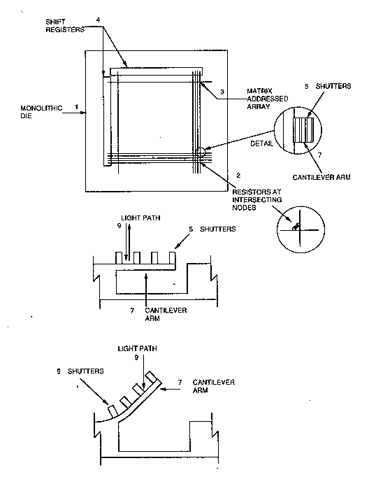
Two intergrated circuits DRAWINGS
might even be used and
magnified for each eye to Reference is first made to
produce 2 ~ 3 dimensional Fig. 1 which illustrates the
affects. The advantage of basic layout of the apparatus
this over a LCD type in accordance with the
magnified image (ie: virtual invention. The monolithic die
reality type goggle or other (1) is shown to consist of an
apparatus) are that the array of heating or resistor
intergrated circuit of this elements layed out on
invention will be much cantilever arms (2). These
cheaper to produce since it resistors would be matrix
can be mass produced using addressed (3) by means of
waf0r fabrication type shift resistors (4). The
technology, while LCD must cantilever arms (7) are
use liquid crystals mounted or etched with
sandwhiched between 2 vertical shutters-~(5). When
panes of transparent the arm is bent (8) the
materi al . shutters (5) are angl ed i nto
the light path (9) thus
This also requires the LCD cutting off the reflection of
display to have a much larger light (6).
sized display pixel while the
pixel size of this invention Fig.2 gives 8 general idea as
can be made much smaller,ie: to the layout of the invention
it is only limited to the as described herein. A lens
re s o l u t i o n o f t h e system ( 1 ) is implemented to
lithographic technology. This magnify the image of the
screen could also be used as
''''.' ,''' " ' ';'' ' . :: ~ ; ~ ,- , " , ~ ' :
' .' ;, , , : ' '.'. : ,

2n~l74
monol i thi c di e (2) thus
creating an im~ginary image.
Fig.3 shows how a projection
is done showing a side view
in which the light source (3)
is going through the
transparent arm ( 1 ) (when
the shutters (4) are not
obstructing the light (3)
and is blocked when the arm
is bent (2).
Fig.4 shows just some of
the possible array
configurations. The top view
(1) shows the cantilever arm
(2) placed over a cavity
(3).Shutters maybe mounted
as shown on top of the arm.
The arm and/or cavity maybe
translucent or transparent
depending on whether it is
being wsed in a projection
type di spl ay. Another
possible configuration shows
how the arms (2~ can be
interwoven. Many patterns
can be formed and are not
limited to these sparticular
schemes.
~. ,:. ~, ;.. .. . . .

Representative Drawing
A single figure which represents the drawing illustrating the invention.
Administrative Status

2024-08-01:As part of the Next Generation Patents (NGP) transition, the Canadian Patents Database (CPD) now contains a more detailed Event History, which replicates the Event Log of our new back-office solution.

Please note that "Inactive:" events refers to events no longer in use in our new back-office solution.

For a clearer understanding of the status of the application/patent presented on this page, the site Disclaimer , as well as the definitions for Patent , Event History , Maintenance Fee  and Payment History  should be consulted.

Event History

Description Date
Inactive: IPC expired 2023-01-01
Inactive: IPC from MCD 2006-03-11
Time Limit for Reversal Expired 1997-04-16
Application Not Reinstated by Deadline 1997-04-16
Deemed Abandoned - Failure to Respond to Maintenance Fee Notice 1996-04-16
Inactive: Adhoc Request Documented 1996-04-16
Application Published (Open to Public Inspection) 1994-10-17

Abandonment History

Abandonment Date Reason Reinstatement Date
1996-04-16
Owners on Record

Note: Records showing the ownership history in alphabetical order.

Current Owners on Record
RAJA SINGH TULI
Past Owners on Record
None
Past Owners that do not appear in the "Owners on Record" listing will appear in other documentation within the application.
Documents

To view selected files, please enter reCAPTCHA code :


To view images, click a link in the Document Description column. To download the documents, select one or more checkboxes in the first column and then click the "Download Selected in PDF format (Zip Archive)" or the "Download Selected as Single PDF" button.

List of published and non-published patent-specific documents on the CPD .

If you have any difficulty accessing content, you can call the Client Service Centre at 1-866-997-1936 or send them an e-mail at CIPO Client Service Centre.


Document
Description 
Date
(yyyy-mm-dd) 
Number of pages   Size of Image (KB) 
Abstract 1994-10-16 1 21
Drawings 1994-10-16 3 121
Claims 1994-10-16 1 45
Descriptions 1994-10-16 3 139
Representative drawing 1998-08-25 1 20
Fees 1995-06-26 1 54