Note: Descriptions are shown in the official language in which they were submitted.
1~861
- 20~8~
EIINGE FOR SHOWE:R STAI~ l)OORS
SPECI FI CAl~ION
Field of t~e Invention
.~
~y present invention relates to a hinge for ~how~x
: 5 ~tall doors and, more particularly, to a hing~e which can allow
.~ ~ree ~winging of a shower stall door or can ble mounted so as to
po~ition ~he shower stall door au~omatically in a ~ixed relativn-
~ ~hip to a door frame, wall or ~he like.
., .
; Back~round of the Invention
~10 A hinge ~or a shower stall can comprise two hinge me~-
bers, one of which has a pair of coaxial hinge sleeves between
~' which the hinge slee~ves o~ the other me~ber is disposed, the
'~ ~leeves ~eing axially aligned and registering with one another
;,- and transversed by a hinge pin or pintl~.
' 15 A hinge of this type is described in EP 02 77 512.
,'. :
~: Between the neighboring sleeves in the space between
,:
.. them, a coil spring which surrounds the hinge pin can be disposed
nd can have its opposite ends affixed to one of the hinge
;,
.; sleeves. As a consequence, when the shower stall door mounted
;~ 20 upon one of the hinge members is swung out o~ a normal rest posi
tion, the spring is stressed and automatically biases the cloor
into its rest position.
. .,
. . .
~;.
.,;,, :
;,,'~ :
~,
'. .: - . .. :
:
'. : ' .
'.. '~ ' ' .' . '~ ~'
18861 ~94~8~
Usual1y, thereXore, the spring operates to c1Ose the
door and, since the hinge is origina11y equipped with the spring
on fabrication, the nor~al rest position into which the spring
urges the door is ~ixed and cannot be a1tered as may be desired
vn mounting of the hinge or mounting of the door. In many cases,
however, it is desirab1e to select the rest position of a sho~er
stall door with respect to the hinge of a structure upon which
the hinge i5 mounted.
Obiects of the Invention
It is therefore an object o~ the present inventioll to
provide an improved hinge, especia11y for a showar stall door,
whereby drawbacks o~ ear1ier hinge structures for similar app1i-
cations are avoided.
Another object o~ tha invention is to provide an im-
proYed hinge which allows, optional1y based upon the mounting of
the hinge, a shower stall door provided with the hinge to swing
fre~ or to be arrested in a predetermined po~ition which may be
se1ected at wi11 by the person mounting the door.
Still another object of the invention is to provicle a
shower ~tall door hinge o~ greater versatility than earlier hing-
e~ ~or this purpose and which, in spite of the increased versa-
tility, is of comparatively 1Ow cost and high functional reli-
ability.
.
~' '
1886~
SummarY of the Invention
~ hese objects and others which will become apparent
her~inafter are attained, in accordance with the invention by
pro~iding the ~wo sleeves of one o~ the members, e.g. that which
i~ affixed to the shower stall door, ~o that their axial spacing
i~ greater than the axial length of the sleeve on the other mem-
ber received between the first mentioned members, and by forming
at least one o~ the coaxial hinge sleeves o~ one of the hinge
~embers with a radial throughgoing bore. The hinge sleeve of a
h~nge sleeve of the other member at at least one o~ it5 ends is
for~ed with a notch while the hinge pin, in the space between two
neighboring sleeves is formed with a radial bore lor a respective
stop pin adapted to drop into the afore~entioned notch or othex-
wise to enga~e therein so that, by gravitational engagement of
the stop pln in the notch a predeter~ined relative angular posi-
tion of the hinge pin and the - ~er provided with the notch is
established, corresponding to the desired rest position of the
~oor.
Utilizin~ the bore provided in the sleeve of the other
~0 member, that sleeve can be anchored to the pin so that a fixed
angular positioning of the pin and the latter member is assured.
As a consequence, the hinge can be utilized a~ a free
swinging hinge for a shower stall door by not connecting the
sleeve provided with the bore with the hinge pin or by omitting
or withdrawing the stop pin from the hinge pin.
.
18861
2 ~ 9 ~ 6
To improve the appearance, in this case, of the hinge,
the axial spacing between the sleeve~ of the two members can be
filled completely or partially by rings or washsrs whose axial
length~ may be equal to half the length of the axial gap between
the sleev~s o~ the two members or equal substantially to half
the differences between the spacing o~ the pair of sleeve~ o~ tha
~irst hinge member and the axial length of the sleeve o~ the
second hinge me~ber.
These rings or washers may be provided at the factory
and may be supplied to the user in place. If, therefore, the
hinge is not to operate as a free swinging hinge but is to posi-
tion the shower stall door at a fixed location, the washers or
rings can be removed and the stop pin inserted in the bore in the
hin~e pin and permitted to ~rop into or engage in the notch~
Once the hinge is in place, the user ean drill through
the bore in the sleeve of the ~irst member into the hinge pin
with the door positioned in its desired rest position relati~e to
the second hinge member, and a position pin then inserted through
this bore and the hole which is made in the hinge pin.
As a consequence, the hinge pin will then be angularly
~ixed to the first hinge member and will rotate therewith, while
the stop pin will engage in the notch when the door i~ in its
desired rest po~ition. The flanks of the notch can be inclined
80 as always to return the door to the rest position regardless
o~ its position into which the door has been swuny, and the
-- 4 --
- . ~ '
18861
~9418B
~lange6 can have transitions into rounded edgss to facilitate the
ca~ing of the pin into the notch.
When the notch is oriented ~o a~ to be upwardly open
and the pin is to drop by gravity into the notch, upon ~winging
of the door from the rest position, a flange o~ the notch will
ca~ the stop pin upw~rdly and, upon release of tha door, the pin
will glide back into the notch/ returning to its re~t position.
On optical grounds, it is advantageous to provide a
washer or ring which fills part of the gap between axially
~ligned sleeves of the two hinge members and formed with a radial
~lit ~or partly accommodating the stop pin engaged in the bore of
the pintle.
The remaining ~pace ~etween neighboring hinge sleeves
i~ to ~e reduced.
~ore particularlyg a hinge of the invention can c4m-
pri~e:
a ~irst hinge member having a pair of axially spaced
apart aligned sleeves;
a second hinge member having a sleeve ali~ned with the
:20 ~leeves of the first hinge member and received therebetween, the
sleeves of the first member being axially spaced by a distance
greater than an axial length of the sleeve of the first member,
one of the members being provided with means for mounting a show-
er ~tall door thereon, the other of the members being provided
~5 with ~eans for mounting the hinge upon a support;
1~8~l 2 0 ~ 6
a pintle extending through tAe sleeves for relative
angular d~splacement of the members about an axis of the pintle;
a radial throughbore ~ormed in at least one sleeve o~
one of the me~bers ~nabling anchoring of the pintle angularly
5 thereto:
a notch for~ed in an end of one of the sleeves opening
~nto a space between the sleeves of the members along the pintle: ;
a radial bore for~ed i~ the pintle in the space; and
a ~top pin removably rec~ived in the radial bore in the
pintle an~ projecting radially therefrom to engage by gravity in
the notch and position the hinge members angularly at a predster-
~ined rest position of the door upon swinging of the door from
the rest position~
Brief Desoription o* the Drawin~
15The above and other objects, features and advantages of
my invention will become more readily apparent ~rom ~he following
description, reference being made to the accompanying highly
diagram~atic drawing in whioh:
FIG. 1 is a perspective view of a shower stall door~0 h~nge as supplied;
FIG. 2 is a perspective view of the shower stall hinge
mounted to provide a fixed rest position for the shower stall
door; and
,
:, ,. . :' '
~''
18861
2~g~g~
FIG. 3 is a frag~entary elevational view showing the
prasence of a washer with a radial slit partly accommodating the
pir~.
- Specific Description
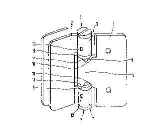
The hinge shown in the drawing comprises two hinge
~embers 1 and 2. The hinge member 1, referred to herein as the
~econ~ hinge member, is provided with a plate 20 having holes 21
allowing the hinge to be mounted on a wall, frame of the sh~wer
~tall or some other support for the hinge and the door.
The other hinge member 2, referred to herein as the
first hinge member can be provided with a pair of plates 22 ~orm-
ing ~eans ~ox mounting a glass door 23 on the hinge.
The hinge ~ember 2 comprises ~ axially spaced apart but
coaxial hinge sleev~s ~, 4. ~he hinge member 1 has a single
hinge sleeve 5 which is disposed between the sleeves 3, 4. ~he
two hinge members 1, 2 are interconnected by a hinge pin 6 or
pintle which passes thxough the axially aligned and registering
hinged sleeves 3, 4, 5. The hinge pin or pintle ~ defines the
~xis of the hin~e about which the glass door 23 can be swung
relative to the wall or frame forming the support upon which the
door is mounted.
The hinge pin 6 can be removed and, for this purpose,
comprises at one end an annular flange 7 or head, while its oppo-
site end is provided with a screw thxead ~not shown) in which a
-, ~ , : . ., ''; '' '.:
,, ,~,
18~61
~crew 8 can be engaged. The screw 8 having a slot 24 in its head
25 which forms a stop for t~e upper end of the sleeve 3. The
~lange 7 ~orms a stop ~or the lower end of the sleeve 4.
The sleeve~ 3 and 4 are axially spac~d by a distance
5 which i~ greater than the axial length o~ the sleeve 5. The
re~ult is an axial spacing between the sleeves 3, 5 and between
the sleeves 4, 5 which, a~ can be seen in FIG. 1 fox the hinge as
supplied from the ~actory, is ~illed by two rings or washers 9
~1ush with sleeves 3, 4 and o~ the same outer diameter and each
of which has an axial length of half of the di~erence between
the axial spacing of the sleeves 3, 4 and the axial length of the
sleeve 5. ~he washers each provide a clean appearance for the
hinge which can be mounted in the con~iguration of FIG. 1 if the
door 23 is to swing freely and not assume a particular rest posi
tion.
The inte e~iate sleeve 5 has at both of its end~ re-
~pective notches 10, the flanges o~ which diverge from the root
of the notch and are rounded as represented at 11 so that these
~lanks form camming surfaces which cam the pin 14 into the bottom
of the notch as will be described.
The two outer coaxial sleeves 4 have respective radial
throughbores 12.
In an axi~l gap or space between the sleeves o~ the two
members, the pintle 6 has a radial throughgoing bore 13 in which'
the stop pin 14 is received or receivable (removably) so that it
can project radially and engage in one of the notches 10. While
8 --
~; ~
',
~, ; ' . - ' :
18861
2~9~6
only one notch is shown at each end of the sleeve 5 in FIG. 1, it
will be understood that each of these notches can represent a
pair of diametrically opposite notches so tha* the pin 14 can
project radially from oppo~ite sides of the pintle 6 and e~gage
in a respectiYe pair of diametrically opposite notches.
If the shower stall dour 23 is tQ be arrested at a
given angular position relativ2 to the support (and to the hinge
~ember 1), the pintle 6 is initially removed and the washers 9
extracted.
In the radial bore 13 of the pintle, the stop pin 14 is
~nserted and the pintle 6 is rotated so that the pin 14 will
engage in the notch 10 of the intermediate sleeve 5. Then the
door is swung with its hinge me~er 2 into the desired rest posi-
tion to which it will in the fll~ule return when released.
With a drill, radial bores are pierced in the pintle 6
through one or both of the throughbores 1~ o~ the sleeves 3, 4
and locking pins are then inserted through the bores 12 to angu-
larly lock the pintle 6 with the sleeves 3, 4.
If the shower stall door i~ then swung out of its rest
.:20 position, the pintle 6 is rotated with the hinge member 2 and
: entrainers the pin 14.
When the pin 14 engages in the upper no~ches of the
sleeve 5 gravitationally, the swinging of the shower stall door
re~ult~ in a camming o~ the pin 14 upwardly. When the door is
released, the pin 14 falls by the weight of the door into the
~otch, thereby swinging the do~r back into its rest position.
_ g _
. - .;:, -
: . . .
':, ,; ; ',. ' ,'.' ~'.,:"'" :," ''
18861
2~9~86
By having notches 10 at both ends o~ the inter~diate
sleeve 5 and enabling the pintle to be inserted either from the
bottom or from the top into the hinge, I am able to provide the
hinge ~or both left and right mounting of the cloor.
A~ can be seen from FIG. 3, a washer ~6 wi~h a radial
510t 27 in which ~he pin 14 is partly engaged, can be provided in
the space between the sleeves o~ the two mem~ers. The axial
length of this washer can be ~; ?n~ioned so that the pin 14 can
nevertheless engage in the notch. The washer reduces the visible
space b tween the sleeves.
- 10 -
~ ,
.
.
.