Language selection

Search

Patent 2094216 Summary

Third-party information liability

Some of the information on this Web page has been provided by external sources. The Government of Canada is not responsible for the accuracy, reliability or currency of the information supplied by external sources. Users wishing to rely upon this information should consult directly with the source of the information. Content provided by external sources is not subject to official languages, privacy and accessibility requirements.

Claims and Abstract availability

Any discrepancies in the text and image of the Claims and Abstract are due to differing posting times. Text of the Claims and Abstract are posted:

  • At the time the application is open to public inspection;
  • At the time of issue of the patent (grant).
(12) Patent Application: (11) CA 2094216
(54) English Title: WINDOW SUPPORT DEVICE IN A MOTOR VEHICLE WINDOW WINDER AND WINDOW LIFTING MEANS INCLUDING THIS DEVICE
(54) French Title: SUPPORT DES GLACES D'UNE VOITURE; DISPOSITIF D'OUVERTURE/FERMETURE DES GLACES COMPORTANT CE SUPPORT
Status: Deemed Abandoned and Beyond the Period of Reinstatement - Pending Response to Notice of Disregarded Communication
Bibliographic Data
(51) International Patent Classification (IPC):
  • B60J 1/20 (2006.01)
  • E05F 11/44 (2006.01)
(72) Inventors :
  • CARDINE, PATRICE (France)
  • CARDINE, PATRICE (France)
(73) Owners :
  • ROCKWELL AUTOMOTIVE BODY SYSTEMS - FRANCE
(71) Applicants :
  • ROCKWELL AUTOMOTIVE BODY SYSTEMS - FRANCE (France)
(74) Agent: PASCAL & ASSOCIATES
(74) Associate agent:
(45) Issued:
(22) Filed Date: 1993-04-16
(41) Open to Public Inspection: 1993-10-23
Availability of licence: N/A
Dedicated to the Public: N/A
(25) Language of filing: English

Patent Cooperation Treaty (PCT): No

(30) Application Priority Data:
Application No. Country/Territory Date
92 04 926 (France) 1992-04-22

Abstracts

English Abstract


ABSTRACT
This device comprises arms (1, 2) arranged in X
configuration, a shaped rail (11) inside which there are
mounted rollers (5, 6) to which are articulated the ends
of the arms (1, 2), one (6) of the rollers being provided
with means for blocking in the rail whilst the other
roller (5) can slide in the latter; the means for block-
ing the said roller (6) comprise an elastic clamp (13)
with two branches (14) shaped so as to be able to cap the
opposite ends of the roller, and through-holes for these
branches are made in the walls of the rail so that the
said branches pass through the rail from one side to the
other, clamping the roller between them. This clamp is
easy to install and can be fitted to existing rollers,
which avoids the use of special components and therefore
decreases the manufacturing costs of the device.


Claims

Note: Claims are shown in the official language in which they were submitted.

- 5 -
CLAIMS
1. Window support device in a vehicle window winder
of the type comprising arms (1, 2) arranged in X
configuration, this device comprising a shaped rail (11)
inside which there are mounted rollers (5, 6) to which
are articulated the ends of the arms (1, 2), one (6) of
the rollers being provided with means for translational
blocking in the rail whilst the other roller (5) can
slide in the latter, characterised in that the means for
blocking the said roller (63 comprise an elastic clamp
(13) with two branches (14) shaped so as to be able to
cap the opposite ends (6a) of the roller, and through-
holes (17, 18) for these branches are made in the walls
(11a, 11b) of the rail so that the said branches pass
through the rail from one side to the other, clamping the
roller between them.
2. Device according to Claim 1, characterised in
that the opposing faces of the branches (14) of the clamp
(13) have cutouts (16) made in them which are conjugate
with rounded surfaces (6a) of the ends of the roller (6).
3. Vehicle window winder of the type with arms (1,
2) arranged in X configuration and whose ends are articu-
lated on rollers (5, 6) mounted in a shaped rail (11)
supporting the window (12), characterised in that it
comprises a device in accordance with one of Claims 1 and
2.

Description

Note: Descriptions are shown in the official language in which they were submitted.


2094216
The subject of the present invention is a window
support de~ice in a vehicle window winder, as well as the
window winder ccmprising this device.
French Patent 87 05 638 (2,614,355) describes a
motor vehicle window winder of the type comprising arms
arranged in X configuration one of which is driving and
the other is driven. The upper ends of the two arms are
associated with a window support device which comprises
a horizontal shaped rail inside which there are mounted
rollers to which are articulated the ends of the arms,
one of the rollers being provided with means for trans-
lational blocking in the rail whilst the other roller can
slide in the latter. Tne sliding roller is articulated ~o
the driving arm, whilst the stationary roller is articu-
lated to the driven arm.
The roller associated with the driven arm isfastened to the rail or slide in order to be able to
cover a tra~ectory parallel to tha~ of the window during
the manoeuvres of actuating the window winder, this
blocking system being called a ~guiding point~ blocking
system.
In order securely to fasten the roller and the
rail, use is generally made of specific components which
do not always have the desired degrees of freedom,
corresponding to an articulation on a ~oint. A device is
thus known in which the component housed in the rail is
pierced with an eyelet in which there is engaged a
blocking screw passing through a corresponding tapped
hole in the slide.
Another drawback of these known devices consists
in the fact that they require a rail whose width is
greater than that required for the displacement of the
sliding roller in order to allow screwing, which is, in
addition, a relatively long operation. The need for using
specially shaped components in order to fasten them to
the shaped rail, instead of the existing standard
rollers, thus leads to a not inconsiderable cost
increase.

203~216
.
The object of the invention is to provide a
window support device by virtue of which these drawbacks
are avoided.
In accordance with the invention, the window
support device is characterised in that the means for
bloc~ing the roller comprise an elastic clamp with two
branches shaped so as to be able to cap the opposite ends
of the roller, and through-holes for these branches are
made in the walls of the rail so that the said branches
pass through the rail from one side to the other,
clamping the roller between them.
This elastic clamp forming a clip is easy to
install in order translationally to block the existing
roller, which constitutes a standard component which may
therefore be used without difficulty.
The invention will now be described with
reference to the appended drawings which illustrate an
embodiment thereof by way of a non-limiting example.
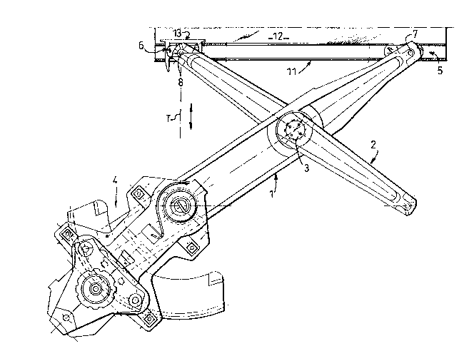
Figure 1 is an elevation of a motor vehicle
window winder of the type envisaged by the invention.
Figure 2 is a partial perspective view on a
larger scale with respect to Fig. 1 of an elastic clamp
and of the shaped rail associated with the latter,
according to an embodiment of the invention.
Figure 3 i~ a horizontal sectional view on a
larger scale of an embodiment of the roller and of its
corresponding blocking clamp in the window support rail.
The device represented in Fig. 1 is a window
winder mechanism comprising two arms 1, 2 arranged in X
configuration and articulated about a common pin 3, as
well as a device 4 for rotationally actuating the arm 1,
this arm therefore being driving whilst the arm 2 is
driven.
Such a window winder, well known per se, is
described, for example, in French Patent 87 05 628
(2,614,355) and therefore does not require a detailed
description.
.

209~216
-- 3 --
The upper ends of the arms 1 and 2 are rotation-
ally articulated on respective rollers or slides 5, 5
about pins 7, 8 carrying ball joints, only the ball joint
9 of the pin 8 of the arm 2 being visible in the drawing.
S The pins 7, 8 and their ball joints are mechanically
securely fastened to the ends of the arms 1 and 2 and may
therefore revolve with respect to the rollers 5, 6 during
the angular displacements of the arms 1 and 2.
The rollers S, 6 are similar and mounted inside
a shaped rail 11 forming a slide, which supports, in a
manner known per se, the window 12. The window winder and
window 12 assembly is housed in a door, not shown.
The roller 6 associated with the upper half-arm
of the driven arm 2 is translationaliy blocked in the
rail 11, in order to cover a vertical tra~ectory T
parallel to that of the window during the manoeuvres of
the window winder, thereby constituting what is
conventionally called a "guiding point . To this end, the
roller 6 is blocked in the rail 11 by means of an elastic
clamp 13 or clip, comprising two parallel branches 14
connected by a base 15. The opposing faces of the
branches 14 each have a cutout 16 whose concavity is
conjugate with the convexity of the ends 6a of the roller
6 in order to be able to cap the latter. Through-holes of
the branches 14 are made in the walls lla and llb of the
rail 11. Two holes 17 are thus formed in the wall lla and
two holes 18 in the wall llb, opposite the holes 17, so
that the branches 14 may pass through the rail 11 from
one side to the other, elastically clamping the roller 6
between them.
The holes 17 are wider than the holes 18 in order
to allow the passage of the median parts of the branches
14, which are wider than their ends which alone penetrate
into the openings 18.
The roller 6 i~ thus effectively translationally
blocked in the rail 11 and may be installed very easily.
The elasticity of the branches 14 advantageously makes it
possible to limit clearances and noise. The clamp 13

2094216
-- 4 --
further exhibits the advantage, compared with the
blockin~ means used to date, of allowing the use of the
e~isting roller 6 with its ball ~oint 9, without
modification, consequently avoiding replacing it with a
special component. This substantially decreases the
manufac~uring cost of the blocking device.

Representative Drawing
A single figure which represents the drawing illustrating the invention.
Administrative Status

2024-08-01:As part of the Next Generation Patents (NGP) transition, the Canadian Patents Database (CPD) now contains a more detailed Event History, which replicates the Event Log of our new back-office solution.

Please note that "Inactive:" events refers to events no longer in use in our new back-office solution.

For a clearer understanding of the status of the application/patent presented on this page, the site Disclaimer , as well as the definitions for Patent , Event History , Maintenance Fee  and Payment History  should be consulted.

Event History

Description Date
Inactive: IPC from MCD 2006-03-11
Time Limit for Reversal Expired 1995-10-16
Application Not Reinstated by Deadline 1995-10-16
Deemed Abandoned - Failure to Respond to Maintenance Fee Notice 1995-04-17
Inactive: Adhoc Request Documented 1995-04-17
Application Published (Open to Public Inspection) 1993-10-23

Abandonment History

Abandonment Date Reason Reinstatement Date
1995-04-17
Owners on Record

Note: Records showing the ownership history in alphabetical order.

Current Owners on Record
ROCKWELL AUTOMOTIVE BODY SYSTEMS - FRANCE
Past Owners on Record
PATRICE CARDINE
Past Owners that do not appear in the "Owners on Record" listing will appear in other documentation within the application.
Documents

To view selected files, please enter reCAPTCHA code :


To view images, click a link in the Document Description column. To download the documents, select one or more checkboxes in the first column and then click the "Download Selected in PDF format (Zip Archive)" or the "Download Selected as Single PDF" button.

List of published and non-published patent-specific documents on the CPD .

If you have any difficulty accessing content, you can call the Client Service Centre at 1-866-997-1936 or send them an e-mail at CIPO Client Service Centre.


Document
Description 
Date
(yyyy-mm-dd) 
Number of pages   Size of Image (KB) 
Abstract 1993-10-22 1 18
Drawings 1993-10-22 2 47
Claims 1993-10-22 1 28
Descriptions 1993-10-22 4 130
Representative drawing 1999-04-05 1 28