Note: Descriptions are shown in the official language in which they were submitted.
VENTED BAh& VALVE AITH I10CK-OUT RING
BACKGROUND OF THE INVENTION
FIELD OF THE INVENTION
The present invention relates to a novel valve stem and
valve member arrangement to provide a method of venting a plastic
ball valve, and provides a lockout ring which can be used With
the ball valve of the present invention as well as with other
types of valves.
The vented valve assembly of the present invention includes
a valve body having a vent hole therein, and first and second
flow-through ends with a valve member receiving chamber
thereinbetween, and a stem receiving passage communicating with
the chamber. A valve member is disposed within the chamber. The
valve member has a throughbore therein in operable alignment with
the first end second flout-through ends and at least one valve
member vent hole through the wall of the valve member in flow
communication with the throughbore. A stem extends through and
is rotatably mounted within the stem receiving passage and
engageable with the valve member for rotating the valve member in
and out of flow-through alignment. A venting means in
cooperation with said stem provides selected flow communication
with the atmosphere through the valve body vent hole, between the
stem and stem receiving passage, through the chamber, and through
said valve body vent hole to the flow-through ends.
1
DESCRIPTION OF THE PRIOR ART
Typical ball valves utilize a ball as the sealing element
which is in alignment with the axis of the stem and free to move
axially. Pressure differential across the valve forces the ball
in the closed position against the downstream seat and the seat
against the body. In fixed ball valves, the ball rotates on stem
extensions, with the bearings sealed with 0-rings. Plastic seats
may be compressed or spring-loaded against the ball and the body
by the assembly of the valves, or they may be forced against the
ball by pressure across~the valve acting against 0-rings which
seal between the seat and the body.
The Clean Air Act of 1990 limits toxic air pollutants.
grouped under Title III, and OSHA regulations set forth in 40 CFR
1910 of 1992 lists chemicals that can effect the environment,
and/or cause worker's personal injury if they leak or are
mishandled. Because of their nature and volume in the process
industries, especially in severe service, valves are a major
target for controlling emissions. In addition, 40 CFR 1910 calls
for various valve lock and interlock systems.
Compliance with these recent OSHA regulations require that
during maintenance on a fluid "air" transfer system, the valve
must seal the line, vent gases downstream, and be locked out.
Assemblies have been devised to successfully accomplish this task
using metal ball valves by using a split-body type of ball valve.
2
2~9~~~ ~'~
The ball can be shaped to allow air from the downstream flow to
seep between the ball and seat and out of a vent hole in the
valve body when the valve is in the closed position. When the
valve is in the open position the ball surface effectively closes
the valve body vent hole. However, this split body arrangement
is limited to use for venting metal ball valves, for the seat
must be compressed very tightly between the ball and housing on
the upstream side of the valve to prevent leakage. A metal ball
in combination with a metal housing and/or metal seat can be
used; however, valves having the components made of plastic are
susceptible to deformation of the plastic upon tightening the
ball against the seat or housing. This limitation limits the use
and effectiveness of vented plastic ball valves constructed in
the same manner as vented metal ball valves.
The venting means described herein can be used for venting
most any type of metal or plastic ball or plug type valve. The
plastic ball valve described herein has a dropout type of valve
body so that the valve may be removed from a piping system for
repair or replacement and provides a good seal using a minimum
number of molded parts made of plastic materials, such as
polyvinyl chloride and the like.
The vented ball valve of the present invention also utilizes
a novel lock-out ring device as a safety device. Various lock-
out devices are known in the art. These prior art devices
generally are comprised of several parts, mechanically linked
3
~~~~~~~J
together. For instance, one type of lock-out device requires
that the lock-out must be slipped onto the valve handle, aligned
with respect to the handle and pipe, then squeezed together so
that the shackle of a padlock can be insert therethrough.
Another type of lock-out device known in the art requires that a
pronged device completely encapsulate the valve body and handle,
adjusted, aligned, and shackled thereon. Still other lock-out
devices consist of a hinged donut type of device which completely
enclosed the valve. However, these devices are not particularly
suitable for use with the vented ball valve of the present
invention, for none of the lock-out devices permit high
visibility of valve handle and body, and a low profile which does
interfere with the vented stream.
The.lock-out rings of the present invention are comprised of
a simple one piece design, which are easy to install and
inexpensive to manufacture. The "d-shaped" ring is placed
coaxially around a pipe and the "leg" member having a hole
therein projects outward from the ring body to facilitate
alignment with a hole in the handle of the ball valve which
accommodates the shackle of a padlock.
SUMMARY OF THE II1VENTIOIB
The vented valve assembly of present invention includes a
valve body having a vent hole therein, and first and second flow-
through ends with a valve member receiving chamber
4
thereinbetween, and a stem receiving passage communicating with
the chamber. A valve member is disposed within the chamber. The
valve member has a throughbore therein in operable alignment with
the first end second flow-through ends and at least one valve
member vent hole through the wall of the valve member in flow
communication with the throughbore. A stem extends through and
is rotatably mounted within the stem receiving passage and
engageable with the valve member for rotating the valve member in
and out of flow-through alignment. A venting means in
LO cooperation with said stem provides selected flow communication
with the atmosphere through the valve body vent hole, between the
stem and stem receiving passage, through the chamber, and through
said valve body vent hole to the flow-through ends.
The~atmospheric venting means includes a generally axial
groove including at least one offset arched portion around about
a portion of its circumference. The axial groove and offset have
an annular sealing member disposed therein forming a seal between
the stem and stem receiving passage. The offset arched portion
and annular sealing member therein are rotatably aligned so that
rotation of the stem rotates the valve member out of operable
alignment with the first and second flow-through ends, and
positions the offset arched portion and annular sealing member
therein in sealing engagement with the stem receiving passage
above the valve body vent hole. Venting flow communication is
provided from the valve flow-through end, through the valve
member vent hole, between the stem and the stem receiving
5
~~~~~~'~e~9
passage, and through the valve body vent hole to the atmosphere.
Rotation of the valve member to the selected flow-through
alignment by rotation of the stem positions the offset arched
portion and annular sealing member therein in sealing engagement
with the stem receiving passage below the valve body vent hole
sealing the stem receiving passage from the atmosphere.
More particularly, the ball valve of the present invention
includes a pair of end connectors detachably held respectively
against a tubular valve body having a valve member receiving
chamber between the first and second flow-through ends providing
a flow passage therethrough, and a stem receiving passage or
bonnet extending upward from and communicating with the valve
member receiving chamber. A seal carrier retaining a seal'member
5 is slidably mounted in at least one end of the valve body seating
a rotatable valve ball actuated by a handle detachably engaging a
valve stem exteriorly of the body. The valve stem has a
generally axial groove including an offset arched portion around
a portion of the circumference and an annular sealing member such
10 as an O-ring seated within the axial groove and offset. The stem
is rotatably secured within a bore or stem receiving passage
extending through the valve bonnet which is an integral part of
the valve body. The valve ball is positioned within the valve
member receiving chamber and held in contact with an annular seal
carried by the carrier and the valve body. The carrier and
annular seal thereon are held in limited radial centering
movement by a retainer ring detachably engaging the valve body
6
~~~tf3t1
sealing ring and providing for a tightening adjustment of the
parts of the assembly when wear occurs upon the seals. A pair of
threaded union nuts serve to join the connectors detachably to
the valve body by threadably engaging with external threads on
the ends of the valve body. A detachable handle engages the
dfstal end of the valve stem and serves to rotate the ball valve
in operable alignment between its open flow permitting and closed
flow blocking positions.
The ball valve includes a dovetail slot into which a
correspondingly shaped key on the lower end of the valve stem is
detachably engaged having a stem mounted within a stem receiving
passage or bore extending laterally from the portion of the valve
body forming a collar or bonnet. The valve ball includes a vent
hole in selectable fluid communication with a sealable passage
between the stem and the stem receiving passage and a vent hole
in the valve body.
In the valve open position, the main flow passage of the
valve ball is aligned with the passage in the valve body, and the
ball vent hole is sealed against the side wall of the valve body
and between the annular seals seating the valve ball. The
annular sealing member or o-ring seated within the axial groove
around the circumference of the stem is biased against the stem
receivng passage and forms an air and water tight seal between
the stem and the stem receiving passage of the valve body below
the vent hole in the valve bonnet to prevent the escape of vapor
7
~~~!~~~e
or fluid from the valve body during use. Rotation of the handle
to the valve closed position, rotates the stem and valve ball so
that the ball vent hole is open to vent the downstream fluid flow
through the ball vent hole in the valve ball to the throughbore
and into the chamber upward between the annular seals seating the
ball and the valve body, and between the lower portion of the
stem and the stem receiving passage of the bonnet. The O-ring
provides a seal between the top portion of the stem attached to
the handle and the lower portion of the stem providing a passage
for the venting of vapor of fluid to the atmosphere or
appropriate container through the vent hole in the valve bonnet
positioned below the offset portion of the O-ring.
The ball valve assembly includes a removable, generally "d"
shaped lock-out ring having a circular main body with a
projection having a hole therein extending therefrom, being
rotatably and coaxially mounted around the valve body positioned
between the stem and union nut, alignable with a hole formed in
the handle when the valve is'in the closed position, whereby a
locking member of a padlock can be inserted through the hole in
the locking ring and the hole in the handle to prevent rotation
of the handle and opening of the valve.
It is an object of the present invention to provide a
venting means for a plastic ball or plug valve to enable the user
to rotate the handle one quarter turn to close the valve and to
8
2~~~~%~
vent vapor or liquid from the downstream flow through the valve
ball, stem, and valve body bonnet vent hole.
It is a further object of the present invention to provide a
inexpensive sealing and venting control mechanism employing an
annular sealing member within an axial groove within the body of
the stem, whereby the groove has at least one offset, upward
extending arch on one side for providing a seal either below or
above the valve body bonnet vent hole depending upon the rotation
of the stem by the handle.
It is an object of the present invention to provide a
reliable lock-out means for a sealed ball valve assembly which
can be installed with the ball valve and readily inserted in or
removed from a piping system without the employment of special
tools.
It is another object of the present invention to provide for
a one piece lock-out ring of~unitary construction.
Moreover it is an object of the invention to provide a lock-
out ring having a thin profile which can be inserted between the
valve body bonnet and flange of a ball valve.
Furthermore, it is an object of the present invention to
provide for a lock-out ring rotatable and coaxial with a pipe or
tubular portion of the valve body.
9
2~~j1~.~~
BRIEF DESCRIPTION OF THE DRAWINGS
A better understanding of the present invention will be had
upon reference to the following description in conjunction with
the accompanying drawings in which like numerals refer to like
parts throughout the several views and wherein:
Figure 1 is a side view of the present invention showing the
vented ball valve and lock-out ring.
Figure 2 is a.perspective view of the vented ball valve and
lock-out ring of Figure 1.
Figure 3 is an exploded perspective view of the vented ball
valve and lock-out ring of Figure 1.
Figure 4 is a longitudinal sectional view of the vented ball
valve and lock-out ring assembly of Figure 1 showing the ball in
the fully open flow position~wherein the flow is from left to
right.
Figure 5 is a longitudinal sectional view of the vented ball
valve and lock-out ring assembly of Figure 1 showing the ball in
the fully closed flow position wherein the flow is from left to
right.
2~9~ ~.
Figure 6 is a transverse sectional downstream end view of
the vented ball valve and lock-out ring assembly of Figure 1 with
the stem and ball valve member positioned in the open valve
position showing the annular sealing member O-ring extending
below the valve body bonnet vent hole sealing the vent, and
showing the ball valve member in the fully open flow position
wherein the flow is from left to right.
Figure 7 is a transverse sectional downstream end view of
the vented ball valve and lock-out ring assembly of Figure 1 with
the stem and ball positioned in the closed valve positio» showing
the arched portion of the axial groove having an O-ring therein
extending above the valve body bonnet vent hole and showing the
ball in the fully open flow position wherein the flow is from
left to right.
Figure 8 is a front plan view of the lock-out ring of Figure
1 of the present invention.
Figure 9 is a side view of the lock-out ring of Figure 8.
Figure 10 is a perspective view of the lock-out ring of
Figure 9, with the hole in the leg member positioned in alignment
with a hole in the handle of the closed valve to be locked out
showing the valve in perspective view in phantom lines.
11
2~~~~r~
Figure 1l is an end view of Figure 1 showing the hole in the
lock-out ring leg member aligned with a hole through the handle
and the vented ball in the closed position, and showing a nipple
extending from the valve valve body bonnet vent.
Figure 12 is an end view of Figure 1l showing the hole in
the lock-out ring member aligned with a hole through the handle
of the vented ball valve shown in phantom lines and the
throughbore of the vented ball valve member in the fully open
position.
Figure 13 is an end view of Figure 1 showing the lock-out
ring leg member rotated away from the handle of the vented ball
valve member in the open position, and showing a deflector, member
extending around the valve bonnet vent hole.
Figure 14 is an end view of Figure 11 showing the hole in
the lock-out ring member rotated away from the handle of the
vented ball valve shown in phantom lines.
Figure 15 is a front plan view of another embodiment of the
lock-out ring of Figure 1 having a leg member wherein the distal
end thereof is bent at an angle to provide alignment with a
handle hole in the extending normal to the axis of the tubular
main valve body.
12
Figure 16 is a side view of the lock-out ring of Figure 15
showing the narrow width of the lock-out ring.
Figure 17 is a top view of the lock-out ring of Figure 15.
Figure 18 is a perspective view of the lock-out ring of
Figure 15, with the hole in the leg member positioned in
alignment with a hole in the handle of the closed valve to be
locked out showing the valve in perspective view in phantom
lines.
Figure 19 is a longitudinal sectional view of the vented
ball valve and lock-out ring assembly showing a vent in the valve
body bonnet and a stem having an axial groove having a downward
offset portion including an annular sealing member therein,
wherein the stem and valve ball member is aligned in the flow-
through position wherein the flow is from left to right.
Figure 20 is a longitudinal sectional view of the vented
ball valve and lock-out ring assembly showing a vent in the valve
body bonnet and a stem having an axial groove having a downward
offset portion including an annular sealing member therein,
wherein the stem and valve ball member is aligned out of the
flow-through position wherein the flow is from left to right.
Figure 21 is a transverse sectional downstream end view of
the vented ball valve and lock-out ring assembly with the stem
13
CA 02094443 2002-08-13
and ball valve member positioned in the open valve position
showing the stem having an axial groove with a downward
offset portion containing an annular sealing member 0-ring
extending below the valve body bonnet vent hole sealing the
vent, and showing the ball valve member in l:he fully open
flow position wherein the flow is from left to right.
Figure 22 is a transverse sectional downstream end
view of the vented ball valve and lock-out ring assembly
with the stem and ball_ positioned in the closed valve
position showing an axial groove having a downward offset
portion including an annular sealing member 0-ring therein
extending above the valve body bonnet vent hole and showing
the ball in the fully open flow pos.i.tion wherein the flow
is from left to right.
1$ DESCRIPTION OF THE PREFERRED EMBODIMENT
The present invention describes a mean:> of venting a
plastic ball valve. More particularly, a thermoplastic
ball valve of the end entry type such as is described in
U.S. Patents: 3, 550, 902, 4, 099, 705, 4, 257, 5 ~'S, and
4, 449, 694 .
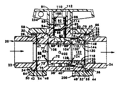
Depicted in Figures 1 and 2 is an end entry vented
ball valve assembly 20 having a lock-out ring 200
constructed in accordance with a preferred embodiment of
the present invention. As illustrated in Figures 3 and 4,
the vented ball valve assembly 20 is adapted for connection
in general longitudinal alignment with a pair of fluid
conduits (not shown), such as pipes, by
l~
means of conventional end connectors 22 and 24. The end
connectors 22, 24 have axial flow passages and provide sockets
adapted to engage the fluid conduits as shown: however, it is
contemplated that the end connectors 22, 24 may be interiorly
threaded to serve as means for attaching pipes. The end
connectors 22, 24 are provided with generally radially outwardly
extending flanges 26 and 28, respectively. Each flange 26, 28
has a substantially radial face 30, 32 and a frustoconical
surface 34, 36 which tapers radially inwardly and away from the
radial face 30, 32.
As best shown in Figures 4 and 5, the vented valve includes
a main tubular valve body portion 38 having a generally
cylindrical external surface 40. The tubular valve body 38
extends from a wall 41 having a first generally radial end face
42 at one end of the body to an annular edge 43 having a second
generally radial end face 44 at the opposite end of the body 38.
An annular retaining groove 45 disposed within the radial outer
end face 42 of the valve body wall 41 contains a resilient
sealing and biasing member such as an end connector O-ring 47
which abuts the radial face 30 of the flange 26 of first end
connector 22 to further assist in sealing of the assembly. Each
end of the external surface 40 of the body 38 is provided with an
externally threaded end portion 46, 48. Union nuts 50, 52
include a threaded cylindrical portions 54, 56 on their inner
surfaces threadably engageable with the threaded end portions 46,
48 of the tubular valve body 38. Extending radially inwardly
CA 02094443 2002-08-13
from one end of the cylindrical threaded portions 54, 56 of
each union nut 50, 52 is a flange 58, 6c~ which presents a
central opening adapted to slide longitudinally on the
outer circumference of the corresponding end connectors 22
and 24, respectively. The union nut flange: 58, 60 include
an internal frustoconical surface 64, 6E> that tapers
radially inwardly and away from the mair: tubular valve body
38 so that it corresponds to the adjacent frustoconical
surfaces 34, 36 of the end connector flanges 26, 28.
Accordingly, when the union nuts 50, 52 are tightened onto
the main valve body portion 38, the radi.a:lly extending
union nut flanges 58, 60 imposes lon~~itt~dinacl forces on the
end connectors .22 and 24.
The open-ended, main tubular valve body 38 is provided
with a longitudinally extending flow passagE~ 68 extending
therethrough from the first generally radial. end face 42
through the wall 41 to the second generally radial end face
44 of the annular edge 43. The flow passage 68 includes a
plurality of axially extending, generally cylindrical
sections of various diameters.
One such section forms an annular receiving recess 69
within an inner radial end face 71 of end wall 41 of the
tubular valve body 38 as illustrated in Figures 4 and 5.
The annular receiving recess 69 includes an axially facing
end wall 73 and a radially facing guide wall 75 for
receiving a first annular support seal member 77,
O
preferably made of TEFLON for seating and :pealing the
valve ball 72 with the tubular valve body 38.
16
Another axial recess positioned generally centrally of the
main valve tubular body 38 defines a valve member receiving
chamber 70. As shown in Figures 3 and 4, the valve member
receiving chamber 70 is essentially the same diameter as the flow
passage 68, wherein at least one end of the main tubular valve
body 38 is sufficiently enlarged for endwise insertion of a valve
member, more particularly a valve ball 72, into the valve member
receiving chamber 70; however, the valve member receiving chamber
may be cylindrically shaped to house a substantially cylindrical
plugged shaped valve member as well.
An axially, inwardly extending counterbore 74 is provided
between the valve member receiving chamber 70 and the end 43 of
the tubular valve body 38. The counterbore n4 aerines an
internal.shoulder 76 spaced apart from the first end 42 of the
main body 38 by a predetermined axial distance having a threaded
inner surface 79 therealong. It is contemplated that another
counterbore 74 structure could be used to replace the wall 41.
however, only one end of the valve body 38 need by open to
accommodate the valve ball member 72.
A bore or stem receiving passage 78 extending downward
through the bonnet 80 defines an axis substantially peYpendicular
to the longitudinal axis of the longitudinal passage 68 through
the tubular valve body 38 communicating with the valve member
receiving chamber 70. The outwardly projecting collar or bonnet
80 formed integral with the main tubular body 38 provides
17
additional lateral support for a substantially cylindrical valve
stem 82 received within the bonnet stem receiving passage 78. A
vent hole 81 is disposed through the valve body bonnet 80 between
the top of the bonnet 80 and the tubular portion of the valve
body 38 for venting vapor and liquid fluids trapped under
pressure in a downstream section of the conduit when the valve is
rotated to the close position. As shown in Figures 1i and 12, a
nipple 65 may extend coaxially around the vent hole 81, or a
deflector 67 may partially enclose the vent hole 81 to provide a
means for directing the flow of the pressurized fluid from the
vent hole 81. A conduit may be attached to the nipple 65 to
direct fluids from the vent hole 81 to a suitable storage
container fox reuse or disposal. The upper end of the bonnet 80
terminates in stepped planes with the upper plane 83 extending
through 270 degrees and the lower plane 85 extending through 90
degrees to form stops 93, 95 against which a handle 91 may abut
when moving the valve into fully opened or fully closed positions
by rotating the handle 91 one quarter turn.
The valve ball member 72 of the preferred embodiment
includes a throughbore 84 therethrough. More particularly, the
valve member 72 of the preferred embodiment as shown best in
Figures 3-5, is a generally spherical valve ball 72 defining a
top wall 55 connected to a bottom wall 57 by a first flow
blocking side wall 59 and a second flow blocking side wall 61,
and a pair of end walls 63 including a central throughbore 84
therethrough defining a flow passage is detachably engageable
18
~~~~~x~~
with the valve stem 82. The valve ball 72 is rotatable about a
rotational axis substantially perpendicular to the axis of the
central bore 84. The generally spherical shape of the ball valve
72 provides a sealing surface in cooperation with the valve body
38. The external surface 86 of the valve ball 72 has a nominal
diameter which is less than the nominal diameter of the valve
member receiving chamber 70 so that the tubular valve body 38
does not interfere with the rotation of the valve ball 72 about
its axis between its "valve open" flow permitting position of
Figures 4 and 6, and the "valve close" flow blocking position of
Figures 5 and 7. As shown in Figures 4 and 5, the stream of flow
through the valve is from left to right; therefore, when the ball
valve member 72 is in the closed position as shown in Figure 4,
rotating the handle 91 one-quarter turn counterclockwise rotates
ball valve member 72 aligning the throughbore 84 with the axis of
the tubular valve body 38 and conduits.
A generally centrally located ball valve member vent hole
102 is disposed through the downstream valve ball side wall,
shown as second ball wall 61 and through the external ball
surface 86 directed toward the downstream end 44 of the tubular
body having the annular edge 43 during the valve closed position.
The portion of the central bore 84 intersecting the external
surface 86 of the ball 72 forms open end side walls defining
central flattened peripheral edges 104, 106 which permit vapor or
liquid fluid entering the central bore 84 from the ball vent hole
102 to flow from the interior of the ball 72 around the
19
peripheral edges 104, 106 upward between the valve stem 82 and
the valve bonnet stem receiving passage 78.
A recess or groove 87 which is generally perpendicular to
both the ball rotational axis and to the bore 84, is provided in
the valve ball 72 at a location where it does not interfere with
the sealing portion of the external ball surface 86. The groove
87 has a dovetail cross-sectional configuration extending
completely across the ball 72 adapted to receive a
correspondingly configured stem end portion. A complementary
stem end portion terminates at its lower end in a key 88 having a
flat lower surface 89 and an arcuate upper surface 90
corresponding generally to the upper surface of the ball at the
point of their engagement as shown in Figures 3 and 7.
The generally cylindrical valve stem 82 is provided with a
generally centrally located, generally hori2ontal axial groove 94
of decreased diameter therein having an offset forming an
upwardly extending arch 96 around a portion of its circumference.
The groove 94 and offset arch include an annular sealing member
98 disposed therein such as a conventional O-ring sealably
engageable with the stem receiving passage 78 of the bonnet 80
forming a vapor and liquid tight seal between the stem 82 and the
stem receiving passage 78 as shown along a longitudinal axis in
Figures 4 and 5, and shown in an end view in Figures 6 and 7. In
this manner a fluid seal is selectively effected between the stem
receiving passage 78 and the valve stem 82 above or below the
2~~~~~~~
bonnet vent hole 81. The upper end of the stem 82 includes
parallel sidewalls 92 and may have at least one ridge 108
extending horizontally outward from the cylindrical portion of
the stem located between the parallel sidewalk 92 to provide a
friction fit with a handle 91.
Figure 4 shows the handle 91 to include a downwardly
extending integral web 110 having a recess 112 (not shown)
therein for receiving the upper end of the valve stem 82. A
shoulder 114 is formed integrally with the web 110 to engage with
the stops 93, 95 of the~bonnet 80 when the assembled handle 91,
valve stem 82, and valve ball 72 are rotated the proper distance.
In the preferred embodiment the handle 91 is simply press fitted
onto the stem 82 so that the ridges 108 of the stem 82 provide a
tight friction fit with the web 110 of the handle 91. A
detachable fastening clip (not shown) may be attached to the web
110 of the handle 91 to provide a shim adapted to cooperate with
the parallel sidewalls 92 to enhance the gripping action of the
between the web 110 of the handle 91 and the upper portion of the
stem 82.
As best shown in Figures 3, 4, and 5, the valve ball 72
detachably engageable with the valve stem 82 and is normally
confined between the first annular support seal member 77 and
a similar second annular support seal member 116 mounted within
a tubular bifurcated seal carrier 118. The seal carrier 118 is
slidably received in the ball entry annular edge end 43 of the
21
main tubular valve body 38 and held adjustably into position by
an adjustable retainer ring member 120 threadedly engaged with
the threaded inner surface 79 of the tubular body 38.
The seal carrier 118 includes a longitudinal bore 122 having
a diameter substantially equivalent to the diameter of the valve
ball 72 throughbore so that the fluid passing through the tubular
valve body portion 38 is substantially unrestricted by the
presence of the seal carrier 118 and valve ball 72. The leading
end of the seal is provided with an annular receiving recess 124
which includes an axiahly facing end wall 126 and a radially
facing guide wall 128 for receiving the second annular support
seal member 116, preferably made of teflon for seating and
sealing the valve ball 72 within the tubular valve body 38.
The seal member 116 is dimensioned for limited radial centering
movement in the receiving recess 124.
The leading end of the seal carrier 118 has a larger
external diameter and the trailing portion 130 has a smaller
external diameter to define a shoulder 132. The external
diameter of the trailing portion 130 of the seal carrier 118 is
less than the interior diameter of the bore 134 of the retainer
ring 120 permitting a coaxial fit of the retainer ring 120 around
the trailing portion 130 so that the retainer ring slidably abuts
the shoulder 132 of the seal carrier 120. The exterior diameter
136 of the retainer ring 120 is threaded and sized according to
the diameter of the threaded inner surface 79,of the tubular
22
CA 02094443 2002-08-13
valve body 38 for threadedly engagement therein. The
retainer ring 118 provides for axial movement of the seal
carrier 118 against the valve ball 72 for adjustment within
the tubular body 38.
S The seal carrier 118 is provided with a
circumferential groove 138 that receives a peripheral seal
member 140 such as an 0-ring to prevent fluid from leaking
between the seal carrier 118 and the throughbore of the
tubular valve body 38.
The end of the seal carrier trailing portion 130
defines an end wall 142 having an annular retaining groove
144 disposed therein. An annular, resilient: sealing and
O
biasing member, such as a VITON 0-ring 146 is received in
the groove 144 to provide a fluid seal between the axial
facing walls of the sea:1 carrier 118 anc~ the' flange 28 of
second end connector 24. In addition, the 0-ring 146
provides an axial force biasing the seal carrier 118 toward
the valve ball 72.
Assembly of the vented ball valve 20 in this manner,
wherein the valve stem 82 is contained within the bonnet
stem receiving passage 78 and is pro~rided with an 0-ring 98
mounted within an axial offset grooves 94 within the stem
body 82 provides a novel venting means. The valve 20 of
the preferred embodiment: uses a typical thermoplastic ball
72 having a central flow passage 84 and a vent hole 102 in
the sidewall oriented toward the downstream position when
closed. Rotation of the stem 82 and
23
ball 72 engaged thereby, to the valve closed position, permits
venting of the downstream line through the vent hole 81 of the
bonnet 80 to the atmosphere, a container, or to bleed into in-
transit inventory such as the pipeline.
Accordingly, the plastic vented ball valve 20 designed in
this manner does not require that the valve ball 72 be seated
extremely tight against the seats formed by the first annular
support member 77 and the second annular support member 116 so as
to deform the valve ball 72 or cause premature wear. Instead of
attempting to trap the fluid, gas vapor, or air between the valve
ball 72 and seat seals (77 and 116) within the tubular valve body
38, when the valve 20 is in the closed position, the fluid from
the downstream portion of the conduit is permitted to flow
through the downstream valve ball vent hole 102 and seep around
the peripheral edges 104, 106 of the valve ball 72 and tubular
valve body 38. The flow of the fluid which seeps around the
valve ball 72 is controlled by the novel design and function of
the vented ball valve stem 82 formed having a axial groove 94 and
at least one upwardly extending arch 96 on at least one side
containing an annular seal member 98 for providing a seal either
below or above the bonnet vent hole 81 depending upon the
rotation of the stem 82 by the handle 91. A tight seal is
provided between the annular seat seals (77 and 116), and the
tubular valve body 38 by the incorporation of additional 0-rings
47, 140, arid 146 in the body and O-ring 98 within the stem 82.
24
More particularly, in the valve open full flow position, the
valve ball 72 seals the downstream side of the ball vent hole 102
against the side wall of the valve body between the annular seat
seals (77 and 116) and aligns the valve ball throughbore 84 into
flow-through alignment with the flow passage 69 and the first and
second flow-through ends of the tubular valve body 38.
Furthermore, in the open position, the annular sealing member 98
or O-ring within the offset arched portion 96 of the axial groove
94 is positioned below or over the vent hole 81 in the valve
bonnet 80 providing a seal between the stem 82 and the bonnet
stem receiving passage 78 within the bonnet 80 preventing vapor
or liquid fluid from leaking through the valve body bonnet vent
hole 81.
Rotation of the handle 91 to the valve closed position,
rotates the stem 82 and valve ball 72 out of flow-through
alignment so that the ball vent 102 is oriented in the downstream
direction opposite end wall 41. The annular seat seals (77 and
116) on which the valve ba11~72 is seated provides a seal between
the tubular valve body 38 and exterior surface 86 of the valve
ball 38, whereby the ball vent is in flow communication with the
first or second flow-through ends providing flow communication
with the vapors contained in the downstream conduit or pipeline.
Rotation of the stem 82, positions the offset arched portion
containing O-ring 98 above the valve body vent hole 81 in the
valve bonnet 80. The residual downstream vapor and/or liquid
fluid in the pipeline passes through the downstream ball vent
2~~ ~ ~~-~'~
hole 102 into the throughbore 84, seeps around the peripheral
edges (104, 106) of the valve ball 72 and valve receiving chamber
70 of the tubular valve body 38, between the valve body bonnet
stem receiving passage 78 and the stem 82, and out of the bonnet
vent hole 8l positioned below the offset arched portion 96 of the
stem O-ring 98. The flow of the fluid and venting of pressurized
vapor from the downstream portion of the pipeline through the
valve ball member vent hole 102 to the atmosphere through the
valve body bonnet vent hole 81 provides for safe disassembly of
the valve and or sections of the pipeline.
An alternate embodiment of the present invention as shown in
Figures 19-22, may be provided with a generally axial groove 94
having at least one offset defining an arch 96 around a portion
of its circumference and having a generally horizontal portion
having an annular sealing member 98 such as an O-ring being
disposed therein being positioned above the valve body bonnet
vent hole 81. The arched portion 96 and the annular sealing
member 98 therein extends below the valve body bonnet vent hole
81, so that rotating the stem 82 and valve member 84 into flow-
through alignment positions the arched portion 96 and annular
sealing member 98 therein below or over the valve body bonnet
vent hole 81 sealing the valve body bonnet vent hole 81.
Rotation of the stem 82 and the valve member 84 out of flow°
through alignment rotates the axial groove 94 and annular sealing
member 98 therein above the valve body bonnet vent hole 81
providing venting flow communication from the atmosphere through
26
2~~~~~~
the valve body bonnet vent hole 81, between the stem 82 and the
stem receiving passage 78, the valve receiving chamber 70 of the
tubular valve body 38, the valve member vent hole 102, and the
first or second flow-through ends of the tubular valve body 38.
Another embodiment of the vented valve 10 may combine the
features of the preferred embodiment shown in Figures (1, 4, 5,
6, and 7) having an upward offset 96 with the features of the
alternate embodiment shown in Figures (19-22) having a downward
offset 96 to incorporate a plurality of valve body vent holes 81
at positions below, above, or spaced apart from one another
around the circumference of the valve body bonnet 80. A
complementary axial groove 94 having one of more offset portions
96 extending upward, downward, or even upward and downward around
the circumference of the stem 82 including one or more annular
sealing members 98 therein can be used in combination with the
venting holes 81 at various positions for use in multi-stream
valves such as 3-way valves commonly used in the. chemical
processing industry.
A means for locking the handle 91 of the vented ball valve
20 in the closed position is provided by a removable, generally
"d" shaped lock-out ring device 200 as shown in Figure 8. The
lock-out ring 200 of the preferred embodiment is molded from a
plastic such as "ABS": however, the ring may be formed from metal
as well. The lock-out ring 200 is formed having a generally
circular main body ring 202 and a generally straight leg member
27
204 extending outwardly from one side of the ring 202. The
distal end of the leg member 204 is formed having at least one
hole 206 in the distal end. The lock-out ring 200 has a
generally central bore 208 therein, sized to fit coaxially around
the tubular portion of the valve body 38 or a cylindrical pipe so
as to be rotatably and coaxially mounted thereon.
As shown in Figure 9, the lock-out ring 200 is formed having
a thin profile adapted to fit coaxially around the tubular valve
body 38 between the valve stem 82 and union nut 50, 52 as best
shown in Figures 1, 2, and 10. Figures 13 and 14 show the lock-
out ring 200 in the "not-in-use" position with the leg member 204
rotated out of the rotation pathway of the valve handle 91 when
the valve ball 72 is positioned in the fully open position:
Rotation. of the lock-out ring 200 around the valve body 38 aligns
the hole 206 in the leg member 204 with a hole 234 formed in one
end of the valve stem handle 91 when the valve is in the closed
position as shown in Figures 11 and 12. A securing device such
as a bolt or a shackle of a padlock can be inserted through the
hole 206 in the locking ring leg member 204 and the hole 234 in
the valve handle 91 to prevent rotation of the handle 91 and
valve ball 72 to the open position.
Accordingly, use of a lock-out ring 200 with an existing
valve 20 may be accomplished by the following procedure after
interrupting flow through the piping attached thereto. The
union nut 50, 52 is simply rotated to disengage them from the
28
t~. ~~
valve body and to dispose the nuts over the piping connected to
the end connectors 22, 24. The lock-out ring 200 is merely
slipped between the tubular valve body 38 and the end connector
22, 24. The end connector 22, 24 is realigned with the main
tubular valve body 38 and the union nut 50, 52 are retightened
thereon.
Figures 15, 16, 17, and 18 show another embodiment of the
lock-out ring 220 having a leg member 222 provide with a distal
end 224 bent in a plane approximately 90 degrees with respect to
the proximal end portion 226 of the leg member 222 and the
circular ring body member 228. A hole 230 within the distal end
224 of the generally flat leg member 222 is adapted to align with
valve handle 232 having a hole 234 extending therethrough normal
to the axis of the tubular valve body 38.
The lock-out rings 200 and 220 may be used with valves other
than the double union vented ball valve 20 described in the
preferred embodiment. Due to the inexpensive construction of the
lock-out ring 200, the lock-out ring 200 may be incorporated in
metal or plastic valve assemblies before use in a pipe line or
added to existing valves currently in use to provide a safety
lock-out device readily available for use.
In the preferred embodiment, the lock-out ring is formed
from polyvinyl chloride ("PVC"), and the vented ball valve is
fabricated from corrosion-resistant material such as
29
eJ
2~~~~~ ~'
Acrylonitrile butadiene styrene ("ABS"); however, the annular
seals seating the valve ball are formed from a teflon. It is
contemplated that any or all of the valve components display
could be constructed of plastic materials such as high density
polyethylene or graphite fiber compositions. The vent design of
the present invention could also be incorporated in a valve and
lock-out ring utilizing metal components as well.
The foregoing detailed description is given primarily for
clearness of understanding and no unnecessary limitations are to
be understood therefrom., for modifications will became obvious to
those skilled in the art based upon more recent disclosures and
may be made without departing from the spirit of the invention
and scope of the appended claims.