Language selection

Search

Patent 2094482 Summary

Third-party information liability

Some of the information on this Web page has been provided by external sources. The Government of Canada is not responsible for the accuracy, reliability or currency of the information supplied by external sources. Users wishing to rely upon this information should consult directly with the source of the information. Content provided by external sources is not subject to official languages, privacy and accessibility requirements.

Claims and Abstract availability

Any discrepancies in the text and image of the Claims and Abstract are due to differing posting times. Text of the Claims and Abstract are posted:

  • At the time the application is open to public inspection;
  • At the time of issue of the patent (grant).
(12) Patent Application: (11) CA 2094482
(54) English Title: HIGH-VOLTAGE INSULATION FOR STATOR WINDINGS OF ELECTRIC MACHINES
(54) French Title: ISOLATION HAUTE TENSION POUR ENROULEMENTS D'INDUIT DE MOTEURS ELECTRIQUES
Status: Deemed Abandoned and Beyond the Period of Reinstatement - Pending Response to Notice of Disregarded Communication
Bibliographic Data
(51) International Patent Classification (IPC):
  • H2K 3/40 (2006.01)
  • H2K 3/32 (2006.01)
(72) Inventors :
  • SCHULER, ROLAND (Switzerland)
(73) Owners :
  • ASEA BROWN BOVERI LTD.
(71) Applicants :
  • ASEA BROWN BOVERI LTD. (Switzerland)
(74) Agent: NORTON ROSE FULBRIGHT CANADA LLP/S.E.N.C.R.L., S.R.L.
(74) Associate agent:
(45) Issued:
(22) Filed Date: 1993-04-20
(41) Open to Public Inspection: 1993-12-11
Examination requested: 2000-04-06
Availability of licence: N/A
Dedicated to the Public: N/A
(25) Language of filing: English

Patent Cooperation Treaty (PCT): No

(30) Application Priority Data:
Application No. Country/Territory Date
P 42 18 927.6 (Germany) 1992-06-10

Abstracts

English Abstract


ABSTRACT OF THE DISCLOSURE
The conductor bars of stator windings of
rotating electric machines are usually multiply wound
around with two-layer mica strips as major insulation
and then impregnated with synthetic resin. It is
proposed to use as first layer (L1) a mica strip which
is provided on both sides with a textile carrier (24,
25). The further layers (L2, L3, L4, ...) are then
wound with a mica strip (27) provided with a textile
carrier (28) only on one side.
A major insulation constructed in this way is
very homogeneous. The textile carrier (24), preferably
consisting of glass fabric, which bears directly on the
conductor surface, optimizes the impregnation and
produces an effective bond between the insulation and
conductor.
(Figure 3)


Claims

Note: Claims are shown in the official language in which they were submitted.

- 6 -
The embodiments of the invention in which an exclusive
property or privilege is claimed are defined as follows:-
1. A high-voltage insulation for stator windings
of electric machines, comprising a component conductor
insulation and a major insulation, in which the
component conductors are combined to form bars and
surrounded by a major insulation which is impregnated
with impregnating resin, the major insulation having
multilayer strips which contain mica and carrier
material and are wound around the bars in a plurality
of layers, wherein only the first layer of the major
insulation consists of a three-layer mica strip having
textile carriers on both sides, which first layer is
adjoined by a plurality of layers of mica strip having
a single textile carrier, the mica layer being directed
against the conductor in the case of these layers.
2. High-voltage insulation as claimed in claim 1,
wherein the textile carriers consist of glass fabric.

Description

Note: Descriptions are shown in the official language in which they were submitted.


2~9~82
TITLE OF THE INVENTION
High-voltage insulation for stator windings of electric
machines
S BACRGROUND OF ~HE INVENTION
Field of the Invention
The invention relates to a high-voltage
insulation for ~tator ~indings of electric machines,
comprising a component conductor insulation and a major
insulation, in which the component conductors are
combined to form bars and surrounded by a ma~or
insulation which i~ impregnated with impregnating
resin, the ma~or insulation having multilayer strips
which contain mica and carrier material and are wound
around the bars in a plurality of layers.
Discussion of Backaround
The electrical and mechanical characteristics
of the ma~or insulation are decisive in the insulation
of the stator winding conductors of electric machines
against the grounded laminate stack. In the case of
nominal voltages, of a few 100 V up to 30,000 V, the
thickne~s of the ma~or insulation varies in the range
from 0.5 to 8 mm in con~unction with a stress of
approximately 2 kV/mm. Added to this are the high
demand~ on the in~ulation, which result from the
thermal stress and, in the case of long machines, from
thermomechanical expansion forces in the longitudinal
direction of the slot. It is therefore necessary for
the slot insulation to be applied in a fashion as free
from air as possible and firmly joined to the
conductor.
In recent years, the production of continuous
winding insulations has to a great extent seen the
introduction of vacuum impregnation using curable,
solvent-free resins in the case of power windings. It
permits the use of fine-mica or laminated-mica strips
of the most varied type, which can firstly be wound
,:

2~94~82
-- 2 --
onto the bars in a virtually dry form using a low
proportion of binder. For this purpose, mica strips
between 20 and 40 mm wide are applied by hand or
machine in thicknesses of 0.1 to 0.3 mm overlapping in
a precisely prescribed number of layers. Laminated-mica
strips are generally processed using two support
layers. Layers made from paper, polyester nonwoven or
glass fabric are customary. Fine-mica strips can also
be used with one support layer (cf. H. Sequenz
~Her~tellung der Wicklungen elektrischer Machinen~
~Production of the Windings of Blectric Nachines n ] ~
Springer Verlag, Vienna - New York, 1973, pages 147
ff-)-
Basically for reasons of mechanical strength,
lS mica strips which have a single support layer are woundon in such a way that the mica layer is directed
again~t the conductor. Because of the structure of the
mica material, the adhesion of the innermost layer is
not very permanent. Given the mechanical and thermal
qtre~qes which occur during operation, detachment
phenomena occur which reduce the dielectric strength of
the major insulation.
The total proportion of mica in the major
insulation is reduced if use is made of mica strips
covered all along on both sides by supports.
SUMMARY OF THE INVENTION
Accordingly, one object of this invention is to
provide, starting from the prior art, a novel high-
voltage insulation for bar windings of electric
machines which has as high as possible a proportion of
mica and simultaneously adheres effectively to the
conductors, and facilitates the penetration of the
impregnating resin into the insulation serving.
The object is achieved according to the
invention when only the first layer of the major
insulation consists of a three-layer mica strip having
textile carriers on both sides, which first layer is
'
;

2~9~8~
adjoined by a plurality of layers of mica strip having
a single textile carrier, the mica layer being directed
against the conductor in the case of these layers.
The insulation/conductor bonding is substan-
tially improved in this way during later impregnation
of the main insulation, because there are present in or
on the textile carrier between the mica layer and
conductor surface longitudinal and transverse channels
which act as an impregnation aid and which effect an
optimum wetting with impregnant, and in addition the
textile carrier bonds reliably to the conductor.
BRIEF DESCRIPTION OF THE DRAWINGS
A more complete appreciation of the invention
and many of the attendant advantages thereof will be
readily obtained as the same becomes better understood
by reference to the following detailed description when
considered in connection with the accompanying
drawings, which represent a diagrammatic representation
of an exemplary embodiment and wherein:
Figure 1 shows the top view of a stator winding,
constructed from Roebel bars, of an electric
machine;
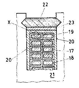
Figure 2 shows a cross section through a stator slot
with inserted bar;
Figure 3 shows an enlarged representation of the
detail X from Figure 2; and
Figure 4 shows an enlarged representation of the
detail Y from Figure 3.
DESCRIPTION OF THE PREFERRED EMBODINENTS
Referring now to the drawings, wherein like
reference numerals designate identical or corresponding
parts throughout the several views, a stator bar of an
electric machine in accordance with Figure 1 has a
straight coil section 11 in the slot region and bent
sections 12 and 13 in the winding overhang region. The
bar is provided with an insulation which is designated
::
' ' ~ ' ~ ,

2~94~2
in general by the reference numeral 14 and is thesub~ect matter of the present invention.
As emerges from the cross section in accordance
with Figure 2, the bar is constructed from a
multiplicity of mutually insulated component conductors
17 which are twisted in accordance with the Roebel
principle. Each component conductor has a component
conductor insulation 18 of known design. The component
conductors are combined to form a conductor bundle and
surrounded by a common insulating sleeve, the major
insulation l9, and are situated in a stator slot 20 in
the laminate stack 21 of the machine. The rods are
fixed by means of slot wedges 22 and wedge supports 23.
The structure of the ma~or insulation 19
follows from Figure 3, which shows an enlargement (not
to scale) of the detail X from Figure 2. The major
insulation 19 consists of a multiplicity of mutually
overlapping layers Ll, L2, L3, L4 ... of mica strips.
The innermost layer Ll comprises in this case a mica
layer 26 which is covered on both sides by textile
carriers 24, 25, preferably glass fiber fabric. In this
ca~e, a "textile carrier" is understood to be a strip
consisting of fibers or threads which by contrast with
a foil is tran~parent to impregnating resin in, across
and perpendicular to the strip direction. By contrast,
the layers L2, L3, L4 ... ad~oining it consist in each
case of one mica layer 27 which has only a single
textile carrier 28. The mica strip forming the layers
L2, L3, L4 ... is applied in this case in such a way
that the mica layer 27 points in each case to the
copper conductor 17.
It can easily be seen in Figure 4, which
represents an enlargement of the detail Y from Figure
3, that channels 31 which extend between the warp
thread~ 29 and weft threads 30 of the textile carrier
24 in the bar longitudinal direction are produced
between the mica layer 26 and the component conductor
surface 18. It is possible during the later
.
,
.
. . -

2~9~2
-- 5 --
impregnation of the major insulation for the
impregnating resin to pass through these channels to
virtually all points of the conductor surface, to wet
the latter reliably and in a short time, and to ensure
optimum bonding of the ma~or insulation to the
conductor.
Obviously, numerous modifications and varia-
tions of the present invention are possible in light of
the above teachings. It is therefore to be understood
that within the scope of the appended claims, the
invention may be practiced otherwise than as speci-
fically described herein.
-. - ~.
- ..
:
:

Representative Drawing
A single figure which represents the drawing illustrating the invention.
Administrative Status

2024-08-01:As part of the Next Generation Patents (NGP) transition, the Canadian Patents Database (CPD) now contains a more detailed Event History, which replicates the Event Log of our new back-office solution.

Please note that "Inactive:" events refers to events no longer in use in our new back-office solution.

For a clearer understanding of the status of the application/patent presented on this page, the site Disclaimer , as well as the definitions for Patent , Event History , Maintenance Fee  and Payment History  should be consulted.

Event History

Description Date
Inactive: IPC from MCD 2006-03-11
Application Not Reinstated by Deadline 2003-04-22
Time Limit for Reversal Expired 2003-04-22
Deemed Abandoned - Conditions for Grant Determined Not Compliant 2002-07-24
Deemed Abandoned - Failure to Respond to Maintenance Fee Notice 2002-04-22
Notice of Allowance is Issued 2002-01-24
4 2002-01-24
Letter Sent 2002-01-24
Inactive: Approved for allowance (AFA) 2002-01-09
Letter Sent 2000-04-27
Inactive: Status info is complete as of Log entry date 2000-04-27
Inactive: Application prosecuted on TS as of Log entry date 2000-04-27
All Requirements for Examination Determined Compliant 2000-04-06
Request for Examination Requirements Determined Compliant 2000-04-06
Application Published (Open to Public Inspection) 1993-12-11

Abandonment History

Abandonment Date Reason Reinstatement Date
2002-07-24
2002-04-22

Maintenance Fee

The last payment was received on 2001-03-27

Note : If the full payment has not been received on or before the date indicated, a further fee may be required which may be one of the following

  • the reinstatement fee;
  • the late payment fee; or
  • additional fee to reverse deemed expiry.

Patent fees are adjusted on the 1st of January every year. The amounts above are the current amounts if received by December 31 of the current year.
Please refer to the CIPO Patent Fees web page to see all current fee amounts.

Fee History

Fee Type Anniversary Year Due Date Paid Date
MF (application, 5th anniv.) - standard 05 1998-04-20 1998-03-23
MF (application, 6th anniv.) - standard 06 1999-04-20 1999-03-22
MF (application, 7th anniv.) - standard 07 2000-04-20 2000-03-17
Request for examination - standard 2000-04-06
MF (application, 8th anniv.) - standard 08 2001-04-20 2001-03-27
Owners on Record

Note: Records showing the ownership history in alphabetical order.

Current Owners on Record
ASEA BROWN BOVERI LTD.
Past Owners on Record
ROLAND SCHULER
Past Owners that do not appear in the "Owners on Record" listing will appear in other documentation within the application.
Documents

To view selected files, please enter reCAPTCHA code :


To view images, click a link in the Document Description column (Temporarily unavailable). To download the documents, select one or more checkboxes in the first column and then click the "Download Selected in PDF format (Zip Archive)" or the "Download Selected as Single PDF" button.

List of published and non-published patent-specific documents on the CPD .

If you have any difficulty accessing content, you can call the Client Service Centre at 1-866-997-1936 or send them an e-mail at CIPO Client Service Centre.

({010=All Documents, 020=As Filed, 030=As Open to Public Inspection, 040=At Issuance, 050=Examination, 060=Incoming Correspondence, 070=Miscellaneous, 080=Outgoing Correspondence, 090=Payment})


Document
Description 
Date
(yyyy-mm-dd) 
Number of pages   Size of Image (KB) 
Representative drawing 1998-11-03 1 9
Representative drawing 2002-01-09 1 13
Description 1994-03-26 5 171
Drawings 1994-03-26 1 26
Claims 1994-03-26 1 21
Abstract 1994-03-26 1 17
Reminder - Request for Examination 1999-12-20 1 119
Acknowledgement of Request for Examination 2000-04-26 1 178
Commissioner's Notice - Application Found Allowable 2002-01-23 1 164
Courtesy - Abandonment Letter (Maintenance Fee) 2002-05-20 1 183
Courtesy - Abandonment Letter (NOA) 2002-10-01 1 170
Fees 1997-03-23 1 56
Fees 1996-03-18 1 59
Fees 1995-03-28 1 59