Note: Descriptions are shown in the official language in which they were submitted.
20945~3
Title TWO-PIECE WEDGE-CLAMP SYSTEM FOR
INTERCHANGEABLE BUCKET TEETH
Field of the Invention
This invention is related generally to digging,
excavating and dragline mining equipment and, more
particularly, to tooth assemblies used on the digging
buckets of such equipment.
Background of the Invention
Certain types of earth-moving and excavating
machinery are equipped with digging buckets capable of
holding anywhere from a fraction of a cubic yard to
several cubic yards of material. One type of machine
using a large digging bucket is called a walking
dragline. Such draglines are often used in strip mining
to remove "overburden~ material covering, e.g., coal or
ore, and to remove the product being mined. A large
.~r r
~.~,
-2- 2094553
dragline may represent an investment of well over a
million dollars; downtime is expensive, adds to the
consumer cost of the product being mined and must be
minimized.
Draglines are very large and include an enclosed
machinery deck mounted on movable "legs" for machine
transportability over a limited area. The machinery deck
includes drive motors, cable reels, clutches and the like
for manipulating a boom and boom-suspended bucket. The
boom extends outward from the machinery deck by a
distance of, for example, 300 feet or so. The digger
bucket is attached to cables, one of which extends
downward from the end of the boom to support the bucket
weight and the other of which extends between the bucket
and the machinery deck.
Digging is by lowering the bucket onto the material
to be removed and dragging the bucket toward the
machinery deck. As the bucket is drawn toward the
machine, its digging teeth bite into the material as the
bucket fills. After the bucket is filled, the boom is
swung laterally and the bucket tipped for dumping the
load. For a large dragline, the bucket capacity may be
80-90 cubic yards or even larger. And there are other
types of machines, e.g., excavators, backhoes and the
like, which use digger buckets mounted on articulated
arms.
A large bucket may have several tooth assemblies,
the individual components of which are typically quite
large. For example, the tip of a digging tooth for a
large bucket may have a length of 13 inches or so (as
measured in the direction of digging), a width of about
12 inches and weigh about 160 pounds. And a large bucket
itself may weigh several thousand pounds.
More specifically, each hollow, sheath-like tip is
fitted over and supported by a tooth "nose" or base. The
tip (which is generally hollow to receive the base) has a
pair of apertures, one each in the top and bottom tip
B
3 2091~53
plate. The base has a single vertical aperture. When
the tip is fully seated on the base, the apertures are
aligned and form a single vertical "top-to-bottom"
aperture.
In conventional digging tooth assemblies, the tip is
retained on the base by a wedge-shaped member sized 50
that when in place, a smaller aperture still remains. A
wedge-shaped pin is driven (often with a sledge hammer)
into this smaller aperture and retains the tip in place
solely by friction. Because such digger buckets are
subjected to severe use, often in hard mineral such as
limestone, coal or rock, the bucket digging teeth wear
and the above-described base/tip arrangement is
configured in anticipation of periodic tip and/or wedge
pin replacement.
The conventional wedge pin arrangement is attended
by a number of disadvantages. One is that, over time,
the wedge pins are knocked out or they can simply become
loose and fall out. The tip then slips off of anA falls
from the base which may soon be broken off by continued
digging. And repairing a broken base is a much more
substantial task than replacing a worn tooth tip.
Another disadvantage is that the wedge pin is usually
hardened and repetitive hammering may cause the pin to
splinter, sending shards of metal flying like shrapnel.
Yet another disadvantage is that the hardened wedge
pin lacks significant resilience or ductility and this
fact promotes pin loosening with slight wear. In other
words, the parts are not self-adjusting to any
significant degree.
Even if the wedge pin remains secure over the life
of the tip, pin removal preparatory to tip replacement is
a substantial task. Because such pins are driven from
the top of the tooth downward, they must be removed by
driving them upward using a hammer and drift pin. Access
to the underside of the bucket is required to do this--
and a bucket weighing several thousand pounds presents an
_4_ ~09 ~553
imposing "positioning task." If the bucket teeth are
merely lifted away from the ground (rather than totally
inverting the bucket), an individual is required to work
beneath the lifted bucket and this presents unnecessary
risks.
Some wedge pin arrangements involve an aperture
extending horizontally across the width of the tooth tip
and tooth base. In theory, wedge pins should then be
removable without gaining access to the bottom of the
bucket. However, there is often too little space between
tooth assemblies to permit either satisfactory wedge pin
driving or later pin removal.
An improved apparatus and method for tooth tip
retention which avoids drive pins, which eliminates a
need for clear access to the bottom of the bucket and
which retains the tooth tip by means other than merely
friction would be an important advance in the art.
Obiects of the Invention
It is an object of this invention to provide an
improved apparatus and method for tooth tip retention
which overcomes some of the problems and shortcomings of
the prior art.
Another object of this invention is to provide an
improved apparatus and method for tooth tip retention
which avoids driving wedge pins.
Another object of this invention is to provide an
improved assembly and method for tooth tip retention
which eliminates a need for clear access to the bottom of
the bucket.
Yet another object of this invention is to provide
an improved assembly and method for tooth tip retention
which retains the tooth tip by means other than merely
friction.
Another object of this invention is to provide an
improved assembly and method for tooth tip retention
~5~ 209~55~
which permits tooth tip removal from the top of the
bucket.
Another object of this invention is to provide an
improved assembly and method for tooth tip retention
which utilizes readily-available tools.
Still another object of this invention is to provide
an improved assembly which provides a degree of "self-
adjustment." How these and other objects are
accomplished will become apparent from the following
descriptions and the drawing.
Summary of the Invention
An aspect of the invention is an improvement in a
digging tooth assembly having first and second wedged
members retaining a digging tooth tip on a tooth base.
The improvement comprises a tension member which is
coupled to the first member and engages the second
member. The tension member has an adjustable effective
length whereby the first member is drawn into wedged
engagement with the second member as the effective length
of the tension member is changed.
In a highly preferred arrangement, the tension
member includes a bolt coupled to the first member and
extending through a plate in overlapping engagement with
the second member. This effectively "links" the two
members by the bolt so that when the bolt is tightened,
the members are firmly wedged.
The improved assembly is arranged to be accessed
solely through the open spatial region above the
assembly. That is, the tension member includes an
adjustment device (a bolt head, nut or the like) which is
accessible through the region. The adjustment device is
rotatable for changing the effective length of the
tension member, i.e., tightening or loosening such
tension member, thereby wedging and de-wedging the
members.
-6- 209~53
The tooth base includes an aperture having a forward
face, i.e., a face toward the tip end. The second wedge-
like member includes an angled face having an upper
portion and a lower portion and the upper portion is
closer to the forward face than the lower portion. Such
configuration permits drawing the first wedge-like member
upward (as opposed to driving a pin downward) to wedge
the members together.
In one highly preferred embodiment, the tension
member includes a bolt and the bolt and the first member
are in threaded engagement one to the other. The first
member has an angled face in sliding engagement with the
angled face of the second member as the members are drawn
together. The angled faces are conformable grooved or
serrated, thereby increasing the frictional surface areas
of the faces. Even though friction comprises only one
force component retaining the tip on the base, such
serrated configuration maximizes such friction.
In another highly preferred embodiment, the bolt and
the first member are coupled to one another by a pivot
joint rather than being threaded together. The angled
face of the second wedge-like member has a notch and the
bolt is mounted for pivoting movement into and out of the
notch for, respectively, installing and removing the
tooth tip.
That plate through which the bolt extends and which
is in overlapping engagement with the second member
comprises a self-aligning washer having mating concave
and convex surfaces. During installation and tightening,
such washer compensates for changes in angularity between
the bolt long axis and the angled face. Such
compensation also occurs as the parts wear.
Another aspect of the invention involves a method
for assembling a digging tooth assembly having (a) an
open spatial region above the assembly and (b) a tooth
base supporting a tooth tip. Such assembly is of the
type wherein the tip and the base define an aperture.
2û94553
The method improvement comprises the steps of inserting a
first wedge-like member through the spatial region into
the aperture, inserting a second wedge-like member
through the spatial region into the aperture and drawing
the first member toward the spatial region to wedged
engagement with the second member.
In one highly-preferred variant of the method, the
wedge-like members are inserted into the aperture
substantially simultaneously. The first wedge-like
member is threaded to a bolt extending through a plate in
overlapping engagement with the second me~ber and the
drawing step includes turning the bolt to decrease the
distance between the first member and the plate.
In another highly-preferred variant of the method,
the first wedge-like member and the second wedge-like
member are inserted into the aperture in sequence. The
first wedge-like member has a bolt coupled thereto by a
pivot joint, the second member has a notch and the
drawing step includes pivoting the bolt into the notch
and tensioning the bolt by tightening the bolt nut.
Further details of the inventive assembly and method
are set forth in the following detailed description and
the drawing.
Brief DescriPtion of the Drawing
FIGURE 1 is a side elevation view of a walking
dragline in operation.
FIGURE 2 is a side elevation view of a bucket used
on the dragline of FIGURE 1.
FIGURE 3 is a bottom plan view of the bucket of
FIGURE 2 taken in the viewing plane 3-3 thereof.
FIGURE 4 is an exploded isometric view of a first
embodiment of the invention. Hidden surfaces of parts
are shown in dashed outline.
FIGURE 5 is a side elevation view of the first
embodiment of the invention shown in an initial insertion
position in a tooth assembly. Parts are shown in cross-
209~5~3
section, other parts are broken away and hidden surfaces
of parts are shown in dashed outline.
FIGURE 6 is a side elevation view like FIGURE 5 and
showing the invention in an intermediate position in a
tooth assembly. Parts are shown in cross-section, other
parts are broken away and hidden surfaces of parts are
shown in dashed outline.
FIGURE 7 is a side elevation view like FIGURE 5 and
showing the invention in the final tip-retaining position
in a tooth assembly. Parts are shown in cross-section,
other parts are broken away and hidden surfaces of parts
are shown in dashed outline.
FIGURE 8 is an isometric view of a second embodiment
of the invention. Hidden surfaces of parts are shown in
dashed outline.
FIGURE 9 is a side elevation view of the first
wedging member of the second embodiment of the invention
in an initial insertion position in a tooth assembly and
shown in conjunction with an installation tool. Parts
are shown in cross-section and other parts are broken
away.
FIGURE 10 is a side elevation view of the second
embodiment of the invention with the second wedging
member installed and the first wedging member in an
intermediate position in a tooth assembly. The first
wedging member is shown in conjunction with an
installation tool. Parts are shown in cross-section and
other parts are broken away.
FIGURE 11 is a side elevation view of the second
embodiment of the invention in a final position in a
tooth assembly prior to tightening the adjustment device.
The invention is shown in conjunction with an
installation tool. Parts are shown in cross-section and
other parts are broken away.
FIGURE 12 is an isometric view of a tooth tip
retained on its base by a second embodiment of the
invention.
209 1553
g
FIGURE 13 is a side elevation view of a prior art
arrangement for retaining a tooth tip.
FIGURE 14 is a cross-section, side elevation view
like that of FIGURE 11 but with the adjustment device
5 tightened and the installation tool removed.
FIGURE 15A is a bottom plan view of a modification
of the first wedging member of the second embodiment of
the invention. Surfaces of portions are shown in dashed
outline.
FIGURE 15B is a side elevation view of the first
wedging member of FIGURE 15A taken along the viewing
plane 15B-15B thereof. Parts are broken away and
surfaces of portions are shown in dashed outline.
Detailed Description of Preferred Embodiments
Before describing the embodiments of the inventive
digger tooth tip retention assembly 10, it will be
helpful to appreciate how bucket digging teeth are used
and how a tooth tip is conventionally retained on the
tooth base. Following these descriptions, details of the
new tip retention assembly 10 are provided.
Referring to FIGURES 1, 2 and 3, the illustrated
walking dragline 11 includes a machinery deck 13, an
extended boom 15 and cables 17, 19 hooked to the digging
bucket 21. The cable 17 raises and lowers the bucket 21
and the cable 19 draws the bucket 21 toward the dragline
11 to load material into the bucket 21. The bucket teeth
23 bite into such material which fills the bucket 21 as
it moves. When used with the exemplary dragline 11, such
teeth 23 point toward the dragline 11 during digging. Of
course, it should be clearly understood that buckets with
replaceable tooth tips are used on a wide variety of
digging machines; the illustrated dragline 11 is but one
example of such a machine.
Referring to FIGURE 13, a prior art retaining
assembly 161 includes a wedge block 163 fitted into the
aligned apertures of the tooth base 165 and the tooth tip
209~53
10--
167. The block 163 is of substantially consistent
thickness from top to bottom and has upper and lower
protrusions 169 which overlap the base 165, help retain
the block 163 in vertical position and help urge the tip
167 tightly onto the base 165 as the wedge pin 171 is
driven home. The pin 171 is driven top-down into the
opening between the block 163 on one side and the base
165 on the other. Retained solely by friction, the pin
171 must be driven out from the bottom with a drift pin
(not shown).
In this specification, terms such as "forward,"
"rear" and the like are used. Such terms are used with
respect to the tip of a digging tooth in that "forward"
means toward such tip, "rear" means away from such tip
and so forth. Stated otherwise (and by way of example),
a "forward" surface is closer to such tip than is a
"rear" surface.
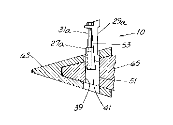
Referring now to FIGURES 4, 5, 6 and 7 a first
highly preferred embodiment of the inventive assembly 10
will now be described. The assembly 10 includes first
and second wedging members 27a and 29a, respectively. A
tension member 3la such as a bolt is coupled to the first
member 27a, engages the second member 29a and has an
adjustment device 33a, e.g., the bolt head, rotatable for
tensioning. The tension member 31a has an adjustable
effective length whereby the first member 27a is drawn
upward into wedge engagement with the second member 29a
as the effective length of the tension member 3la is
changed by rotating the adjustment device 33a.
More specifically, the first wedging member 27a has
generally parallel side surfaces 35, a forward surface 37
generally coplanar with the front face 39 of the base
aperture 41 and a rear surface 43 angled upward and
toward the forward surface 37. The member 27a has a
generally vertical hole 45 threaded to receive the bolt
or similar tension member 31a. It is to be appreciated
that depending upon the shape of the front face 39 of the
209~5~3
--11--
aperture 41, surface 37 may be curved as shown in dashed
outline in FIGURE 4 or may be of some other shape.
The second wedging member 29a has generally parallel
side surfaces 47, a rear surface 49 generally parallel to
the rear face 51 of the base aperture 41 and a forward
surface 53 angled upward and away from the rear surface
49. The forward surface 53 has an upper portion 55 which
is closer to the forward surface 39 than is the lower
portion 57 of such surface 53.
The second wedging member 29a also has upper and
lower protrusions 59a and 61a, respectively, which serve
much the same function as the protrusions 169 described
above with respect to FIGURE 13. As will become
apparent, the rear surface 43 of the first member 27a
bears against and slides along the forward surface 53 of
the second member 29a as the tension member 31a is
tightened to retain the tooth tip 63 on the base 65 or is
loosened to "de-wedge" the members 27a, 29a and replace
- the tip 63.
"Linking" of the members 27a, 29a can be in any way
that permits drawing the members 27a, 29a toward one
another (or permits drawing one member toward the other)
when the adjustment device 33a (e.g., the head of a bolt)
is rotated to tension the member 3la. In one preferred
arrangement, the second wedging member 29a has a forward
protruding plate 67 with a slotted hole 69 through it for
receiving the tension member 31a. Such slotted hole 69
extends in a forward/rear direction to permit slight
movement of the tension member 3la along the hole 69 and
with respect to the second wedging member 29a as the
adjustment device 33a is tightened or loosened.
Since friction (in addition to bolt tension) helps
prevent the members 27a, 29a from sliding apart, the
members 27a, 29a shown in FIGURES 4-7 each include
conformably-shaped serrations 71 on the rear surface 43
and forward surface 53, respectively. Such serrations
increase the frictional surface area.
209~5~3
-12-
Referring next to FIGURES 8 through 12, a second
highly preferred embodiment of the inventive assembly 10
will now be described. As with the first embodiment, the
second embodiment has first and second wedging members
27b and 29b, respectively. A tension member 31b such as
a bolt is coupled to the first member 27b, engages the
second member 29b and has an adjustment device 33b, e.g.,
a nut threaded to the bolt, rotatable for tensioning.
The tension member 3lb has an adjustable effective length
whereby the first member 27b is drawn upward into wedge
engagement with the second member 29b (or is de-wedged
from the second member 29b) as the effective length of
the tension member 3lb is changed by rotating the
adjustment device 33b.
The first wedging member 27b has a curved forward
surface 73 which bears against the forward face 39 of the
base aperture 41. The surface 75 of the first wedging
member 27b and the mating surface 85 of the second
wedging member 29b are angled slightly upward and
forward. Therefore, member 27b is urged against the
forward face 39 and rear protrusions 59b, 61b of second
member 29b are urged against the rear edges of the upper
and lower openings in the tooth tip 63. The first member
27b also has an interior, generally U-shaped cavity 77
which opens via hole 79 into pivot pocket 81 having a
curved top surface shaped somewhat like a longitudinally-
cut half cylinder. As will become apparent from further
explanation below, the pocket 81 receives the special
pivot head 83 of a bolt-like tension member 31b.
The second member 29b has rear protrusions 59b, 61b
which function much like the protrusions 169 described
above. Of course, such protrusions 59b, 61b may also be
curved or otherwise to match the shape of upper and lower
openings of the tooth tip 63. The member 29b has a
generally planar, angled forward surface 85, the upper
portion 87 of which is closer to the forward face 39 of
the aperture 41 than is the lower portion 89. A
-13- 209~5~
receiving notch 91 is formed in the surface 85 and
terminates in a U-shaped pocket 93. As shown in FIGURES
8 and 11, the notch 91 is progressively deeper as viewed
from the notch bottom upward toward the pocket 93 and has
an angle and depth selected to receive the tension member
3lb which can be pivoted into or out of the notch 91 as
described below.
Referring to FIGURES 11 and 14, the tension member
31b comprises a special bolt having a pivot head 83 which
is half-cylindrical and generally conformably shaped to
fit into and pivot within the pivot pocket 81 to form a
pivot joint. As seen in FIGURES 9-11, the long axis 95
of the half cylinder pivot head 83 extends into and out
of the drawing so that the tension member 3lb readily
tips forward or rearward (as referred to the tip 63; left
or right in the plane of the drawing) but is
substantially restrained from lateral tipping (as
referred to the tip 63; into or out of the plane of the
drawing).
The bolt extends upward first through a plate-like,
two-piece spherical self-aligning washer 97 and then
through a disc spring 99. A prevailing-torque nut device
33b is threaded onto the upper end of the bolt and the
washer 97, the spring 99 and the device 33b are commonly
available hardware. A prevailing torque nut device is a
nut with, for example, deformed threads or a nylon insert
that prevents the device from being loose on a bolt even
though the nut and bolt are not tightened to tension.
The spring 99 helps retain tension and the washer 97
maintains effective force transfer between the tension
member 31b and the floor 101 of the pocket 93 as the
angle of the bolt long axis changes slightly with respect
to the angled surface 85 and the pocket 93 as the device
33b is tightened or loosened.
Referring again to FIGURES 3-7 and 8-12, a method
for assembling a digging tooth assembly will now be set
forth. One of the significant advantages of the new
-14-
20945~3
retention assembly 10 is that, in either embodiment, such
assembly 10 can be inserted through the open spatial
region 103 above the assembly lo. The improved method
comprises the steps of inserting the first wedge-like
member 27a or 27b through the spatial region 103 into the
aperture 41, inserting the second wedge-like member 29a
or 29b through the spatial region 103 into the aperture
41 and drawing the first member 27a, 27b toward the
spatial region 103 and into wedged engagement with the
second member 29a, 29b.
In one highly-preferred variant of the method
involving the first embodiment of FIGURES 5-6 (which
generally show an assembly sequence), the wedge-like
members 27a, 29a are inserted into the aperture 41
substantially simultaneously. The first wedge-like
member 27a is threaded to a tension member 31a extending
through the plate 67 and the drawing step includes
turning the adjustment device 33a to decrease the
distance between the first member 27a and the plate 67.
In another highly-preferred variant of the method
involving the second embodiment of FIGURES 9-10 (which
also generally shown an assembly sequence), the first
wedge-like member 27b and the second wedge-like member
29b are inserted into the aperture 41 in sequence. The
first wedge-like member 27b has a tension member 31b
coupled thereto by a pivot joint, the second member 29b
has a notch 91 and the drawing step includes pivoting the
member 31b into the notch 91 and tensioning the member
31b by tightening the device 33b.
In the instance of the second embodiment of the
assembly lo (shown in FIGURES 8-11), insertion of the
first wedge-like member 27b is by threading an
installation tool 105 onto the upper exposed end of the
member 31b and lowering the tool 105 and the member 27b
down through the aperture 41 to extend somewhat below the
aperture 41 as shown in FIGURES 9 and 10. After so
doing, there is ample clearance to lower the second
-15- 209~5~3
wedging member 29b into the aperture 41 and position it
as shown in FIGURE 10.
The tension member 3lb is then pivotably tipped into
the receiving notch 91 and the installation tool 105 is
removed. A conventional tool, e.g., a socket wrench, is
then used to tighten the adjustment device 33b while
retaining the washer 97 in contact with the floor 101 of
the pocket 93. As the device 33b is tightened, the first
wedging member 27b is drawn into wedged relationship with
the second wedging member 29b and the tooth tip 63 is
firmly retained on the base 65.
Several highly desirable advantages are apparent
from the foregoing. One is that the retention assembly
10 can be installed and removed through the open spatial
region 103 above the tooth assembly 23. There is no need
to overturn the bucket 21 or to work under a propped-up
bucket 21. And such installation and removal is without
resorting to drive pins 171, removing such pins 171 with
drift pins and the like. Another advantage is that the
tooth tip 63 is retained on the base 65 by means other
than friction alone. While friction is helpful in
retention, there is also a bolt-like tension member 31
retaining the wedging members 27, 29 in a tightly-fitted
position. That is, some wear can (and will) occur but
because member 31 is in tension and therefore stretched
slightly, such wear will not cause the assembly 10 to
immediately become loose.
And that is not all. In the first embodiment of the
assembly 10 shown in FIGURES 4-7, the tension member 3la
can be loosened and then struck from the top to "de-
wedge" the first member 27a from the second member 29a.
In the second embodiment of the assembly 10 shown in
FIGURES 8-12, 14, the tension member 31b can be loosened
and the upper end of member 27b then struck to accomplish
the same purpose. However, there is yet another way to
configure the first member 27b so that the second
embodiment of the assembly 10 can be easily de-wedged.
2094553
-16-
Referring to FIGURES 15A and 15B, the member 27b
includes a pivot pocket 107 and a hollow "arm" 109
vertically adjacent to and at 90 to the pocket 107. The
pocket 107 is similar in function to pocket 81 shown in
FIGURE 8 in that the T-shaped pivot head 83 is positioned
in pocket 107 when the assembly 10 is installed.
However, pocket 107 is unlike pocket 81 in that
pocket 107 is not directly open to the bottom of the
member 27b. Rather, pocket 107 has a "floor" 113 and
when the adjustment device 33b is loosened and pivot head
83 lowered to contact the floor 113, the user can then
tap the upper end of the tension member 3lb to drive the
member 27b downward and de-wedge the assembly 10.
However, arm 109 (which is at 90 to pocket 107) is
open to the bottom of the member 27b so that the member
31b can be installed and removed. More particularly,
member 3lb is installed by inserting it upward through
arm 109 (with the pivot head 83 in registry with arm 109)
until the pivot head 83 is above the floor 113. The
member 31b is then rotated 90 until the pivot head 83 is
in registry with pocket 107 (and therefore at a 90 angle
to the arm 109) and the head 83 is thereupon seated in
the pocket 107.
While the invention has been described in connection
with a few embodiments, it is to be clearly appreciated
that such embodiments are by way of example and not by
way of limitation.