Language selection

Search

Patent 2094655 Summary

Third-party information liability

Some of the information on this Web page has been provided by external sources. The Government of Canada is not responsible for the accuracy, reliability or currency of the information supplied by external sources. Users wishing to rely upon this information should consult directly with the source of the information. Content provided by external sources is not subject to official languages, privacy and accessibility requirements.

Claims and Abstract availability

Any discrepancies in the text and image of the Claims and Abstract are due to differing posting times. Text of the Claims and Abstract are posted:

  • At the time the application is open to public inspection;
  • At the time of issue of the patent (grant).
(12) Patent: (11) CA 2094655
(54) English Title: AUTOMOTIVE ACCESSORY DRIVE BELT TENSIONER
(54) French Title: TENDEUR AUXILIAIRE DE COURROIE D'ENTRAINEMENT D'UN MOTEUR D'AUTOMOBILE
Status: Expired and beyond the Period of Reversal
Bibliographic Data
(51) International Patent Classification (IPC):
  • F16H 7/12 (2006.01)
  • F02B 67/06 (2006.01)
  • F16H 7/08 (2006.01)
(72) Inventors :
  • BUSHMAN, THOMAS S. (United States of America)
  • LAHVIC, THOMAS R. (United States of America)
  • MECKSTROTH, RICHARD J. (United States of America)
  • REBANDT, ROBERT, II (United States of America)
  • VAUGHN, TIMOTHY T. (United States of America)
(73) Owners :
  • FORD MOTOR COMPANY OF CANADA, LIMITED
(71) Applicants :
  • FORD MOTOR COMPANY OF CANADA, LIMITED (Canada)
(74) Agent: MARKS & CLERK
(74) Associate agent:
(45) Issued: 2000-05-23
(22) Filed Date: 1993-04-22
(41) Open to Public Inspection: 1993-10-30
Examination requested: 1997-02-12
Availability of licence: N/A
Dedicated to the Public: N/A
(25) Language of filing: English

Patent Cooperation Treaty (PCT): No

(30) Application Priority Data:
Application No. Country/Territory Date
07/874,883 (United States of America) 1992-04-29

Abstracts

English Abstract


An arm assembly for an automotive engine accessory
drive belt tensioner has a wound spring which is
permanently captured upon the arm by a retainer which is
effective not only prior to installation of the arm upon
an engine, but also after the installation and removal of
the arm from an engine.


Claims

Note: Claims are shown in the official language in which they were submitted.

- 6 -
The embodiments of the invention in which an exclusive
property or privilege is claimed are defined as follows:
1. An arm assembly for an automotive engine
accessory drive belt tensioner, comprising:
an arm having first and second ends;
a tensioner pulley mounted on said first end;
a movable bearing section integral with said
second end, with said bearing section being adapted for
engagement with a fixed bearing section carried upon an
engine;
a wound spring mounted at said second end, with
said spring having inner and outer ends, with the inner
end being operatively connected with said movable bearing
section; and
retainer means at said second end for securing the
outer end of said spring such that the outer end is
permanently captured within a space defined by said
retainer means and said second end such that the outer
end of the spring has limited freedom to move
rotationally with respect to said arm, while being
restrained against axial movement with respect to the
second end of the arm, with the result that the arm may
be disengaged from said fixed bearing section without the
outer end of the spring becoming disengaged from the
second end of the arm.
2. An arm according to Claim 1, further
comprising a rotational stop boss carried on said second
end and adapted to engage a stationary abutment structure
carried upon said engine such that the rotation allowed
by said boss and said abutment structure is less than the
rotation allowed the second end of the spring by said
retainer means.

- 7 -
3. An arm according to Claim 1, wherein said
retainer means comprises a generally L-shaped structure
having a first leg in contact with the second end of the
arm and extending axially along an arc defined by the
rotational movement of the outer end of the spring and a
second leg extending radially inwardly from said first
leg in a direction parallel to, but separated from, the
second end of the arm, with said L-shaped structure
further comprising an abutment for preventing the spring
from unwinding when said arm is not installed on an
engine.
4. An arm according to Claim 1, wherein said
pulley comprises a unitary cup-shaped member with a base
having a rim depending therefrom for contacting a drive
belt, with a plurality of acoustical apertures formed in
the rim.
5. An arm assembly for an automotive accessory
drive belt tensioner, comprising:
an arm having first and second ends;
a tensioner pulley mounted on said first end;
a movable bearing section integral with said
second end, with said bearing section being adapted for
engagement with a fixed bearing section carried upon an
engine;
a wound spring mounted at the second end of the
arm, with said spring having inner and outer ends, with
the inner end being operatively connected with said
movable bearing section; and
retainer means integral with said arm for securing
the outer end of said spring, with said retainer means
preventing said outer end from unwinding and moving
axially with respect to the second end of the arm prior
to attachment of the arm to an engine.

- 8 -
6. A tensioner assembly for an automotive engine
accessory drive belt, comprising:
a tensioner arm having first and second ends;
a pulley mounted on said first end;
a movable bearing section integral with said
second end, with said bearing section being adapted for
engagement with a fixed bearing section carried upon an
engine;
a fixed bearing section which is integral with a
cover adapted to enclose part of an engine;
a wound spring mounted at said second end, with
said spring having inner and outer ends, with the inner
end being operatively connected with said movable bearing
section; and
retainer means, including abutment means, at said
second end for securing the outer end of said spring such
that the outer end is permanently captured within a space
defined by said retainer means and said second end such
that the outer end has limited freedom to move
rotationally with respect to said arm, while being
restrained against axial movement with respect to the
second end of the arm, with the result that the arm may
be disengaged from said fixed bearing section without the
outer end of the spring becoming disengaged from the
second end of the arm.
7. A tensioner according to Claim 6, further
comprising a spring anchor carried upon said cover such
that the anchor engages the outer end of the spring and
reacts with the spring so as to urge the outer end of the
spring away from the abutment means of said retainer.

- 9 -
8. A tensioner according to Claim 6, wherein said
pulley comprises a cup-shaped member with a base and a
rim for contacting a drive belt and having a plurality of
acoustical apertures formed in the rim.
9. A tensioner assembly for an automotive engine
accessory drive belt, comprising:
a tensioner arm adapted for pivotable mounting to
an engine; and
a drive belt contact pulley mounted on said arm,
with said pulley comprising a cup-shaped member with a
base and a rim for contacting a drive belt and having a
plurality of acoustical apertures formed in the rim.

Description

Note: Descriptions are shown in the official language in which they were submitted.


2 ~ 5 ~
AUTOMOTIVE ACCESSORY DRI~E BELT TENSIONER
Backqround of the Invention
Automotive accessory drive belt tensioners are
commonly used for maintaining proper tightness o
flexible members which power such accessories as a water
pump, air conditioning compressor, alternator, and power
steering pump. Although many types of tensioners are
used, the spring loaded variety is most common.
U.S. 4,832,665 to Kadota et al. discloses a spring
type tensioner in which the power spring is immobilized
prior to engagement of the tensioner with an engine by
means of a pin, 27, which ma~ be extracted after the
tensioner is bolted to the engine. A possible problem
could occur with the device shown in the '665 patent
after pin 27 is e~tracted. If the tensioner is removed
from the engine without reinsertion of pin 27, such as
would likely he the case after an engine equipped with
the tensioner has been in use for some time, the spring
could be allowed to unwind violently. A tensioner arm
assembly according to the present invention obviates this
prohlem by controlling the location of the outer and
inner ends of the spring not only before the tensioner
arm assembly is installed in the engine, but also during
and after removal of the arm assembly from an engine.
SummarY of the Invention
A tensioner assembly for an automotive engine
accessory drive belt includes a tensioner arm having
first and second ends, with a pulley mounted on the first
end and a movable bearing section integral with the
second end, with the movable bearing section being
adapted for engagement with a fi~ed bearing section

- 2 - 2~6~
carried upon an engine. Such a fixed bearing section may
be integral with a cover adapted to enclose part of an
engine. The tensioner further includes a wound spring
mounted at the second end of the tensioner arm, with the
spring havin~ inner and outer ~nds, and wi.th the inner
end being operatively connect~d with the movable bearing
section of the arm. Finally, retainer means at the
second end of the arm secures the outer end of the spring
such that the outer end is permanently captured within a
space defined by the retainer means and the second end of
the arm such that the outer end of the spring has limited
freedom to move rotationally with respect to the arm,
while being restrained against axial movement with
respect to the remainder of the arm. The result o~ the
restraint imposed by the retainer means is that the arm
may be disengaged from the fixed bearing section without
the outer end of the spring becoming disen~aged from the
second end of the arm.
20Brief Description of the Drawinqs
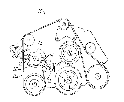
Figure 1 illustrates an engine having a tensioner
assembly according to one aspect of the present invention.
Figure ~ illustrates a sectional view of a
tensioner according to the present invention taken along
line 2-2 of Figure 1.
Figures 3 and 4 are plan views of a tensioner
assembly according to the present invention, shown in two
different rotational orientations.
30Figure 5 illustrates a rotational stop boss
incorporated into the present tensioner.
Figures 6 and 7 illustrate details of a spring
retainer according to an aspect of the present invention.
Figure 8 illustrates a second and third embodiment
according to the present invention.

2 ~
-- 3 --
Detailed Description of the Invention
As shown in Figure l, an engine, lO, having an
accessory drive belt, 26, is equipped with a belt
tensioner, 12, which is applied to a front cover, 14.
Continuing with Figure 2, tensioner arm 16 has first end,
18, to which a belt contacting pulley, 22, is journaled.
The second end, 20, of arm 16 includes a movable bearing
section, 28, which is supported upon a fi~ed bearing
section, 30, carried upon cover 14. Those skilled in the
art will appreciate in view of this disclosure that fi~ed
bearing section 30 need not be integral with the cover of
an engine, but could also be a part of a bracket which is
bolted to the cover or other part of an engine.
As shown in Figures 3 and 4, a tensioner according
to the present invention has a wound spring, 32, mounted
at second end 20 of arm 16. Spring 32 has an inner end,
34, which is operatively connected with movable bearing
section 28. Outer end 36 of spring 32 must of course
react with a fi~ed anchor so as to allow the force of the
spring to bias pulley 22 in the direction required to
tension belt 26. Accordingly, spring anchor 38 is
provided upon cover 14 such that anchor 38 engages outer
end 36 of spring 32 and reacts with spring 3~ so as to
urge end 36 away from abutment 42 of retainer 40.
Prior to installation of the tensioner upon the
engine and prior to tensioning oE the drive belt, outer
end 36 oE spring 32 contacts abutment 42, as illustrated
in Figure 3. Unlike prior art spring retainers, retainer
40 is never removed from arm 16, even when the arm has
been installed upon an engine. Thus, spring 32 can
impose a load upon pulley 22, tending to rotate the
tensioner in the counterclockwise direction, as viewed in
Figures l, 3 and 4, only after outer end 36 contacts

~ 4 ~
spriny anchor 38. Such a position is shown in Figure 4.
It may be seen from Figure 4 that retainer 40 does not
inhibit the operation of spring 32.
Figures 3, 4 and 5 illustrate the rotational
limitation function of the pre5ent tensioner.
Accordingly, stop 46 which is part of second end 20 of
arm 16 engages stationary stcp bosses 48, which ar~
carried upon cover 19. Stop 46 and bosses 48 are
arranged such that the rotation allowed by the
interaction of the bosses and stop will be less than the
rotation allowed spring end 36 by the dimensions of
reta;ner 40. As a result, the spring end 36 will not
bottom out on retainer 40 as the tensioner assembly is
moved through the rotation allowed by stop 46 and
bosses 48.
Figures 6 and 7 further illustrate the
cons-truction of retainer 40. Beginniny with Figure 6, it
may be seen that spring end 36 is maintained in axial
reg;stry with arm 16 by leg 40b o~ an L~shaped structure
- 20 comprising legs 40a and 40b. Leg 40a e~tends a~ially
along an arc defined by rotational movement of end 36.
This is shown in Figure 7. Leg 40a provides an
attachment means for leg 40b. As a ~hole, retainer 40
prevents spring end 36 from becoming disengaged from arm
16 at any tirnel either before, or during, or after
installation of the arm upon an engine. Retainer 40 also
includes abutment 42 which allows spring 32 to be
pretensioned before installation upon an engine. As
shown in Fisures ~ and 4, abutment 42 extends a
sufficient radius rom spring anchor 38 so that spring
anchor 38 is able to bear upon end 36. Although a
tensioner according to the present invention has been
constructed with retainer 40 rivetea in place, those
skilled in the a~t will appreciate in view of this
disclosure that r~tainer 40 ma~r be either cast or

_ 5 _ ~og ~6~ 5
otherwise formed as one piece with arm 16, or,
alternatively, the retainer may be attached by weld;ng or
by other means known in the art and suggested by this
disclosure.
F.igure 8 illustrates another embodiment according
to the present.invention in which arm 16 has an integral
retainer means, 50, which prevents outer end 36 from
unwinding and moving axially with respect to arm 16 prior
to attachment of the arm to an engine~
It has been determined that the noise
characteristics of an engine equipped with a tensioner of
the type illustrated ma~ be enhanced by providing a
plurality of acousti.cal apertures, 24, (see Figure 8~,
which are equally spaced about rim 22b. The character
and level of the sound produced by drive belt 26 as it
rnoves over rim 22b is a function of the diameter of
apertures 24. In general, the larger diameter of the
apertures, the greater the sound power produced. As belt
~6 contacts the surface of rim 22b, the belt deforms ~:~
slightly over the apertures creating sound. The
synchronous sound generated modifies the engine sound
perceived by the listener.
Those skilled.in the art will appreciate in view
of this disclosure that a tensioner according to the
presént invention could be emp.loye~ not only with
accessory drive belt systems, but also with camshaft
drives, whether of the chain type or belt driven

Representative Drawing
A single figure which represents the drawing illustrating the invention.
Administrative Status

2024-08-01:As part of the Next Generation Patents (NGP) transition, the Canadian Patents Database (CPD) now contains a more detailed Event History, which replicates the Event Log of our new back-office solution.

Please note that "Inactive:" events refers to events no longer in use in our new back-office solution.

For a clearer understanding of the status of the application/patent presented on this page, the site Disclaimer , as well as the definitions for Patent , Event History , Maintenance Fee  and Payment History  should be consulted.

Event History

Description Date
Inactive: IPC from MCD 2006-03-11
Time Limit for Reversal Expired 2003-04-22
Letter Sent 2002-04-22
Grant by Issuance 2000-05-23
Inactive: Cover page published 2000-05-22
Inactive: Final fee received 2000-02-11
Pre-grant 2000-02-11
Letter Sent 1999-08-25
Notice of Allowance is Issued 1999-08-25
Inactive: Approved for allowance (AFA) 1999-08-03
Amendment Received - Voluntary Amendment 1997-08-29
Inactive: Status info is complete as of Log entry date 1997-07-25
Inactive: Application prosecuted on TS as of Log entry date 1997-07-25
All Requirements for Examination Determined Compliant 1997-02-12
Request for Examination Requirements Determined Compliant 1997-02-12
Application Published (Open to Public Inspection) 1993-10-30

Abandonment History

There is no abandonment history.

Maintenance Fee

The last payment was received on 2000-03-10

Note : If the full payment has not been received on or before the date indicated, a further fee may be required which may be one of the following

  • the reinstatement fee;
  • the late payment fee; or
  • additional fee to reverse deemed expiry.

Please refer to the CIPO Patent Fees web page to see all current fee amounts.

Fee History

Fee Type Anniversary Year Due Date Paid Date
Request for examination - standard 1997-02-12
MF (application, 5th anniv.) - standard 05 1998-04-22 1998-03-18
MF (application, 6th anniv.) - standard 06 1999-04-22 1999-04-12
Final fee - standard 2000-02-11
MF (application, 7th anniv.) - standard 07 2000-04-24 2000-03-10
MF (patent, 8th anniv.) - standard 2001-04-23 2001-03-19
Owners on Record

Note: Records showing the ownership history in alphabetical order.

Current Owners on Record
FORD MOTOR COMPANY OF CANADA, LIMITED
Past Owners on Record
RICHARD J. MECKSTROTH
ROBERT, II REBANDT
THOMAS R. LAHVIC
THOMAS S. BUSHMAN
TIMOTHY T. VAUGHN
Past Owners that do not appear in the "Owners on Record" listing will appear in other documentation within the application.
Documents

To view selected files, please enter reCAPTCHA code :


To view images, click a link in the Document Description column. To download the documents, select one or more checkboxes in the first column and then click the "Download Selected in PDF format (Zip Archive)" or the "Download Selected as Single PDF" button.

List of published and non-published patent-specific documents on the CPD .

If you have any difficulty accessing content, you can call the Client Service Centre at 1-866-997-1936 or send them an e-mail at CIPO Client Service Centre.


Document
Description 
Date
(yyyy-mm-dd) 
Number of pages   Size of Image (KB) 
Cover Page 1997-03-12 1 20
Cover Page 2000-04-25 1 40
Description 1994-02-19 5 202
Drawings 1994-02-19 3 103
Abstract 1994-02-19 1 10
Claims 1994-02-19 4 129
Representative drawing 1999-06-23 1 20
Representative drawing 2000-04-25 1 17
Commissioner's Notice - Application Found Allowable 1999-08-25 1 163
Maintenance Fee Notice 2002-05-21 1 179
Correspondence 2000-02-11 1 49
Fees 1998-03-18 1 55
Fees 1997-02-12 1 56
Fees 1996-02-20 1 42
Fees 1995-04-11 1 45