Note: Descriptions are shown in the official language in which they were submitted.
2094695
_, _
10 EARTH RETRININC3 WALL
TI;CIIN~CAL FIELD
This i.nvpntion relates to earth retaining walls.
i5 ' HACICGROITI3p OF_TI3$ INVENTION
Today there cxiate many typos of walls used to retain
earth and the lixe. Some have bean c;vnstructed by merely
vertically stacking and cementing cement blocky or racks
together. This method of c:~nstruction is costly and time ,
2o consuming.
Walls have also been constructed by mounting a number
of juxtaposed pi lee in the ground and vertically stacking
elongated, horizontal members, ouch ao railroad ties, on~
atop i:ha other behind the piles. The piles prevent Che
25 stack from falling forward as earth is prQSSed against the
rear of the wall. ThIS method tta5 also proven to be a
costly and timo consuming process. A variat:inn 3n this
method has been the use of preshaped, elongated members .
such as guard rails which are bent into in i-.ha desired
.'io shape o~ the wall. The preshaped members axe stacked one
ntop tho other in constructing the wall_ The preshapirig of
the members however has limited the adaptability of the
wall to particular sites and increased costs clue to their
lack iri desisln versaCility.
5 ~ In recant years retaining walls have been made of
precast, in~erluckiny, concrete panel:,. Flowever, bseause
2094695
these panels are interlocked strA~sps exerted on them as
adjac:en~ ~r~rl.h Bottles causes them to xealcen and break ac
they move rplati.ve to each other. Additionally, these
types of walls are typically provided with anchors which
muss: ha buried in the ground behind the wall to prevent the
wall from falling forward. The cost of these anchors and
oY their installation increases c:~s~s and construction
timo.
Accordingly, it is seen that a need remains for a wall
so for retaining earth in a mnrp cost efficient and durable
manner. It is to the provision of such thoroforo that the
present iavani:ien 3s primarily directed.
,SUMMARY U)T THE IN~1ENTION
In a preferred form of the invention, an earth
rptai.ning wall comprises at least one pile preferably of
'the type that has a pair of bars oriented generally normal
to each other in a T-shaped or L-shaped configuration. A ,
pair of pancla is positioned uprightly with an end of each
panel closely adjacent each ether r~n~i the pile. The panels
are coupled together with links that: are pivotably mounted
at one er~d Cu one panel and pivotably mounted at their
other end to the other panel spanning the pile so as to
dllaw limited relative movement of the panels along thQ
pile as a~3jacpnt earth settles and shifts.
~31t1Er' DESC_I~~I?TION. O~' THE DRAWING
rig. 1 i3 a porcpoctive view of a retaining wal.1 that
s~mbodies principles of the invention in a preferred form.
Fig. 2 io a top view of a retaining w~l ~ that also
embodies principles oI the invetuion.
Fig. 3 ie a front slevational view of a portion of
another variation or the i~eLaining wall of the present
invention.
' Fiq. 4 is a perspective view of the retaining wall of
the invention shown in yet another configuration.
20~'~69~
-3-
nxTATT~FD DE..~;~'1~..11UN
With reference next to the drawing, there is shown in
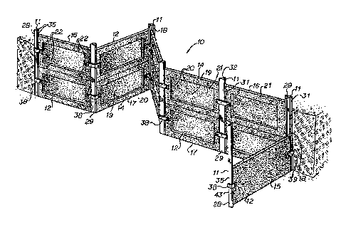
6 Fig. 1 a rPi:aina.ng Wall 10 having seven steel piles I1
mounted uprightly in the ground and ~laven precast concrete
ranpl.s 12 mounted upxightly to the piles 11 and to each
other. Each panol 13 has a front side ld, a hark side i5,
a tap end 16, a bottom end 17 and two side ends 10. The
front aide 14 has a recess 19 defined by a recess floor 21
and perimetral recess walls 20 which arc oriented
approximately 45° to the front side 14 arid recess Iloor 21.
Each panel has four side holes 22 and two end holos 23
extending Completely i:hrough the panel. Each hole has a
jplastlc; sleeve 24 mounted therein.
The piles 1.1. located on the ends of the wall 1o are
.'generally L-shaped angle iron typA piles 28 while ~:hp
intermediate piles located between adjacent panels 12 are
generally T-ahapod or T-bar typo piles 29. The T-shaped
p:i.le5 29 have a face bax 31 and a center bar 32 chtending
generally normal from a mid portion of the face bar 31.
fhe L-shaped piles 28 Yiave two side bars 35 oxinnted
generally normal to each ether.
' The pduels 12 are retained genorally in position by '
outer links 38 and inner links 39. Each link is rigid and
has an elongated Blot 40 adjacent each of its ends. A
thraac3c~d bolt 42 extends through oath slot 40 of the outer
link 30, through the slssvn 24 of a penal hole 22 or 23.
and through each slot 40 of ~ha inner link 39. A nut 43 is
threaded fairly tightly onto c~aah bolt end.
To erect the: retaining wall 10 the piles 11 era first
driven into the ground at dtstances slightly greater than
the length ~t a panel. As bast shown in Fig. 2, two end
member of panels 12 are positioned uprightly between an L
i
3~ ' shaped pile 28 and an adjacent T-ehaped piles 29. One side
end 18 of each panel is positioned between l,he side bars 3~
200~69~
-~ 4
of the L-shaped pile a8 while the other side end 18 is
positioned between the center bar 32 ana l.tie race bar 31
of the T-shaped pile 24. The panel is secured i:n thp 7~-
shaped pile by pivotably mouirlang an outer link 38, fornsed
into the shape of a V, to the~panRJ. and about the L-shaped
pile 28. This is done by extending a bolt 42 through the
link slot d0 adjar_.ent the panel. front sine 14, the sleeved
panel end hole 23, and the link slot 40 adjacent the panel
bark side 15 and threaded a nut 43 onto the bolt end.
Next, another panel 12 is pooitioned between the T-
shaped pile 29 adjacent the first panel and the next
cuccoooive T-shaped pile 29. The panel is positioned se
that each of its end walls 18 i.s located between the center
bar 32 and the face box 31 of a T-shaped piles. The two
jadjac:ent panels are then mounted to each other and to the
pile positioned therabPtcaPan by pi.votably mounting the ends
'ot the outer and inner links 78 and 39 to each panel. Thin
is done by extending the bolts 42 through slots 40 of the
outer link 3~i, the 3leevcd and holca 23 of the panels, and
the slot 40 of the inner link 39 and then threading nuts
43 onto the bolt ends. In turn the other bottom panels of
the wall are p~5itiunsa and mounted in the just described
manners. Once the bottom panels are mounted upper panels
may k~e stacked upon them and mounted to each other and to
th9 piles in the manners just described. fhe wall may
alternatively be constructed one 3cction at a time along
the entire length of the wall by successively forming
vertical stac)ta of panol~.
As shown in Fig. 3, the retaining wall may include
panels With their longer eida oriented vertically instead
of horizontally. When oriented vertically the side holes
22 of the panel are located at substantially the same IRVPI
as the end holes 18 of a hvriz~n tai panel. The vertical
~ panel may be coupled to one or mare horiz~nl:a1 panels as
~ previously described except that Lolts 42 extend through
the vcrtioal panel s side holes 22 rather than its end
20946~~
-5-
holcc 23. A vertical orientation of a panel may be
preferred when t;he width oL a section of the wall between
two p119s 1S Rl~tlc'll t:(7 (1Y 1 ass than some two feet,
The wall may be constructed with laterally adjaoont
S panels oriented at various acute and obtuse angles to each
other a3 shown in both Figs. 1 and 3. In such cases, the
outer arid inner links 38 and 39 are bent or wnt;oured t;o
conform substantially to the angle between the panels.
AS best; shown in Fig. 9~, the new earth retaining walls
may have panels initiaJ.ly mounted at somewhat different
levels as where the terrain is sloping. Al:.o, with thio
wall construction individual panels or individual stacks of '
panels may vertically shift over time ae the adjacent earth
settles and shifts without adversely effecting the
jintogrity of the wall. This important characteristic of
lthe wall is attributed to the panels being movably mounted
to adjacent panels and piles. Each panel or panel stack
may therefore shift without dl5lux-biny oz er.Cecting the
positioning of the laterally adjacent panQls or piles.
Where Lh.is occurs an entirE stack will normally settle as
a unit without a gap heing created between the panel
members of the stack.
several factors contribute to the movability of the
panels. One design factor i3 the elongated .clotE which
allow the panel bolts to shift therein. This, in
combination with the pivotable mounting of the links,
allows the panels to move horizontally or vertically for a
limitod distance. Lateral special tolerance during
mounting or afterwards as the earth seCtles and shifts,
also doss not create gaps in the walls as the piles
themselves still provide wall continuity. The sleeves of
thA panel holes 22 and 23 have an inci.dp diameter.
approxlmalely 1/4 or aw inch larger than the outside
diameter of the shaft of the bolt 42. This al.sn allows the
' panels to move slightly without moving the links. Note
that panels holes 22 and 73 which are not occupied by bolts
2~~469~
4~ function as weep holes.
It should be understood that the retaining wall may
hP constructed of piles formed of a single bar. However,
such is not rocommandod since multiple bar piles, and
eSpeCially the x-shaped piles, have gren~er in ground
stability.
It thus is 5eeai l:hai: a new retaining wall is nou
provided that overcomes prohlams long associated with those
of tlae prior art. 'Though the wall has herein been ~hown
for use in ret2i.ning earth, it may, or couxse, be used in
other applicctions. It should be undorEtood that many
modif5.cations, additions and deletions may be made to i:he
preferred embodiment that has bean illustrated and
described without departure rrom the spixiL and scope of
the invention as set forth in the following claims.