Language selection

Search

Patent 2094717 Summary

Third-party information liability

Some of the information on this Web page has been provided by external sources. The Government of Canada is not responsible for the accuracy, reliability or currency of the information supplied by external sources. Users wishing to rely upon this information should consult directly with the source of the information. Content provided by external sources is not subject to official languages, privacy and accessibility requirements.

Claims and Abstract availability

Any discrepancies in the text and image of the Claims and Abstract are due to differing posting times. Text of the Claims and Abstract are posted:

  • At the time the application is open to public inspection;
  • At the time of issue of the patent (grant).
(12) Patent: (11) CA 2094717
(54) English Title: CONSTANT PRESSURE PERIODONTAL PROBE
(54) French Title: SONDE PERIODONTIQUE A PRESSION CONSTANTE
Status: Expired and beyond the Period of Reversal
Bibliographic Data
(51) International Patent Classification (IPC):
  • A61C 19/04 (2006.01)
(72) Inventors :
  • LEMON, ROBERT J. (United States of America)
  • EVANS, WILLIAM T. (United States of America)
  • CHRISTIAN, ROBERT E. (United States of America)
  • BADER, HERBERT I. (United States of America)
(73) Owners :
  • PROFESSIONAL DENTAL TECHNOLOGIES, INC.
(71) Applicants :
  • PROFESSIONAL DENTAL TECHNOLOGIES, INC. (United States of America)
(74) Agent: KIRBY EADES GALE BAKER
(74) Associate agent:
(45) Issued: 1998-10-13
(86) PCT Filing Date: 1991-09-25
(87) Open to Public Inspection: 1992-04-26
Examination requested: 1993-04-22
Availability of licence: N/A
Dedicated to the Public: N/A
(25) Language of filing: English

Patent Cooperation Treaty (PCT): Yes
(86) PCT Filing Number: PCT/US1991/006994
(87) International Publication Number: US1991006994
(85) National Entry: 1993-04-22

(30) Application Priority Data:
Application No. Country/Territory Date
603,638 (United States of America) 1990-10-25

Abstracts

English Abstract


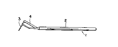
A constant pressure periodontal probe (1) has a probing portion (3) and connected to a handle (2) through a flexing joint
(10). A backing portion (15) extends from the handle adjacent to but spaced away from the probe tip (6) such that a gap (17)
exists between the probe portion (3) and the backing portion (15). As the probing portion (3) is inserted into a pocket between the
tooth and gum, the amount of resistance causes the probe portion (3) to be displaced about the flexible joint (10), closing the gap
between the probing (3) and backing (15) portions. When the probing portion (3) contacts the backing portion (15), a constant
insertion pressure has been reached and a reading is taken to determine the depth of the pocket.Utilizing such a constant pressure
periodontal probe (1) assures that each reading is taken at a set pressure, preventing damaging to the gum tissue and assuring
accurate readings.


French Abstract

Sonde parodontale à pression constante (1) composée d'un élément d'exploration (3) et reliée à un manche (2) par une charnière flexible (10). Un élément de soutènement (15) s'étend du manche adjacent à l'extrémité de la sonde (6) mais non contigu à celle-ci, de façon qu'il existe un espace (17) entre l'élément d'exploration (3) et l'élément de soutènement (15). Lorsque l'élément d'exploration (3) est introduit dans une poche entre la dent et la gencive (10), le degré de résistance fait en sorte que l'élément d'exploration (3) se déplace autour de la charnière flexible (10), comblant ainsi l'espace entre l'élément d'exploration (3) et l'élément de soutènement (15). Lorsque l'élément d'exploration (3) est mis en contact avec l'élément de soutènement (15), une pression constante à l'insertion est obtenue et une lecture est faite afin de déterminer la profondeur de la poche. L'utilisation d'une telle sonde parodontale à pression constante (1) permet de s'assurer que la lecture est faite à une pression fixe; on évite ainsi de blesser la gencive et les lectures sont précises.

Claims

Note: Claims are shown in the official language in which they were submitted.


- 7 -
CLAIMS
1. A constant pressure periodontal probe comprising
a handle, a probing portion extending from the
handle, and a rigid backing portion extending from the
handle adjacent to but spaced away from the probing portion
by a gap, a flexing joint provided in the probing portion,
the flexing joint being a portion of reduced strength to
allow the probing portion to be displaced about the flexing
joint as resistance to insertion increases, the backing
portion providing a stop to limit displacement of the
probing portion, contact between the backing portion and
the probing portion indicating that a desired insertion
pressure has been reached.
2. The probe of Claim 1 wherein the backing
portion has a tip for contacting the probing portion.
3. The probe of Claim 1 wherein the probing
portion has a needle-like tip, a corner, the needle-like
tip extending from the corner, first and second sections
disposed on opposite sides of the joint in an angular
relationship, the first section connected to the corner and
the second section connected to the handle.
4. The probe of Claim 1 wherein the gap between
the backing portion and probing portion corresponds to an
insertion pressure applied to the probe of 20 grams.
5. The probe of Claim 2 further comprising a
partial sphere, disposed on the end of the needle-like tip,
an inwardly curved edge provided on the sphere.
6. The probe of Claim 3 wherein the corner has a
channel, the needle-like tip being locatable in the
channel, the needle-like tip being replaceable.

Description

Note: Descriptions are shown in the official language in which they were submitted.


W';~2/07524 PCT/US91/06994
0~717
CONSTANT PRESSURE PERIODONTAL PROBE
TECHNICAL FIELD
This invention relates to periodontal probes and
more particularly to a constant pressure periodontal probe
which indicates when a desired insertion pressure is
achieved.
BACKGROUND OF THE lN V ~:N'l'ION
Periodontal probes are used to test the depth of
a pocket which exists between a tooth and a gum. The
pocket is formed as a result of progressive gingival
inflammation. Once formed, the periodontal pocket provides
a sheltered environment for pathogenic microbial colonies,
which may cause further connective tissue destruction. The
depth measurement indicates whether periodontal disease is
present and to what extent; the deeper the pocket, the less
attachment there is between the tooth and gum and more
likely it is that treatment is required.
Typical periodontal probes, shown for example in
U.S. Patent numbers 4,768,952, 4,886,454, and 4,764,114,
use a needle-like tip. The tip is inserted until the
bottom of the pocket is reached, with the tester relying on
the resistance to insertion to feel the bottom of the
pocket. The tip usually has markings to indicate the depth
of the pocket. Pocket depths over about three millimeters
indicate that treatment should be undertaken. Two or three
readings may be taken per tooth and a history developed to
note changes in pocket depth to determine if progressive
pocket enlargement is apparent.

W092/07~24 PCT/US91/06~'
~9 ~ 2 -
A problem with periodontal probing is that, to beaccurate, the pressure used to push down the probe tip into
the pocket must be the same for each test. In addition,
the force applied must be less than would cause the tip to
pierce the pocket, damaging the tissue and giving an
erroneous reading. If different pressure is applied at
different locations or during subsequent probing, the
readings will vary and the test results become meaningless.
The World Health Organization has determined that
a pressure of about 20 grams should be used as the standard
insertion pressure. This is the level at which the probe
overcomes the resistance caused by the gum mating with the
tooth, yet prevents the probe tip from piercing the bottom
of the periodontal pocket. This is a very low value
compared to the amount of pressure which could be applied
during insertion and it is very difficult to feel when that
level of pressure has been reached. By monitoring probing
done during a typical examination, it was determined that
testers routinely applied double or triple this amount of
force without being aware of it.
DISCLOSURE OF THE INVENTION
It is an object of the present invention to
provide a constant pressure periodontal probe which pro-
vides an easily identifiable indication that a desired
insertion force has been applied.
It is another object to provided a constant
pressure periodontal probe which is disposable.
It is yet another object to provide a constant
pressure periodontal probe which is integrally molded to
minimize cost.

CA 02094717 1998-04-24
These and other objects of the present invention
are achieved by providing a periodontal probe having a
handle, a probing portion extending from an end of the
handle, and a backing portion, extending from the end of the
handle adjacent to but spaced away from the probe portion.
The probing portion has a needle-like probing tip which may
optionally include markings to indicate depth of insertion.
This tip is connected to the handle through a flexible
joint, preferably shaped and tapered to allow the tip and
arm to flex in an arc about the joint as the resistance to
insertion increases. The backing portion is separated from
the probing portion by a gap, the backing portion providing
a stop to limit the travel of the probing portion. The gap
is of sufficient width such that when the portions touch, a
desired constant pressure is indicated. At that point, the
tester reads the depth of insertion. Such a probe assures
that an accurate reading is taken, and that all subsequent
tests are taken at the same insertion pressure.
Thus, in accordance with the invention, there is
provided a constant pressure periodontal probe comprising a
handle, a probing portion extending from the handle, and a
rigid backing portion extending from the handle adjacent to
but spaced away from the probing portion by a gap, a flexing
joint provided in the probing portion, the flexing joint
being a portion of reduced strength to allow the probing
portion to be displaced about the flexing joint as
resistance to insertion increases, the backing portion
providing a stop to limit displacement of the probing
portion, contact between the backing portion and the probing
portion indicating that a desired insertion pressure has
been reached.
BRIEF DESCRIPTION OF THE DRAWINGS
Fig. 1 is a side view of the constant pressure
probe of the present invention.

CA 02094717 1998-04-24
- 3a -
Fig. 2 is an enlarged sectional view of the probe
of Fig. 1.
Fig. 3 is a cross sectional view of the probe
taken along line 3-3 of Fig. 2.
Fig. 4 is an enlarged front view of the probe of
Fig. 1.
Fig. 5 is an enlarged cross sectional view of the
end of the probe tip.

P CT/ U S 9 ~ 9 4
15 ~ T~PTO ~. 8 FEa IY~2 -
PEA/US
DETAILED DESCRIPTION OF THE INVENTION
Referring to Fig. 1, a constant pressure probe 1
- has a handle 2, a probing portion 3 and a backing portion
4. The handle may be round or shaped to provide effective
hand manipulation of the probe.
The probe is made of plastic or metal, with
plastic preferred as it allows the probe to be disposable.
Among the materials of construction useable with the
present invention are polyethylene, polypropylene, nylon,
polystyrene, polyurethane, polyetherimid (Ultem~), steel,
stainless steel, or combinations thereof. Ultem~ is
preferred as it has good strength properties while being
sufficiently high temperature resistant to allow steriliz-
ation.
Referring to Fig. 2, the probing portion 3 isjoined at junction 5 to the handle 2. The probing portion
3 includes a needle-like tip 6 which extends from a corner
7. The corner 7 has an upwardly extending projection 8,
and is attached through a first rigid section 9 to a
flexing joint 10 through a second rigid section 11 to the
junction 5. The flexing joint 10 provides a focal point
for probe displacement when resistance to insertion is met.
The flexing joint 10 is tapered and shaped to provide the
- weakest point between the sections 9 and 11 such that the
resistance to probing-causes the probe to travel in an arc
about the flexing joint.
Referring to Fig. 3, a cross sectional view of
the flexing joint 10 is shown. The flexing joint has two
opposed flat surfaces 12 and 13~ in the-desired plane of
trave}, with the joint having rounded sides to provide a
somewhat oblong shape. The flat surfaces provide weakening
areas to assure movement in a planar direction in alignment
SUBS~ITUT~ St~T
~US

P~TJUS 91 /06'9g4
1~ R~c'~ P~T~PT,û 2 B FEB 1992 IPEAJU'
73 ~ ~ 4 ~ ~ 7
with the backing portion. This guides the probe to prevent
displacement in an angular direction, to assure contact
with the backing portion. Of course, other shapes and
designs could be use to provide the flexing joint.
Referring again to Fig. 2, the backing portion 4
is joined at an end 14 through the junction 5 to the handle
2. The backing portion 4 has a rigid arm 15 extending
parallel to the first section 9 of the probing portion,
extending adjacent to but spaced away from the probing
portion. Both portions are coplanar and in alignment. The
arm 15 has sufficient rigidity to prevent movement when a
force greater than the desired probing insertion force is
applied against it. This can be adjusted by increasing the
thickness of the arm relative to the thickness of the
probing portion. The backing portion has a tip 16 which is
spaced away from the projection 8 of the probing portion.
Thus, a gap 17 is provided therebetween. The gap 17 is
sized to accommodate movement of the probing portion as the
resistance to insertion causes the probing portion to move
about the joint 10, with contact between the tip 16 and the
projection 8 indicating that the desired pressure has been
reached. Thus, the backing tip 16 provides a stop for
receiving the projection 8.
~- - Referring to Fig. 4, the projection 8 and tip 16
have-tapered sides 18 and~19 respectively. Thus, in the
event that additional probing force is desired, after
contact, the user may slightly twist the handle to flex the
probing portion in an angular direction about the joint 5
and misalign the tip and projection to increase the inser-
tion pressure. Depending on the choice of material, as the
amount of flexing increases, the resistance to the dis-
placement of the probe about the flexible joint increas-
IPEA/US

P(~T/US 91 /06994
15 Rec'd PCT/PT0 ~ 8 FEB 1992
- 6 - ~ ~ ~ 4 ~
es, with the modulus and cross-section of the flexing joint
determining the maximum amount of displacement allowable.
Referring to Fig. 5, the probing tip 6 has a ball
end 20 which comprises a partial sphere 21 with an inward-
ly curved edge 22. The roundness of the sphere allows ease
of insertion of the tip between the gum and tooth, but on
withdrawal, the edge 22 rides against the tooth surface so
that the user may detect if a layer of subgingival calculus
lo has built up on the tooth surface. Thus, as the edge is
pulled across the tooth surface, it may engage the layer
which the user can feel by the halting motion of the probe
during withdrawal.
The probe is preferably produced as a unitary
structure to minimize cost and allow mass production by
molding. However, it is contemplated that the probe tip
may be separately produced and be removable from the corner
to allow replacement. For example, the corner 7 may
include a channel sized to accept an end of a separable
needle-like tip, with suitable means provided for locking
the tip in place. Thus, such a modification is within the
scope of the present invention.
While preferred embodiments of the present
- -lnvention have been shown and described, it will be under-
stood by those skilled-in~the art that various changes or
modifications could be made without varying from the scope
of the present invention.
We Claim:
SUBSTITIJTE SHEET
)S

Representative Drawing
A single figure which represents the drawing illustrating the invention.
Administrative Status

2024-08-01:As part of the Next Generation Patents (NGP) transition, the Canadian Patents Database (CPD) now contains a more detailed Event History, which replicates the Event Log of our new back-office solution.

Please note that "Inactive:" events refers to events no longer in use in our new back-office solution.

For a clearer understanding of the status of the application/patent presented on this page, the site Disclaimer , as well as the definitions for Patent , Event History , Maintenance Fee  and Payment History  should be consulted.

Event History

Description Date
Inactive: Reversal of expired status 2012-12-02
Time Limit for Reversal Expired 2011-09-25
Letter Sent 2010-09-27
Inactive: Entity size changed 2002-10-02
Grant by Issuance 1998-10-13
Letter Sent 1998-07-24
Amendment After Allowance Requirements Determined Compliant 1998-07-24
Inactive: Amendment after Allowance Fee Processed 1998-04-24
Pre-grant 1998-04-24
Inactive: Final fee received 1998-04-24
Amendment After Allowance (AAA) Received 1998-04-24
Letter Sent 1998-02-27
Notice of Allowance is Issued 1998-02-27
Inactive: Status info is complete as of Log entry date 1998-02-24
Inactive: Application prosecuted on TS as of Log entry date 1998-02-24
Inactive: Approved for allowance (AFA) 1998-02-06
Inactive: IPC removed 1998-02-06
Inactive: First IPC assigned 1998-02-06
Inactive: IPC assigned 1998-02-06
All Requirements for Examination Determined Compliant 1993-04-22
Request for Examination Requirements Determined Compliant 1993-04-22
Application Published (Open to Public Inspection) 1992-04-26

Abandonment History

There is no abandonment history.

Maintenance Fee

The last payment was received on 1998-07-09

Note : If the full payment has not been received on or before the date indicated, a further fee may be required which may be one of the following

  • the reinstatement fee;
  • the late payment fee; or
  • additional fee to reverse deemed expiry.

Patent fees are adjusted on the 1st of January every year. The amounts above are the current amounts if received by December 31 of the current year.
Please refer to the CIPO Patent Fees web page to see all current fee amounts.

Fee History

Fee Type Anniversary Year Due Date Paid Date
MF (application, 6th anniv.) - small 06 1997-09-25 1997-06-11
1998-04-24
Final fee - small 1998-04-24
MF (application, 7th anniv.) - small 07 1998-09-25 1998-07-09
MF (patent, 8th anniv.) - small 1999-09-27 1999-08-18
MF (patent, 9th anniv.) - small 2000-09-25 2000-09-25
MF (patent, 10th anniv.) - small 2001-09-25 2001-07-04
MF (patent, 11th anniv.) - standard 2002-09-25 2002-09-25
MF (patent, 12th anniv.) - standard 2003-09-25 2003-07-15
MF (patent, 13th anniv.) - standard 2004-09-27 2004-09-10
MF (patent, 14th anniv.) - standard 2005-09-26 2005-06-28
MF (patent, 15th anniv.) - standard 2006-09-25 2006-08-11
MF (patent, 16th anniv.) - standard 2007-09-25 2007-08-08
MF (patent, 17th anniv.) - standard 2008-09-25 2008-08-11
MF (patent, 18th anniv.) - standard 2009-09-25 2009-08-13
Owners on Record

Note: Records showing the ownership history in alphabetical order.

Current Owners on Record
PROFESSIONAL DENTAL TECHNOLOGIES, INC.
Past Owners on Record
HERBERT I. BADER
ROBERT E. CHRISTIAN
ROBERT J. LEMON
WILLIAM T. EVANS
Past Owners that do not appear in the "Owners on Record" listing will appear in other documentation within the application.
Documents

To view selected files, please enter reCAPTCHA code :


To view images, click a link in the Document Description column. To download the documents, select one or more checkboxes in the first column and then click the "Download Selected in PDF format (Zip Archive)" or the "Download Selected as Single PDF" button.

List of published and non-published patent-specific documents on the CPD .

If you have any difficulty accessing content, you can call the Client Service Centre at 1-866-997-1936 or send them an e-mail at CIPO Client Service Centre.


Document
Description 
Date
(yyyy-mm-dd) 
Number of pages   Size of Image (KB) 
Description 1997-12-28 6 259
Claims 1997-12-28 1 45
Representative drawing 1998-10-08 1 2
Description 1998-04-23 7 274
Description 1994-03-25 6 244
Drawings 1994-03-25 1 23
Abstract 1995-08-16 1 65
Claims 1994-03-25 1 42
Commissioner's Notice - Application Found Allowable 1998-02-26 1 165
Maintenance Fee Notice 2010-11-07 1 171
Correspondence 1998-04-23 1 51
Correspondence 1993-11-15 1 19
Fees 1995-06-11 1 48
Fees 1996-06-16 1 61
Fees 1994-07-07 1 41
Fees 1993-04-21 1 52
Correspondence 1993-10-31 4 90
Examiner Requisition 1996-03-28 1 65
Prosecution correspondence 1996-07-16 1 44
International preliminary examination report 1993-04-21 15 551