Note: Descriptions are shown in the official language in which they were submitted.
i
002-923866-NA
Tool Handles Having Wear Indication
by: Mark W. Blake:;
Christopher G. Chadbourne; and
Gennaro L. Pecora
BACKGROUND OF THE IN4'ENTION
1. Field of the Invention
The present invention relates to hand operated
tools and, more particularly, to handles for such
tools.
2. Prior Art
Various different handles are known in the prior
art relating to hand operated tools. U.S. Patent
3,182,485 discloses handles as fiberglass rods.
U.S. Patent 3,872,528 discloses '.handles of cast or
fcrged metal. U.S. Patent 3,330,148 discloses a
gaging mechanism for a compression tool. As can be
seen from U.S. Patent 3,330,148,. a problem exists
with certain types of hand oper<~ted tools in that
the tools have to be adjusted in order to maintain
the tool in precise alignment.
It is an object of the present invention to provide
a new and improved handle for a hand operated tool.
CA 02094865 2001-03-22
2
SUMMARY OF THE INVENTION
In accordance with a first aspect of the present
invention, there is provided a hand operated
compression tool comprising:a working head; and a pair
of handles operably connected to each other and to the
working head, the handles each comprising a one-piece
polymer member substantially identical to each other
and merely reversed relative to each other in order to
l0 mate, the handles further comprising means for
indicating wear of the handles at their connection to
each other including a link connected to each handle
having a marking and at least one of the handles
having a marking, the markings being adapted to
indicate excessive wear of the handles.
In accordance with another aspect of the present
invention, there is provided a compression tool handle
for use with a second handle and a working head of a
2o compression tool, the handle comprising: a hand grip
section at a first end; a shaft section extending from
the hand grip section; and a connection section at a
second end of the shaft section, the connection
section having at least one wear surface adapted to
wear away during use of the handle, a first recess for
receiving a portion of a first link, a second recess
for receiving a portion of a second link, and a hole,
the sides of the hole acting as the wear surface, the
handle being comprised of a single polymer member and
3o having a hamaphrodidic design such that two of the
handles can be connected to each other in reverse
fashion, and further comprising a marking on the side
of the connection section adapted to indicate
excessive wear of the wear surface.
CA 02094865 2001-03-22
3
In accordance with a third aspect of the present
invention, there is provided a method of manufacturing
a hand operated tool, the method comprising steps of:
providing two handles, each handle having means for
connecting a portion of a working head thereto, each
handle being comprised of a hamaphrodidic one-piece
polymer member; connecting the two handles to each
other to provide for pivotal motion therebetween, the
1o connection comprising a member being positioned in a
hole of each handle, a side of the hole forming a wear
surface, and a portion of each handle having a surface
perpendicular to its hole that is adapted to slide
substantially freely upon a cooperating surface of the
other handle; and connecting two strengthening links
to the handles, one of the links on each side of the
handles, the links and handles comprising indicia to
indicate excessive wear of the wear surfaces.
BRIEF DESCRIPTION OF THE DRAWINGS
The foregoing aspects and other features of the
invention will become more apparent upon reading of
the following description of a preferred embodiment
thereof, given for the purpose of illustration only in
connection with the accompanying drawings, wherein:
Fig. 1 is a plan front view of a hand operated
compression tool incorporating features of the present
invention.
Fig. 2 is a plan front view of one of the handles used
in the tool shown in Fig. 1.
CA 02094865 2001-03-22
3a
Fig. 3 is a partial exploded perspective view of a
connection end of the handles shown in Fig. 1.
DETAILED DESCRIPTION OF THE PREFERRED EMBODIMENT
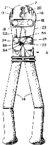
Referring to Fig. l, there is shown a plan front view
of a compression tool or crimping tool 10, the
~94~fi~
4
rear view being a mirror image ithereof. Although
the present invention will be described with
reference to the single embodiment shown in the
drawings, it should be understood that the present
invention may be embodied in many alternate forms
of embodiment. In addition, any suitable size,
shape, or type of elements or materials may be used
as further understood below.
The tool 10 generally comprises a working head 12
and two handles 14. The working head 12 is
preferably made of metal wii:h two pivotally
connected jaws 16, 17, pivoted at: pivot location 19
and connected by two plates 18 (only one of which
is shown) on opposite sides of the jaws. The jaws
16, 17 each have two compression areas 20 and 21,
for crimping a connector~to an electrical wire, and
a connection end 22 for connecting each of the jaws
to one of the handles 14. The connection end 22 of
each jaw has a hole for receiving a bolt 24 that
operably connects the jaws to a. handles 14. The
working head 12 is substantially the same as the
working head used in the HYTOOL MD6-8 manufactured
by Burndy Corporation, Norw<~lk, Connecticut.
However, any suitable type of woz-king head could be
used.
I~~ the embodiment shown, the pair of handles 14 are
hamaphrodidic: i.e: identical to each other, but
orientated reverse to each other.°. The handles 14
are pivotally connected to each other by a bolt 26
and two strengthening links 23 (only one of which
is shown). The links 23 are.preferrably made of
5
metal. However, any suitable ~oaaterial could be
used. As can be seen in Fig. 3, each link 23 has a
plate-like shape with two holes. However, any
suitable type of connection could be provided:
Referring also to Figs. 2 and :3, each handle 14
generally comprises a hand grip section 28 at a
first end, a shaft section 30, and a connection
section 32 at a second end. 'the handle 14 is
preferably made of a dielectric: polymer material
and provided as a single one-piece member. The
hand grip section 28 has a bobbed grip end 60, and
knurled finish 64. The shaft section 30 has a stop
34 adapted to contact the stop o~n the other handle
to limit a range of motion of the handles, and
dielectric lengthening ribs X62. However, any
suitable type of hand grip section or shaft section
could be provided. The connecition section 32 of
each handle 14 generally comprises three projecting
portions 36, 37, 38. The first projecting portion
36 has a leading surface 40 that is curved and a,
hole 42. The first projecting portion 36 only
extends across about one-half the thickness of the
handle 14 and, thus, a first recessed area 44 is
established. The recessed area 44 has a surface 46
generally parallel to the center axis of the hole
42. The second and third projecting portions 37
and 38 have a slot 48 therebetween. The slot 48 is
provided to receive the connection end 22 of one of
the jaws 16, 17. The projection 3? only extends
about three-fourths the thickness of projection 38.
Thus, a second recessed area 39 is established that
extends the width of surface 52. Projection 36 has
a perpendicular surface 49 that is recessed
,,. 6
relative to side 56 such that this surface 49 and
surface 36 of the two handles can sit flush, or in
the same plane with each other, on both sides of
the handles when the handles are .assembled. Holes
50, 51 are provided in each handle such that one of
the bolts 24 can be used to fa.xedly attach the
connection end 22 of each jaw of the working head
12 to the portions 37, 38 of each handle. However,
any suitable means of connecting the working head
12 to the handles 14 could be provided.
Ire the embodiment shown, the first side 56 of each
handle 14 has indicia or markings 54 about the edge
of the surface 47. In the embodiment shown,
indicia 54 merely comprises a molded polygonal
shape of a given width on first side 56. However,
any suitable type of indicia or markings could be
used. A second indicia or marking 58 is provided
on link 23 which sits on surfaces 39 and 49 of the
assembled tool. In an alternate embodiment,
however, only one side of each handle need have
indicia. In addition, any suitable type of handle
connection section could be provided.
As noted above, the pair of handles 14 are
identical and one of the handles is merely reversed
relative to the other in order to mate. As can be
described best with reference to Fig. 3, the first
projecting portions 36 of each handle are merely
placed adjacent each other in the other handle s
recessed area 44, their holes 42 aligned, links 23
are laid onto surfaces 39 and 49 with all the
appropriate holes aligned, and bolt 26 (see Fig. 1)
W
is inserted into the holes 42 to pivotally attach
the two handles 14 to each other. The connection
ends 22 of the jaws are then located in areas 48 of
the two handles and the two bolts 24 are then
inserted into the appropriate holes of the handles,
jaws and links to complete assembly of the tool 10.
One of the major problems with the prior art is
that the tools, due to the high forces that they
are subjected to, must be periodically checked for
misalignment of the handles relative to each other
and, adjusted if necessary. The present invention
is_ adapted to do away with the task of having ~ to
periodically adjust the alignment: of the handles.
This is accomplished by merely making the handles
14 of a relatively inexpensive material with a
relatively inexpensive manufacturing cost and,
providing suitable means to indicate or signal when
excessive misalignment occurs. When excessive
2p misalignment occurs, the handles are merely
replaced. In the embodiment shown, the handles 14
are comprised of identical one-piece polymer
members that can be molded an a relatively
ine-:~pensive manufacturing proces:~. The bolts 24
and 26 bear against the two hand:Les 14 inside the
surfaces of the holes 42, 50 and 51. Because the
handles 14 are made of a polymer material, over
time and use the surfaces inside the holes 42, 50
and 51 are adapted to wear away due to the
frictional forces and high compressive loads
between the parts during crimping. Because the
surfaces 42, 50 and 51 have been provided to wear
away during prolonged use of the tool 10, indicia
a~~~fi~
54 and 58 have been provided such that, when the
amount of wear of surfaces 42, 50 and 51 reaches or
exceeds a predetermined amount of wear, the indici:a
54 and 58 become misaligned. Thus, when the
indicia 54 and 58 become misaligned, the user knows
that the handle or handles 14 need to be replaced
in order to allow the tool 10 to continue to obtain
a good grip of a connector on a conductor, or other
compression operation: i.e.: t:o operate within
acceptable performance characteristics. Thus, the
handles 14 of the present invention never need to
be adjusted. Upon misalignment of indicia 54 and
58, the handle or handles are. merely replaced.
This eliminates the need for alignment gauges and
equipment. The single handle design (both handles
have the same design) of the handles 14, makes
inventory and replacement much simpler than the two
handle design (each handle having a different
design) in the prior art. In addition, the
one-piece design of handles 14 can be much less
expensive than prior art handless comprised of an
assembly of a multitude of different parts. As
noted above, because handle 14 is made of a
non-conductive polymer material, a user is afforded
some additional measure of safei~y, over devices in
the prior art, from inadvertent electrical shock
through the handles 14. The prior art used a
mufti-piece handle assembly with a non-conductive
handle section and a metal connection section to
the working head. The use of: a molded polymer
material allows special shapes and features to be
integrally formed with the handle 14 without any
significant increase in cost,- such as the bobbed
9
grip end 60, knurled finish 64 in the hand grip
section 28, and also such as the dielectric
lengthening ribs 62 at the shaft section.
From the above description of th.e embodiment shown
in the drawings, variations of embodiments of the
invention should be obvious. For example, the
handles 14 need not be identical. Each handle
could be comprised of an assembly of parts or
multiple types of materials. The wear surfaces
could be made as replaceable inserts or the handle
connection sections could be provided as
replaceable inserts. The handle could also be made
with hollow sections or longitudinal grooves to
reduce weight, but nonetheless. retain a strong
structural integrity. Rather than the use of
indicia on the handles or visual indication of
wear, the handles could be provided with audio or
other sensory perceived signals, such as the feel
of the tool during crimping.
Let it be understood that the foregoing description
is only illustrative of the invention. Various
alternatives and modifications can be devised by
_ 25 those skilled in the art without. departing from the
spirit of the invention. Accordingly, the present
invention is intended to embrace all such
alternatives, modifications and variances which
fall within the scope of the appended claims.