Language selection

Search

Patent 2094967 Summary

Third-party information liability

Some of the information on this Web page has been provided by external sources. The Government of Canada is not responsible for the accuracy, reliability or currency of the information supplied by external sources. Users wishing to rely upon this information should consult directly with the source of the information. Content provided by external sources is not subject to official languages, privacy and accessibility requirements.

Claims and Abstract availability

Any discrepancies in the text and image of the Claims and Abstract are due to differing posting times. Text of the Claims and Abstract are posted:

  • At the time the application is open to public inspection;
  • At the time of issue of the patent (grant).
(12) Patent: (11) CA 2094967
(54) English Title: COMPOSITE ROAD SAFETY SLIP RAILS MADE FROM METAL AND REINFORCED ROUND WOOD AND THEIR METHODS OF MANUFACTURE
(54) French Title: GLISSIERES DE SECURITE COMPOSITES FABRIQUEES AVEC DES PIECES METALLIQUES ET DE BOIS RONDES, ET METHODE DE FABRICATION
Status: Expired and beyond the Period of Reversal
Bibliographic Data
(51) International Patent Classification (IPC):
  • E01F 15/00 (2006.01)
  • E01F 15/04 (2006.01)
(72) Inventors :
  • DUYCK, DANIEL (France)
  • DE MAUSSION, JACQUES (France)
(73) Owners :
  • DANIEL DUYCK
  • JACQUES DE MAUSSION
(71) Applicants :
  • DANIEL DUYCK (France)
  • JACQUES DE MAUSSION (France)
(74) Agent: OSLER, HOSKIN & HARCOURT LLP
(74) Associate agent:
(45) Issued: 2001-08-28
(22) Filed Date: 1993-04-27
(41) Open to Public Inspection: 1993-10-31
Examination requested: 2000-02-09
Availability of licence: N/A
Dedicated to the Public: N/A
(25) Language of filing: English

Patent Cooperation Treaty (PCT): No

(30) Application Priority Data:
Application No. Country/Territory Date
92 05 540 (France) 1992-04-30

Abstracts

English Abstract


Composite slip rails for road safety made from round wooden bars reinforced
with iron and comprising posts made from sectional iron and supporting each
one a
spacer carrying a horizontal guard rail consisting of previously slotted round
wooden beams reinforced with embedded metal fishplates providing for the
cohesion of the wood and the connection of the elements.


Claims

Note: Claims are shown in the official language in which they were submitted.

CLAIMS:
1. A composite wooden-metal safety slip rail comprising at least one
horizontal guide rail fastened to a metal support, said at least one guide
rail
consisting of cylindrical round wooden billets assembled end to end by
fishplates
which are connected to each other by bolts which extend through said
fishplates and
ends of said billets in a horizontal diametral plane of said billets, wherein
the
improvement consists in that said billets are reinforced on a rear side face
by a U-
shaped section embedded into said billets and are spaced from said metal
support
by a spacer consisting of a wooden cylinder.
2. A safety slip rail according to claim 1, wherein said U-shaped section is
embedded in said billets over a width equal to one third of the diameter of
said billets
to provide for diametral and longitudinal cohesion of the wood.
3. A safety slip rail according to claim 1, wherein the connecting fishplates
are
made fast to the U-shaped section by welding and made fast to said billets by
a
plurality of bolts.
4. A wooden safety slip rail according to claim 1, further comprising
elongated
holes in said fishplates, one of said bolts providing a connecting axis
between a
respective one of said billets and said metal support to enable rotation of
said
respective one of said billets for the mounting of the slip rails with their
ends buried
into the ground.
5. A safety slip rail according to claim 1, wherein said wooden cylinder of
said
spacer is hooped with a galvanized iron ring, further comprising an additional
bolt
extending through said iron ring for connecting said wooden billets through
said
fishplates to said metal support.
6. A composite safety slip rail comprising at least one horizontal guide rail
fastened to a metal support system, said at least one guide rail comprising a
plurality
of elongate wooden billets, fishplates for connecting ends of adjacent ones of
said
billets, fastening means for connecting said fishplates to said billets, the
improvement comprising
a U-shaped section embedded into a rear face of said billets for reinforcing
said billets, and

retaining means for retaining said billets at a distance from said metal
support
system.
7. The safety slip rail of claim 6, wherein said fastening means comprise
bolts
extending through apertures in said fishplates and apertures in said billets.
8. The safety slip rail of claim 6, wherein one of said fishplates is fixed on
said
rear face at each end of said billets to said U-shaped section.
9. The safety slip rail of claim 8, wherein said retaining means comprise a
wooden cylinder intermediate to said metal support system and said wooden
billets,
said wooden cylinder having an aperture therein, and a bolt extending through
said
metal support system, said aperture in said wooden cylinder and apertures in
said
fishplates arranged on said rear face of said billets.
10. The safety slip rail of claim 8, wherein an additional one of said
fishplates
connects a pair of adjacent ones of said billets at a front face of said
billets, said
additional fishplate comprising elongated holes.
11. The safety slip rail of claim 10, wherein said fastening means comprise
bolts extending through said elongated holes in said additional fishplate and
said
billets, said bolts providing a connecting axis to enable rotation of said
pair of
adjacent billets relative to one another.

Description

Note: Descriptions are shown in the official language in which they were submitted.


CA 02094967 2001-O1-11
1
The present invention relates to safety slip rails made from round or
cylindrical wood adapted to be placed in all the places where vehicles are
likely to
move deliberately or accidentally away from the tracks or traffic lanes which
are
assigned to them, in particular along roads and motorways or turnpike roads or
at
the borders of car parks and parking lots. The technical field involved
therefore is
the one of the manufacture or building of road safety devices.
A known system is disclosed in the French patent of invention publication

2, 663, 968.
In accordance with an embodiment of the present invention there is provided
l0 a composite wooden-metal safety slip rail comprising at least one
horizontal guide
rail fastened to a metal support. The at least one guide rail consists of
cylindrical
round wooden billets assembled end to end by fishplates which are connected to
each other by bolts which extend through the fishplates and ends of the
billets in a
horizontal diametral plane of the billets. The billets are reinforced on a
rear side
face by a U-shaped section embedded into the billets and are spaced from the
metal
support by a spacer consisting of a wooden cylinder.
In accordance with another embodiment of the present invention there is
provided a composite safety slip rail comprising at least one horizontal guide
rail
fastened to a metal support system. The at least one guide rail comprises a
plurality
20 of elongate wooden billets, fishplates for connecting ends of adjacent ones
of the
billets, fastening means for connecting the fishplates to the billets.
Additionally, a
U-shaped section embedded into a rear face of the billets for reinforcing the
billets,
and retaining means are provided for retaining the billets at a distance from
the
metal support system.
It is feature of preferred embodiments of the present invention to provide
guard rails made from round or cylindrical wooden beams or balks reinforced
with
embedded iron advantageously combining the complementary properties of these
two materials, of iron-bound or hooped wooden spacers as well as a method of
mounting and of manufacture which increases the reliability of the known
systems

CA 02094967 2001-O1-11
1a
and substantially decreases the manufacturing, transport and working costs. It
adapts itself advantageously to all mounting situations: corners, hill tops,
rail ends.
The problems to be solved are the following:
1. Wood is a heterogeneous natural material likely to exhibit points of lesser
strength and under the shock of a vehicle, there is little bending but it may
break.
On the contrary the coefficient of friction between iron and wood is very
great and
this is a property usable with advantage for braking the vehicles.
2. The metal supports or holders are anaesthetic or homely.
l0 3. The metal supports should be spaced from the guard rail to avoid the
shock
with the vehicle. A spacer therefore is necessary.
4. With the known methods the mounting operations are difficult and make
use of multiple parts. It is therefore necessary to simplify the mounting and
to make
it versatile.
To solve these problems, the following solutions have been found:
30

~0~~~~'~
2
1. The guard rails are reinforced on their sides opposite from the road by a
sectional iron embedded or set in the wooden guard rail. The flanges of the
section
are accommodated within two slots parallel to the center line axis of the
guard rail
and thus are invisible, i.e. hidden.
2. The spacer consists of a round or cylindrical wood arranged vertically
between the metal support and the guard rail. In this manner the support is
concealed but the spacer ends at 5 cm from the ground to avoid any risk of
becoming rotted. For the same grounds the top end is cut slantwise or askew.
3. To avoid hindering or impeding the slipping of the vehicle along the slip
rail, the spacer may turn round the center line axis of the fastening bolt.
The
structure is reinforced with a galvanized metal hoop to avoid any risk of
projection.
4. To facilitate the mounting, those metal fastening butt-straps or fishplates
which are opposite from the road are made fast to an embedded sectional iron
and
mounted in the workshop or factory. All the butt-straps or fishplates are
provided
with elongated holes making the mounting possible in any situations
whatsoever. If
need be, the elements of the horizontal guard rail will have a length of two
or four
metres. They may also be mounted onto existing supports in replacement of
metal
safety slip rails without changing the support and possibly without changing
the
existing metal spacer.
The safety device according to the invention may be put in place with the
equipments available in those enterprises which are usually laying or
installing
metal slip rails without any particular training of the staff.
The device comprises a limited number of standard parts : ...
- standard metal posts,
- wooden spacers according to the invention or standard metal spacers,
- guard rails according to the invention with a length of four metres for
straight
lines and corners or of two metres for special uses and sharp corners,

~~3~4~~'~
3
- fastening bolts of the TRCC 16 x 200 model with shouldered or collar nuts or
with nuts and wide washers,
- short connecting butt-straps or fishplates towards the road side.
The invention will be better understood and further objects, characterizing
features, details and advantages thereof will appear more clearly as the
following
explanatory description proceeds with reference to the accompanying
diagrammatic
drawings given by way of non-limiting example only, illustrating a presently
preferred specific embodiment of the invention and in which
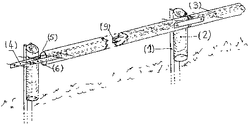
- figure 1 is a perspective view of the most current mounting of a safety slip
rail according to the invention ;
- figure 2 shows an element of horizontal guard rail with a length of four
metres with its characterizing features as well as the connecting fishplate ;
- figure 3 shows the galvanized iron-bound or hooped wooden spacer (2) ;
- figure 4 shows front, bottom and sectional views, respectively, of the
mounting of a guard rail (3) and of the spacer (2) onto the support ( 1 ) ;
- figure 5 shows the mounting of one safety slip rail end with one end driven
into the ground.
Figure 1 is a perspective view of a slip rail section according to the
invention
which consists of galvanized iron posts or uprights ( 1 ) according to the
models
approved by the engineering road and motorway departments, carrying a pre-
impregnated cylindrical wooden spacer hooped with galvanized iron and itself
supporting a horizontal guard rail consisting of cylindrical reinforced wooden
elements previously machined, pre-impregnated and previously mounted in the
workshop or factory, which are assembled end to end by fishplates (4), (5),
(6).
Figure 2 shows the detail of each one of the standard elements of guard rail
such as it leaves the .manufacturing plant, ready to be mounted on the
building site.
Each one of the elements according to the invention consists of a wooden
cylinder

2~~~~~~
4
(3) grooved with two longitudinal slots which are housing in embedded
relationship
both flanges of a sectional iron (9) made fast as by welding to the fishplates
(4) and
(5) ; this metal assembly is secured to the wooden cylinder (3) by two bolts
(10) of
the TRCC 16 x 200 type advantageously mounted in the workshop. The width of
the U-shaped section should be one third of the diameter of the guard rail.
Figure 3 shows the detail of each one of the spacers (2) consisting of a
vertical
wooden cylinder cut at its top part according to a bevel shape in order to
allow rain
water to flow off and hooped or bound with a galvanized iron ring 8. During
mounting, the tightening or clamping effect of this collar will reinforce the
cohesion
of the wooden cylinder and avoid the projections in case of bursting or
splintering
under an impact. The height is designed according to the invention to avoid
the
contact with the ground.
All the wooden parts are processed after having been machined and prior to
the mounting by injections of salts of the CCA type, class 4 according to the
French
standard NF B 50-100.
Each one of the guard rail elements thus described should be made fast to the
following one, to the support 1 and to the spacer 2 according to the mounting
depicted on figure 4 by TRCC bolts 7, 10 and 11 with a diameter of 16 mm. The
elongated holes in the fishplates 4, 5 and 6 depicted on figure 2 allow the
adjustement according to the ground, according to the curves or bends of the
road
carriageway and according to the positions of the metal supports.
The possible rotation about the axis of connection 11 constituted by the TRCG
bolt assembling the support 1, the spacer 2, the fishplate 4 of a horizontal
guard rail
element and the fishplate 5 of the next element advantageously allows the
provision
of the slip rail ends without any modification according to the description
which has
been made thereof with reference to figure 5.

Representative Drawing
A single figure which represents the drawing illustrating the invention.
Administrative Status

2024-08-01:As part of the Next Generation Patents (NGP) transition, the Canadian Patents Database (CPD) now contains a more detailed Event History, which replicates the Event Log of our new back-office solution.

Please note that "Inactive:" events refers to events no longer in use in our new back-office solution.

For a clearer understanding of the status of the application/patent presented on this page, the site Disclaimer , as well as the definitions for Patent , Event History , Maintenance Fee  and Payment History  should be consulted.

Event History

Description Date
Inactive: Agents merged 2013-10-16
Inactive: Reversal of expired status 2013-10-09
Time Limit for Reversal Expired 2013-04-29
Letter Sent 2012-04-27
Inactive: IPC from MCD 2006-03-11
Grant by Issuance 2001-08-28
Inactive: Cover page published 2001-08-27
Pre-grant 2001-05-23
Inactive: Final fee received 2001-05-23
Notice of Allowance is Issued 2001-02-27
Letter Sent 2001-02-27
Inactive: Approved for allowance (AFA) 2001-01-29
Amendment Received - Voluntary Amendment 2001-01-11
Inactive: S.30(2) Rules - Examiner requisition 2000-10-30
Inactive: Application prosecuted on TS as of Log entry date 2000-03-09
Letter Sent 2000-03-09
Inactive: Status info is complete as of Log entry date 2000-03-09
Request for Examination Requirements Determined Compliant 2000-02-09
All Requirements for Examination Determined Compliant 2000-02-09
Application Published (Open to Public Inspection) 1993-10-31
Small Entity Declaration Determined Compliant 1993-04-27

Abandonment History

There is no abandonment history.

Maintenance Fee

The last payment was received on 2001-04-23

Note : If the full payment has not been received on or before the date indicated, a further fee may be required which may be one of the following

  • the reinstatement fee;
  • the late payment fee; or
  • additional fee to reverse deemed expiry.

Patent fees are adjusted on the 1st of January every year. The amounts above are the current amounts if received by December 31 of the current year.
Please refer to the CIPO Patent Fees web page to see all current fee amounts.

Fee History

Fee Type Anniversary Year Due Date Paid Date
MF (application, 5th anniv.) - small 05 1998-04-27 1998-03-24
MF (application, 6th anniv.) - small 06 1999-04-27 1999-03-24
Request for examination - small 2000-02-09
MF (application, 7th anniv.) - small 07 2000-04-27 2000-04-03
MF (application, 8th anniv.) - small 08 2001-04-27 2001-04-23
Final fee - small 2001-05-23
MF (patent, 9th anniv.) - small 2002-04-29 2002-04-19
MF (patent, 10th anniv.) - small 2003-04-28 2003-04-15
2004-04-16
MF (patent, 11th anniv.) - small 2004-04-27 2004-04-16
MF (patent, 12th anniv.) - small 2005-04-27 2005-04-25
2006-04-25
MF (patent, 13th anniv.) - small 2006-04-27 2006-04-25
MF (patent, 14th anniv.) - small 2007-04-27 2007-04-12
MF (patent, 15th anniv.) - standard 2008-04-28 2008-04-25
MF (patent, 16th anniv.) - small 2009-04-27 2009-04-21
MF (patent, 17th anniv.) - small 2010-04-27 2010-04-22
MF (patent, 18th anniv.) - small 2011-04-27 2011-04-17
Owners on Record

Note: Records showing the ownership history in alphabetical order.

Current Owners on Record
DANIEL DUYCK
JACQUES DE MAUSSION
Past Owners on Record
None
Past Owners that do not appear in the "Owners on Record" listing will appear in other documentation within the application.
Documents

To view selected files, please enter reCAPTCHA code :


To view images, click a link in the Document Description column. To download the documents, select one or more checkboxes in the first column and then click the "Download Selected in PDF format (Zip Archive)" or the "Download Selected as Single PDF" button.

List of published and non-published patent-specific documents on the CPD .

If you have any difficulty accessing content, you can call the Client Service Centre at 1-866-997-1936 or send them an e-mail at CIPO Client Service Centre.


Document
Description 
Date
(yyyy-mm-dd) 
Number of pages   Size of Image (KB) 
Abstract 1994-03-11 1 14
Claims 1994-03-11 4 95
Drawings 1994-03-11 4 83
Description 1994-03-11 4 187
Description 2001-01-10 5 217
Claims 2001-01-10 2 82
Representative drawing 1999-02-21 1 9
Representative drawing 2001-08-13 1 11
Reminder - Request for Examination 1999-12-29 1 119
Acknowledgement of Request for Examination 2000-03-08 1 178
Commissioner's Notice - Application Found Allowable 2001-02-26 1 164
Maintenance Fee Notice 2012-06-07 1 172
Fees 2003-04-14 1 46
Correspondence 2001-05-22 1 60
Fees 2001-04-22 1 70
Fees 1999-03-23 1 65
Fees 2002-04-18 1 64
Fees 1998-03-23 1 61
Fees 2000-04-02 1 59
Fees 2004-04-15 1 51
Fees 2005-04-24 1 44
Fees 2006-04-24 1 44
Fees 2007-04-11 1 50
Fees 2008-04-24 1 39
Fees 2009-04-20 1 40
Fees 2010-04-21 1 38
Fees 1997-03-18 1 76
Fees 1996-03-25 1 62
Fees 1995-03-27 1 67