Note: Descriptions are shown in the official language in which they were submitted.
'~092/08224 PCT/GB91/01850
,,J,j, ,
r2ticr c~ntrcl c~--t~ ple
ln~utC
F~slc Or Ir~G~tl~r
The invention relates to a system for activel~ controllin~
vibration. In common with pre~ious methods it useC multiple
actuators and sensors, but the improved method dri~es the
ac~uators using output wave generator~ each of which is
responsi~G to at least two input signals. In particuler,
unlike pre~ious methods, the invention can be applied to the
control o~ vibration from multiple source_ irrespective of
lC the degree of correlation between the sources.
Background to the Invention
In the following the use of the word vibration shall include
sound and other similar linear disturbances.
There have been many publications relating to the active
control of vibration in solids and in fluids. They use one -
or more actuatorC to produce secondary vibration that tends
2C to cancel an unwanted vibration in some region~ Sensors in
this region produce signalc representative of the residual
vibration. These signals (the residual si~nals) are used in
a control system together with input signals to adjust the
signals sent to the actuators.
Active control systems can be broadly categorised according
to the type of input signals used. The first type uses
~nput signals which are both time and amplitude related to
the primary vibration or the combination of both primary
30 and Qecondary vibration. The second type ,uses input signals
which are time related to the primary vibration but contain
no amplitude information.
SUE3STITUTE SHE~
.
. -
~ . ., ... . . .. , ~ .. . .
W092J08224 ~ v~J~ ~ PCT~GB91/018
This second type of system is usually used for
controlling periodic or tonal vibrations and an
example is described in UK patent 1,577,322 (Active
Attenuation of Recurring Sounds, G.B.B Chaplin).
When there is more than one source of vibration it is
sometimes possi~le to use one control system each
source, provided that the sources are uncorrelated
with each other.
Another method treats the vibration as if it were
coming from a-single source and to use a fast-adapting
control system ~to compensate for the modulations
caused by the interactions of the sources ( UX patent
1' 2,132,053 (Warnaka L Zalas), UK patent 2,126,837
(Groves), UK patent 2,149,614 (Nelson & Elliot) ).
This will only work if the sources are correlated
over the timescale of the adaption process. It could
not be used, for example, for controlling aircraft
2C~ propeller noise when the synchroph~ser is switched
off, since modulations are then too rapid.
There are many applications where the vibrati~n is
produced by vibration sources which are at least
p~rtially correlAted. one example of this is the
generation of road noise inside a vehicle. There is
some correlation between the vibration produced from
~~ch wh-el as a result of road uneveness and in
~ddition is not always possible to position vibration
~~ which are repsonsive to one wheel only.
Another example of this is when the vibration sources
~r- tonal in nature. If the frequencies of the sources
are very close together then the cross-corre~ation of
.
.
- -. -. .. . ... . . , .: ,. .. .
- . ;-. ... -. , . ~
PCT/GB 9 1 1 0 1 8 r
~ 6 Novembe~ 1992
th~ sio~nalc from the individual Sources must be
c31cul~ted o~er a long ti~e before the correlation
bec~me= negligible. There have been attemp~s to
cepa~ate the signal~ in a reduced time bv using phase
inform~ti~n from the different sources (for example
PCT/GB89/00913 (Eatwell & Ross) ), but this relies upon
the frequencies remaining fixed and separate over the
measurement time and makes the assumption that the
sources e~e uncorreleted over some specific time period.
- "
In many real applications not only do the frequencies
change, but they can overlap. ~his is the case for
example when two machines are connected by a clutch which~.
can slip, when they are governed to run at the same
nominal speed, or when they are linked with a control
system such as a synchrophaser for aircraft propellers.
In these cases it is often impossible to identify
accurately which vibration is due to which source using
the input signals only.
Summary of the Invention
According to a first aspect of the present invention an
active vibration control system comprises:
~ . ', -
at least two input sensors which generate first signalsrelated to at least one characteristic of a primary
vibration field or of the sources which generate the
primary vibration field,
: .. .
a plurality of actuators driven by second signals which
produce a secondary vibration field,
.~ '' ,.. . ..
- ~ ...i.., .io.~,al A,;'~.lct~tflfoCO ¦ SUBSTITU~ ~i~T
PC~ 9 l l G l ~ ~ u
6 ~ovember 1992
a ~luralitj cf monitoring censors responciv~ to the
c-~;bin-tio~ of the caid pri~ary an~ secondar~ ~-ibration
fields and which produce third signals,
a controller including one output waveform senerator for
each second signal wherein each output waveform generator
is responsive to the said first signals and generates one -
of the said second signals so that the combined effect of
the second signals is that the vibration in a region, which
is excited by the said primary and secondary vibration
fields, tends to be reduced, -~
_, .
characterised in that the input sensors generate first -~
signals related to the phase and amplitude of the primary
vibration field or of the sources which generate said
field, and in that the controller adapts the output -
waveform generators so that the vibration in the region
is maintained at a reduced level.
Typically the adaption of the output waveform generators
uses information from the first and third signals, and --
this may be in the form of one or more matrices.
The first signals may be cross correlated to form a '
cross correlation matrix and the latter may be employed
in the adaption of the output waveform generators.
. . .
The first signals and third signals may be cross correlated
to form a cross correlation matrix and the latter may be
employed in the adaption of the output waveform generators.
-
According to another aspect of the invention, an active -
vibration control system comprises: ~
, ,~ . . :
:: .
m ~ g~ca ~ ;3~
;.'..al Ap~ at~
, . :
, .
r~ U ~,, u lu~
- ~ November 1992
i~t leact two ~ut censorC which sQnerate first signals
ral~ted to tha ?hace and/or the 2mF1itude of i~ prim3ry
ration field or the sourees whi~h generate the primar~
~ibrstion field,
a plurality of actuators driven by second signals which
produce a secondary vibration field,
a plurality of monitoring sencors responsi~e to the
combination of the said prim2ry-and secondary vibration
fields and which produce third si~nals,
a controller including one outpu~ waveform generator for
each second signal wherein each output waveform generator
lS is responsive to the said first signals and generates one
of the said second signals so that the combined effect of
the second signals is that the vibration in a region, which
is excited by the said primary and secondary vibration
fields, tends to be reduced,
characterised in that the controller adapts the output
waveform generators so that the vibration in the region is
~aintained at a reduced level, said adaption of the output
waveform generators taking account of the cross correlation
matrix of the first signals and/or the cross correlation
matrix between the first and third signals.
Some input sensors may sense vibration in the field
produced by vibration sources or may be associated with
or linked to the source in such a way as to produce a
signal indicative of the activity of the source which
produces the vibration (e.g. rotation of a turbine).
. i!~ ' ' ':
~ ~ - ' ~iY~idl~m Pc~t~t Office
n;l~nal A~ ication
.
. ..
" . .;. . . , . , - ; -,. . . . .,. . , -. .. . .. .. . ........ . . . .
. ~. - - ; ,: - , ; - - - , - - . .
PCT/aB 91 / 0 18 50
6 ~ovember1992
5a
T~-~ically thG 2daption proceCc cmploved is an
itcrative ?rocess involving an ~pdate.
Ccme or all of the adaption up~ates ~ay be scalGd ~v
the reciprocal of the largest eigen~alue of the crcss
correlation matrix of the first signals.
Alternatively some or all of the adaption updates may
use a modified form of the inverse of the cross
correlation matrix of the first signals.
Some or all of the adaption updates may use a matrix
derived from the eigenvectors andjor the eigenvalues -
of the cross correlation matrix of tho first signals.
Some or all of the adaption updates may use a matrix
which is selected to minimise the one-step-ahead
residual vibration in the region.
. '' '.
Changes in the first signals may be cross correlated
- to form a cross correlation matrix of the changes in
the first signals, and some or all of the adaption
updates may use a matrix which is selected at least
partly with reference to the said cross correlation
matrix of the changes in the first signals.
~, .
Ch~nges in the third signals occurring during an ~ -
lnitial measuring or calibrating step when no ~ -
~econdary field is being generated may be cross
,~ 30 correlated to form a cross correlation matrix of the
. .
~.. :: . .
,-. :
~;
. . ~ .
.~: , . . . - .:
"" "'.~ SUBSTIrUT~
Ç ,.
- - .
-.;'
~" . . ' .' .... . ~. . . . ' . ' ... . :. . . .
W092/08224 ; PCT/GB91/0185
,~ J~
changes in the third signals, or the cross correlation
matrix of changes in the third signals may be
calculated from estimates of what the third signals
would be without the secondary field, and some or all
c of the adaption updates may use a matrix which is
selected at least partly with reference to the said
cross correlation matrix of the changes in the third
signals.
The first signals and the noise (as hereinafter
defined in equation 5) may be cross correlated to form
a cross correlation matrix between the first signals
and the noise, and some or all of the adaption updates
may use a matrix which is selected at least partly
with reference to the said cross correlation matrix
between the first signals and the noise.
: .
Where the first signals contain components
attributable to the second~ry vibration the latter is
preferably subtracted from the outputs of the input
sensors so that the first signals available for use by
the controller do not contain any substantive
components attributable to the secon~A~y vibration.
~ ;;~ . . .
The cross correlation matrix of the first signals may
be stored as reguired in the controller. ~ -
.
The cross correlation matrix between the first and
third signal~ may be stored in the controller.
The cross correlation matr'ix of the first signals (or ~ ,
the first and third signals) may be formed at least in , -~
part during an initial measuring or cali,brating step
or ~ay be formed during the vibration reduction mode '''~ '
35 of operation of the controller or partly during an '''
. . , ' ~ ' r
ut~092tO8224 ~U~ PCT/GB91/01850
initial step a~d partly during a vibration reduction
mode of operation of the controller.
Where the primary vibration field is produced ~y two
or more sources each of which has a repetitive or
periodic or quasi-periodic characteristic or any
combination thereof and each input sensor is linked to
a seperate source and produces a first signal
indicative of the repetitive or periodic or quasi-
periodic activity of that source the waveformgenerator may include a sampled-data system for each
first signal each of which systems is supplied with a
control signal derived from one of the said first
signals.
Where there are two or more sources and therefore two
or more sampled-data systems and each sampled-data
system has to be synchronized, the synchronization may
be achieved using some or all of the control signals
derived from the said first signals.
- :
Where there are two or more sources and therefore two
or more sampled-data systems each sampled-data system
may comprise a sampled-data filter ~eg a digital
filter) the input of which is supplied with one of the
first signals, and the sample data filters may be
synchronized from a single synchronizing signal.
In the present invention each output wave generator~
may be a device which produces a signal waveform
which is ~es~onsive to two or more input signals. Each
of these input signals could be
. ' .
~ - ,, .
w092/0822~ PCT/GB91/018S~
~ ' I,J tJ :" ~J '.' J
(i) a signal which is time related to one of the
vibration sources or to the unwanted ~primary) field
such as in Ux patent 1,577,322 (from a tachometer for
example), or
(ii) a signal which is time and amplitude related to
the primary vibration.
~iii) a signal representative of the time or phase ;-
difference between the primary vibration or one of the
vibration sources and some reference signal. This -~
phase difference could, for example, be in the form
of an angle difference for rotating machines or a
timing difference. ~
;~-
The output wave generator can be a sampled-data device
and can operate
(i) as a fixed (uniform) time-base filter.
~
(ii) on a the time-base of a reference signal, which ~ -
could be one of the input signals, so that a
specified number of output points are generated in
each vibration cycle. This can be thought of as a
- 25 synchronous sampled-data filter.
. ,. -
(iii) on multiple time-bases, each time-base
cG,L~ ~onding to a reference signal which could be one
of the input signals. This would be thought of as
multiple s~,.ch~nous sampled-data filters whose output
is combined to produce the wavefor~ generator output.
:. .' :
The sampled-data devices could be digital devices.
,, ~ .
.'- ~ ., ' . '
''~ ' "~'~ ' .
~092/08224 , ~ 2i PCT/GB91/018S0
The invention also lies in the method by which the
output wave generators are adjusted or adapted in
response to the input (flrst) signals and the signals
from the residual sensors (third signals), so that
their combined effect is to tend to cancel the
unwanted vibration.
In one particular embodiment of the invention in
which the output wave generators are filters, the
unwanted vibration is generated by two vibration
sources and the two input signals are derived directly
from the sources, one from each. The inputs to the
controller at time t are ul(t) and u2(t) and the
impulse responses of the corresponding filters for
the n-th actuator are Xl(n,t) and X2(n,t). The
combined output (second) signal from the output
waveform generator to the n-th actuator is
x(n,t)=u~(t)*Xl(n,t)+ u2(t)*X2(n,t), (l)
~
where * denotes convolution. In matrix notation we can -
write
X(t)=Xl(l,t),X2(l,t) (2)
Xl(2,t), X2(2,t)
...... ...... .
~ ...... ...... .
Xl(N,t), X2(N,t)
,, ~ . .
u(t) ~ ul(t) (3)
U2 ~t) :~ -
~tc., so that
-- ,
~ .
W092/08224 j_J I j PCT/GB91/018S~
x(t) = X(t) * u(t) (4)
The third signal at the m-th sensor whe~ no control is ~ ~ -
applied is
y(m,t) = Ul(t)*yl(m,t) ~ u2(t)*y2(m,t) + n(m,t) (5)
where the first two terms on the right hand side are
the contributions from the two vibration sources and
a is the noise not associated with the vibration
lC sources
As above this can be written in matrix notation as ~
y(t) = Y(t) * u(t) + n(t) (6) ;
15 The residual signal at the M microphones is ~ ~ -
e(t) = y(t) + A(t)*x(t), (7)
where A(t) is the matrix of responses describing the
way in which impulses from a controller output
(second signals) affect the (third) signals from the - -
residual sensors
. .
- In the case where Yl and Y2 can be identified
separately the first filter output ~l can be used to
cancel Yl since it is assumed to be well correlated
with ul, and the second used for Y2 The signal
p.c_~ssing approach used in Eatwell and Ross sought to
~eparate the components in the residual signals This
cannot be done accurately unless the signals are
~- sufficiently noise-free or the eonstituent c~~po~nts
in constant for a long time However, the ~ul~ert
nv-ntion recogniSres that when separation is
' difficult, as in the case of synchrophased
- 3~ propellers, it is also unnecess~y since the aim of
, ~
,. ~ - . ,: .
~.~. .. . . . ..
~.~ ;. ....
,."~ . .,
.. . . :,
~092/08224 ,~ J PCT/GB91/01850
an active control system is only to reduce the
unwanted vibration.
The primary vibration can be thought of as a sum of
independent (uncorrelated) components. These
correspond to the contributions from the individual
sources only when the input signals themselves are
uncorrelated. The method is best expl~ined in terms
of these components. -
.
A measure of the degree of correlation is given by the
off- diagonal elements of the cross-correlation matrix
of the first signals which is defined by
C(T) = <uuT> = <ul(t)ul(t+T)> <ul(t)u2(t+T)> (8)
<U2(t)ul(t+T)> <U2(t)u2(t+T)> '
The angle brackets denote expectations which can be
approximated by short term time averages. This
!''' definition is for two input (first) signals but the
. extension of this definition to more than two first
signals is obvious. This can be transformed to the
freguency domain, in which case it could be called the
cro-s spectrum matrix howev-r the use of the term
~- cross correlation matrix should be taken to include
~~~ th- fregu-ncy domain eguivalents. In the particular
ca-e when the input signals do not contain any
amplitude information they can be normalised so that
' ~ the diagonal elements of the matrix are unity, giving
the complex matrix
) ~ f) (9)
3S B (f)
A ~, ~ . , . ' ' .
S.'~. ",.~ . .. .
,..;~ -,f
W092/08224 PCT/GB91/018S~
-, U ~
where B(f) is the Fourier transform of <ul(t)u2(tlT)>,
f is the frequency and the superposed * denotes
complex conjugation.
In the frequency domain, when ul and u2 are suitably
normalised,
u2(f~ult(f) = exp( i2~ft ), (lO)
10 where t is the time between the start of a cycle of
one vibration source and the start of a cycle of the
other source. When the sampling is synchronised to one
source ,
U2(nfo)ul (nfO) = exp( ine ), (ll)
where fO is the fun~ -ntal freguency, n is the ~ ~
harmonic number and e - 2~fot is phase angle between il :
the sources. ~
- -
The complex Hermitian matrix C can be decomposed as
C(f) = dlylYl I d2Y2Y2 , (l2~ ~
25 where the eigenvectors are ~ -
dl - l + R and d2 ' l - R , (13)
R is the modulus of B(f). The eigenvectors are
~Yl - {exp(argB), l}T/sgrt(2) (14) ~
,: ' '' '' "
~ . and
, ~ .
.. ~ ~ .... ..
, ~ , : ' .
~092/08224 ~ PCT/GB91/01850
V2 = {exp(argB), -l}T/s~rt(2~, (15)
where argB is the argument of B and exp(.) is the
exponential function.
A co~on way of measuring the performance of a control
system is to calculate the mean s~uare error at the
residual sensors. This is denoted by
10 E = trace< e(f)_(f) >. (16)
This is most useful when Y and X are only changing
very slowly. We look at this case first in order to
illustrate the importance of the cross-correlation
lS matrix.
Using equtions 4, 6 and 7 this can be written as
E = trace{(Y+AX)C(Y+AX) } + < n n >, (17)
2~
or
E = (Y+AX) YlYl (Y+AX)dl + (Y+AX) Y2Y2 (Y+AX)d2
+ < n*n >. (18)
When the two vibration sources are well correlated R
is close to unity and the first eigenvalue is much
larger than the second. Hence, if Yyl and YY2 are
of similar size we see that the first term on the
right hand side gives a much larger contribution to
the error E than does the second. This indicates that
it may not be important to obtain a good estimate of
this second ~~ ,on~nt.
. . - ~ . . - - - - . . : ............... .. . . ~~ .. . - . .
- ... .. . .. _: . . . - . ~- .. : .. . .. : . .
w092/08224 PCT/GB91/0185
,~j;jt~:, jJ
14
However, the matrlx Y is ~ot measured directly, s~ we
must use the alternative expression
E = trace< (y+AXu)(y+AX_) >
= trace{<y y>+ AX<uv ~ + <vu >X A + AX<uu >X A }
(1~) . . -
.
The optimal solution for X is
X = -(A A) lA <vu ~C-l, (20)
where
lS C l = vlvl /dl + Y2V2 /d2 , (21)
Thus the cross-correlation is used in the calculation
of the optimal actuator drive signals.
The calculation assumes that both A and _ are known.
In practice they cannot be known exactly. The effect
of these inaccuracies are largest when the matrix C is
poorly conditioned, that is when d2 is small. The
error is then increased by a factor which scales on
the noise level and on d2/h2, where h2 is the estimate
of d2 used in the calculation of C l. In addition the
solution for X, even if it is accurate in the mean, is
highly sensitive to the measurement noise.
This can be demonstrated by looking at the effect of
errors in the eigenvalues of C. If hl and h2 are are
the estimates of the eigenvalues we can write the
estimate of C l as (I+c)C l where
~ , , , .. , , . ,, :
~092/08224 ~ ,,, PCT/GB91/01850
c = vlvl (dl/hl-l) + V2V2 (d2/h2 l) ' (22)
and I is the identity.
From this it is clear that the error c is most likely
to be large whenever h2 is small.
The resulting mean square error, when A is known
exactly and can be inverted, can be shown to be
l~ increased by an absolute amount
<uv >cC lc<vu ~ . (23)
The error relative to the primary vibration is
therefore increased by an amount depending on c and on
the coherence between _ and y. One factor affecting
this coherence is the signal to noise ratio,
s=<y*y>/<n*n>.
One aspect of the current invention is to use a
modified estimate of C l such as
D-l = -lVl /dl + -2-2 /g~d2) (24)
where g(d2) is a function which tends to increase d2
when it is small and leave it unchanged if it is large
enough. The scaling of this function can be determined
by the signal to noise ratio, s, or by any other
measure of the noise or the coherence. One such
-~s~re which can be measured 'on-line' is
<u*e><e*u~/{~n n><y u>} ~ (25)
-: . :-. .: .: . - -
:; - :. ... : . .: : :: . : . : - ,
:. : ::. : .:: , : :. ., . .. , . , ~. ., .:
-.- -:
:. - - . . .: - ~ . .
- . -.. . . .~ .. . .- ;; ... -.. . ..... .. ~. ... ~. .. . .
W092/08224 ,~ 1! j, PCT/GB91/0185
16
In most applications the primary vibration field is
changing, this means that an adaptive control scheme
must be used.
The adaptive scheme takes the form
xi+l Xj - ~R<ej_j >Q (26)
where ~ is a convergence parameter and R and Q are
matrices to be chosen, and <_iuj*> is the cross
correlation matrix of the first and third signals. The
expectation denotes a combination of measurements such
as an average or exponentially weighted average and
includes the case where a single measurement is used.
Typical expressions for R when there is a single
vibration source are
R = A* or R = (A A ~ A* (27)
where I~ is the identity metrice and- is a small
positive number included to improve the conditioning
of the matrix inversion. These expressions can be used
for the multiple source case described here.
2~ The choice of the matrix Q, which constitutes one
aspect of this invention, is
Q YlYl ~f(dl) + Y2V2 ~g(dl,d2) . (28)
Another aspect of this invention is the choice of the
~unctions f and g and the convergence parameter ~.
We shall do this by eYamini~g the performance of the
algorithm. This can be done by loo~ing at the change
. i . . ;
.. : . . - . :
.-. : . . ~ .
..... . . - ~ . : , . , - , , -
. : - . . . , : .
~092/08224 ~iJ J~ U v~ PCT/GB91/01850
in the residual signal after one iteration of the
update scheme. The error after the j-th iteration is
j+l = yj+l + (AXj-~l.AR<ejuj*>Q)Uj+
= (yj~l_yj) + (Ej-~AREj<ujuj >Q)Uj
- ~AR<ajUj >QUj + Axj+l(uj+l-uj) (29)
where
Ej = Yj + AXj (30)
lQ and
xj+l = Xj-~REicujui >Q-~R<njuj >Q. (31)
The term cujuj >Q can be written as
<ujuj*>Q =CQ = _1v1 d1f(d1) + -2V2 d2g(dl'd2)
(32)
<(yj+1-yj)(yj+1-vj)*> is the cross correlation matrix
of the changes in the third siqnals which would occur
if the secondary field were not produced.
<(uj+1-uj)(uj+1-_j)*> is the cross correlation matrix
of the changes in the first signals. <Bj_j*> is the
cross correlation between the noise and the first
signals. Equation (29) shows that there are four
contributions to the new residual vector. The first
term represents the change in the primary noise field,
25 this can only be reduced by increasing the update
rate. The second represents the error that would occur
in a noise-free situation where the vibration sources
were not changing. This term can be reduced by
choosing ~ to be unity, choosing R such that AR is
30 close to the identity mat,rix, and by choosing Q to be
close to C 1. The terms involving nj is additional
noise introduced by the adaption algorithm. This term
can be re~uced by making ~, R or Q small (which is in
conflict with reducing the second term) or by
35 combining more meas~r~ ?nts (which is in conflict with
.:: . - . :.. .... - . - . . ~ : . . .- . .. . ~ . .
W092/08224 PCT/GB91/0185~
"
l~i
reducing the first term). The las~ term is
proportional to the change in the input vect~r u this
can be reduced ~y increasing the update rate, It is
also proportional to X~+l which is affected by choice
; of ~ and Q. In particular, when the function g is
large, xj+l as given in equation 31 contains a large
noise term.
The functions f and g may be chosen so as to minimise
l0 the one step ahead residual and so they depend upon
the noise levels and the rate of change of the input
vector u. The choice of ~ may then be made with
reference to f and g. We shall now give some examples.
15 One choice for Q uses f(dl) = g(dl,d2) l,
gives Q = I, the identity. Upon substituting equation
30 into equation 29 it is clear that for convergence
of the algorithm
0 < ~ < 2t{dl.norm(AR)} , (33)
where norm(.) denotes the matrix norm. Hence the
update scales on the largest eigenvalue of the cross-
correlation matrix C.
Another choice is f(dl) = l/dl and g(dl,d2) is some
function which tends to a fixed value when d2 is very
small and tends to l/d2 when d2 is sufficiently large.
For example g(dl,d2) = l/sqrt(dld2) which ensures that
30 the amplification of the ,noise is not too large. Q is
then close to the inverse of the cross-correlation
matrix C. For this case the algorithm converges
provided
0 < ~ < 2/norm(AR) .
, ,, , :~
W092/08224 PCT/GB91/01850
The foregoi~g analysis shows that the choice of
functions f(.) and g(.) which will mini~,ize the one-
step ahead residual noise will depend upon the
dynamics of the vibration sources and upon the noise
levels. Hence the choice of the functions f(.) and
g(.) may be made, for a particular application, with
reference to the dynamics of the vibration sources
and/or the noise levels in such a way as tc reduce the
expected value of the one-step ahead residual noise.
One way this choice may be made is calculate or
estimate the terms of equation 29 and select the
functions which minimize the left hand side.
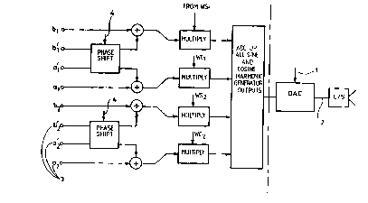
The invention may be applied to control the propeller
noise in an aircraft with two propellers. This example
is now described with reference to the accompanying
drawing, in which Figure l shows one type of output
wavefrom generator. Each output waveform generator
20 (for simplicity only one is shown) receives a -
tachometer pulse train, 1, from one of the propellers
and generates the anti-sound (second) signal, 2, for
each loudspeaker in synchronization with it (again
only one loudspeaker is shown for reasons of
25 simplicity). The phase and amplitude of the
loudspeaker signals are governed by output weighting
coefficients, 3, which are adjusted by the adaptive
algorithm.
The values of aj and bj, are the cosine and sine
output weighting coefficients of the anti-sound signal
for propeller 1, for each loudspeaker (at each
harmonic ;), and the values of a'j and b'j, are the
35 coefficients for propeller 2. These output weighting
.
-. : ... . . : ............ .. : : . , . . ~ ..
... . . . - -.
-: , . : - .
W092/08224 PCT/GB91/0185
~~ J ~ I ~J
coefficients are adjusted by the adaptive algorithm
once per adaptive update. Regularly the phase
signal, ~ , or a timing signal from which the phase is
derived, is re-measured and used to co..,bine the
values of aj, a'j, bj, and b~j according to the
equation:
c = a + atCp - b'Sp
d = b + b'Cp + a'Sp
.
(the subscript j has been dropped for clarity)
1~ where:
c is the combined coefficient for the cosine
generator,
d is the combined coefficient for the sine
generator,
Cp is the cosine of the phase angle (of
propeller 2 relative to propeller
1), and
Sp is the sine of the phase angle.
Each time a pulse is received from the tachometer
pulse train the output to each loudspeaker is
calculated according to the equation:
x(i) - cjWCj(i) + djWSj(i)
where WCj(i) is a stored cosine wave of harmonic
number j, and WSj(i) is a stored sine wave of harmonic
number j. This represents the sum of the cosine and
... . , ~ . , . . . . . . , . -
.. , . . . . - . :. :
. .
. ~
'. ' ' ~. . ~:: : ; . '- : . ,, . . ' ~ .. ,
: -, ~ ~ ; . : ,
- .
- , - . .
,: ' ~' '.... ' ; , . ' , ' ~ .
~092/08224 PCT/GB91/01850
J v IJ ~ J
sine generator outputs weighted by the coefficients
Cj and dj and summed for each harmonic j. In figure
l, two harmonics are being controlled.
; The adaption in the controller may be done with
reference to the third signals from microphones in the
cabin. These could be used to adjust the output
weighting coefficients a and b (or a' and b'), which
are subsequently used by the output waveform
generators to create the an'i-sound signals.
Other embodiments of the invention could use more than
two input signals and could have different forms of
output wave generators.
; . - . . . , , , . ... :: :, - , . .. . .. . .,: . . : .. ~ , ,