Note: Descriptions are shown in the official language in which they were submitted.
2U95~92
1 71727-108
BACKGROUND OF THE INVENTION
The invention relates to golf clubheads, and in
particular, to golf clubheads having varying hosel lengths in
order to achieve optimum clubhead size and weight distribution
within the main body of the clubhead.
BRIEF DESCRIPTION OF THE DRAWING
Reference is made to the accompanying drawing in which
is shown an illustrative embodiment of the invention from which
its novel features and advantages will be apparent.
In the drawing:
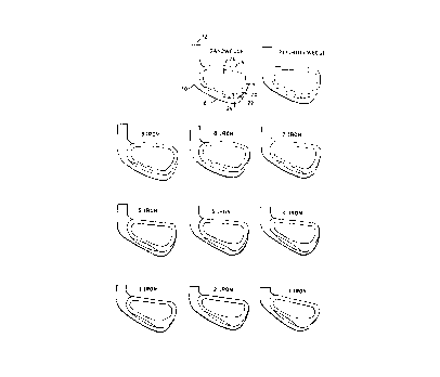
Figure 1 shows an iron golf clubhead;
Figure 2 shows a back view of a set of golf club irons
according to the invention;
Figure 3 shows a front view of a set of golf club irons
according to the invention;
Figure 4 shows a side view comparison of the varying
hosel lengths according to the invention;
Figure 5 shows a front view of golf club woods according
to the invention;
Figure 6 shows a blind bore section of a hosel; and
Figure 7 shows a golf club wood having an enlarged face.
The hosel portion of a golf club is the tubular shaped
member which connects the head portion of the club to the shaft
portion of the club. Hosels are generally all the same length,
i.e., they do not vary from club to club within a set.
Golf club irons are designed with varying degrees of
loft, ranging from a minimum of about 15~ for a number 1 iron to a
maximum of about 60~ for a wedge type club. Golf clubs also vary
2095092
la 71727-108
in length. Golf club woods are designed with varying degrees of
loft ranging from about 8~ to about 27~. The different degrees of
loft and length help to control the trajectory and distance a golf
ball is hit. With reference to Figure 1, a golf club lron
includes a blade member 2 having a toe portion 4, a top ridge 6, a
bottom sole portion 8 and a heel portion 10. Extending from the
heel portion region of the clubhead is a hosel portion 12 adapted
to receive and be retained on a shaft member (not shown). The
clubhead is provided with a substantially flat surface 16, having
therein a center of percussion 18, which is the spot ideally
adapted to engage a golf ball at impact, and a rear surface 20
having a perimeter 22 defining a cavity 24.
One of the problems associated with the less lofted
clubs is that the size of those clubs has generally been
restricted by the head weight. The less lofted iron
2095092
clubheads are typically the lightest weight because they
will be cut to the longest overall club length and must
still be within an acceptable swing weight range. These
restrictions have thus far dictated that the size of the
main body of the less lofted iron clubhead remain very small
volumetrically. It is desirable to increase the size of the
main body of the less lofted clubs in order to make them
easier to hit.
It is also desirable to provide more of an impact on
the actual distribution of weight within the normal golf
clubhead shape or profile. The optimum weight distribution
system of an iron type golf clubhead is one in which the
optimum amount of weight is positioned toward th'e toe area
of the head on the less lofted clubs and progressively
shifts toward the heel area of the head on the more lofted
clubs. Placement of the weight in these positions helps
eliminate the average golfer's natural tendency to hit the
ball to the right when using the less lofted clubs, and hit
the ball to the left when using the more lofted clubs.
Efforts to move or redistribute enough weight to produce a
significant impact in this area have not been completely
successful because there is simply not enough material or
mass contained within the main body of the conventional
clubhead profile which could be moved or redistributed to
effectively achieve the optimum results.
One attempt at improvement in this area has been the
use of hosels of varying lengths to permit redistribution of
weight within the main body of the clubhead. U.S. Patent
No. 4,715,601 to Lamanna discloses the use of hosels of
varying lengths to achieve a relatively constant center of
percussion for the set of lofted clubs. Lamanna discloses a
design for clubs in which the hosel portions of the clubs
progress in length as the loft increases, with the standard
or conventional length hosel on the lowest lofted club and
the longest, or longer than conventional length hosel on the
highest lofted club. As the clubhead weight increases from
CA 0209~092 1998-04-07
the lower lofted irons to the higher lofted irons, the weight
of the hosel portion also increases. Therefore, the center of
mass is maintained at a relatively constant location in relation
to the blade portion of the clubhead and the planar face of the
blade portion.
Thus, T~m~nna discloses that the location of center
of mass remains relatively constant for all of the various
lofted clubs. As mentioned above, it is desirable to have a
set of golf clubs in which the center of mass shifts, with the
optimum amount of weight toward the toe area on the less lofted
clubs shifting progressively toward the heel on the more lofted
club.
SUMMARY OF THE INVENTION
The invention provides a set of golf club irons, each
having a head portion, and a hosel connecting the head portion
to a shaft portion, with the head portions ranging in loft from
a minimum of approximately 14~ for a least lofted club to a
maximum of approximately 54~ for a highest lofted club wherein
the lengths of the hosels range from a length of less than 2"
for the least lofted clubs to approximately 2 5/8" for the
highest lofted clubs, and each head portion has a heel, a toe
and a sole, and weight is positioned toward the toe and the
sole on the least lofted club and progressively moves toward
the heel as the loft of the club increases, with more weight
positioned toward the heel of the highest lofted club, so that
a location of a center of percussion for the clubs is not
uniform for each club in the set.
71727-108
CA 0209~092 1998-04-07
The invention also provides a set of golf club woods,
each having a head portion and a hosel connecting the head
portion to a shaft portion, with the head portions ranging in
loft from a minimum of approximately 9.5~ for a least lofted
club to a maximum of approximately 23~ for a highest lofted
club, wherein the lengths of the hosels range from less than
approximately 2" for the least lofted club to approximately
3 1/8" for the highest lofted club, and each head portion has
a heel and toe, and weight is positioned toward the toe on the
least lofted club, and progressively moves toward the heel as
the loft of the club increases, with more weight positioned
toward the heel on the highest lofted club so that a location
of a center of percussion for the clubs is not uniform for each
club in the set.
The invention also provides a golf club comprising a
hosel connecting a head portion to a shaft portion, said hosel
having a blind bore defined by a circular opening in said hosel,
terminating in an angled bottom surface in said hosel, said
bottom surface adapted to receive an end of said shaft portion,
said shaft portion having an end cut at an angle matching the
angle of said angled bottom surface such that when the end of
the shaft portion is received in the blind bore section, said
bottom surface joins said end of said shaft portion so that no
lateral movement of the shaft occurs in the hosel.
The invention also provides a set of golf clubs, each
club having a hosel connecting a head portion to a shaft portion,
said hosel having a blind bore section defined by a circular
71727-108
CA 0209~092 1998-04-07
openingin said hosel, terminating in an angled bottom surface
in said hosel, said bottom surface adapted to receive an end of
said shaft portion, said shaft portion having an end cut at an
angle matching the angle of said angled bottom surface, such
that when the shaft is received in the blind bore section, said
bottom surface joins said end of said shaft portion, so that no
lateral movement of the shaft occurs in the hosel.
It is desired to provide a set of golf clubs in which
the size of the main body of the less lofted clubs is increased
to make them easier to hit, and to provide a set of golf clubs
having more of an impact on the actual distribution of weight
within the normal golf clubhead shape or profile. Preferably,
the optimum amount of weight is moved toward the toe area of
the head on the less lofted clubs with the weight shifting
progressively toward the heel area of the head on the more
lofted clubs. This locates the center of gravity of each
clubhead in an optimum position.
The present invention provides a golf club which may
help eliminate or reduce the average golfer's natural tendency
to hit the ball to the right when using the less lofted clubs
and hit the ball to the left when using the more lofted clubs.
By providing a set of golf clubs which utilizes
progressively longer hosel lengths for the purpose of enlarging
the main body of the clubhead and/or redistributing weight
within the main body of the clubhead, the overall size of the
number 1 iron can be increased to that of a number 3 iron, with
the size of the sand wedge remaining standard and all clubs in-
71727-108
CA 0209~092 1998-04-07
5a
between progressing in size in order to maintain continuity in
the set. The increase in size of the main body of the clubhead
makes the club easier to hit.
The extra weight may also be redistributed around the
perimeter of the cavity in order to shift the center of gravity
to the optimum position to maximize the distance and direction
when striking a golf ball. In the less lofted clubs, the
weight is redistributed toward the toe area and then moves back
progressively toward the heel in the more lofted clubs.
The above and other features of the invention,
including various novel details of construction and combination
of parts, will now be more particularly described with reference
to the accompanying drawings and pointed out in the claims. It
will be understood that the particular devices embodying the
invention are shown by way of illustration only and not as
limitations of the invention. The principles and features of
this invention may be employed in various and numerous embodi-
ments without departing from the scope of the invention.
DESCRIPTION OF THE PREFERRED EMBODIMENT
Referring to the drawings, and particularly Figures 1
and 2, it will be seen that the illustrative golf clubhead
includes a blade member 2 having a toe portion 4, a top ridge
portion 6, a bottom sole portion 8 and a heel portion 10.
Extending from the heel portion of the clubhead is a hosel
portion 12 adapted to receive and be retained on a shaft member
(not shown). The clubhead is provided with a substantially flat
surface 16, having therein a center of percussion 18, which is
71727-108
CA 02095092 1998-04-07
5b
the spot ideally adapted to engage a golf ball:at impact, and
a rear surface 20 having a perimeter 22 defining a cavity 24.
71727-108
209a~92
Figs. 2-4 show a set of clubs including irons numbers
1-9 and the pitching wedge and sand wedge. The hosel length
of the number 1 iron is reduced from the standard length of
2 5/8" to 1 3/8", and the length of each hosel progresses
1/8" per club to a conventional 2 5/8" length on the sand
wedge. Flg. 4 shows a side view comparison of the hosel
lengths for each iron. The hosel offsets progress from
0.276" on the number 1 iron to 0.076" on the sand wedge,
thereby giving the appearance of a straight or conventional
blade on the short irons.
The leading edge 30 of the clubhead is straight or
without toe to heel radius. The leading edge 30~ may be
radiused or rolled in the direction from the bottom of the
face to the sole. There is no lndentation where the leading
edge blends into the hosel from the number 8 iron through
the sand wedge.
In a first embodiment, the weight made available from
reducing the size of the hosel 12 is used to enlarge the
size of the clubhead. For example, the overall size of the
number 1 iron is increased to that of a conventional number
3 iron. The overall size of the sand wedge remains
conventional and all clubs in between progress in size in
order to maintain continuity in the set.
By reducing the-length of the number 1 iron hosel from
its normal length of 2 5/8" to approximately 1 3/8",
approximately 35 grams of weight are removed which may be
used to increase the size of the main body. As an example,
in a typical set of golf club irons, the head weight
specification increases 7 grams per club number, i.e. a
normal number 1 iron head weight specification is 232 grams,
the number 2 iron head weight is 239 grams, etc. By
reducing the hosel length on the number 1 iron and utilizing
a very thin (1/8") blind bore hosel configuration, as shown
in Fig. 6, approximately 35 grams of weight can be
2a~509~
7 71727-108
redistributed over the main body of the clubhead. That excess
weight makes it possible to produce a number 1 iron with a main
body size which is volumetrically similar to that of a
conventional number 3 iron. Once the main body of the iron is
increased to the size of a number 3 iron, the sand wedge remains
at a standard size and all club members in between are
progressional.
Fig. 6 shows a blind bore section of a hosel. The oval
44 represents the angle cast inside the bore. The dotted lines 46
represent the hosel bore and the area 42 between the oval 44 and
the sole 8 is the blind bore section.
As the hosel length increases by 1/8" per club number,
the blind bore section located at the base of the hosel will also
increase or get thicker by an additional 1/8" per club number, or
in other words, the hosel bore depth remains constant at 1 1/4"
throughout the set for the number 1 iron through the sand wedge
due to the progressively increasing blind bore section. In order
to accomplish this, the tips of the shafts used on the short hosel
clubs, i.e. the numbers 1 through 4 irons, are cut at exact
matching angles to fit properly. This procedure also creates a
mechanical locking device thus improving the aspect of clubhead to
shaft bonding. That is, it reduces the risk that the shaft will
separate from the clubhead if the bond, e.g. epoxy cement, should
fail and ensures that no lateral movement of the shaft in the
hosel will occur.
The invention is applicable to woods as well as irons
because the same features are desired on both, i.e. maximum
enlargement of the main body of the less lofted clubs. Figure 5
v
7~9509~
7a 71727-108
shows a front view of the varying hosel lengths for the driver and
numbers 1, 3, 5 and 7 woods.
The physical dimensions of the progressive length hosel
theory of the main body head enlargement are outlined below:
.~, .
209~ ~92
WOODS
Approx. Approx.
Overall Hosel
Club Hosel Bore Approximate Hosel Bore
No. Length Depth Configuration
1 1 5/8" 1 1/2" Blind bore with shaft stopping
1/8" from sole of club
3 2 1/8" 1 1/2" Blind bore with shaft stopping
5/8" from sole of club
2 5/8" 1 1/2" Blind bore with shaft stopping
1 1/8" from sole of club
7 3 1/8" 1 1/2" Blind bore with shaft stopping
1 5/8" from sole of club
IRONS
- Approx. Approx.
Overall Hosel
Club Hosel Bore Approximate Hosel Bore
No. Length De~th Confi~uration
1 1 3/8" 1 1/4" Blind bore with 1/8" solid
section between bottom of
hosel and sole of club
2 1 1/2" 1 1/4" Blind bore with 1/4" solid
section between bottom of
hosel and sole of club
3 1 5/8" 1 1/4" Blind bore with 3/8" solid
section between bottom of
hosel and sole of club
4 1 3/4" 1 1/4" Bllnd bore with 1/2" solid
section between bottom of
hosel and sole of club
1 7/8" 1 1/4" Blind bore with 5/8" solid
section between bottom of
hosel and sole of club
6 2" 1 1/4" Blind bore with 3/4" solid
section between bottom of
hosel and sole of club
7 2 1/8" 1 1/4" Blind bore with 7/8" solid
section between bottom of
hosel and sole of club
8 2 1/4" 1 1/4" Blind bore with 1" solid
section between bottom of
hosel and sole of club
2 3/8" 1 1/4" Blind bore with 1 1/8" solid
section between bottom of
hosel and sole of club
PW 2 1/2" 1 1/4" Blind bore with 1 1/4" solid
section between bottom of
hosel and sole of club
SW 2 5/8" 1 1/4" Blind bore with 1 3/8" solid
section between bottom of
hosel and sole of club
2Q950~2
In a second embodiment, the weight available from
reducing the hosel length on the less lofted clubs is used
to redistribute the weight withln the main body of the
clubhead. As mentioned above, by reducing the hosel length
to approximately 1 3/8" long and util zing a very thin 1/8"
blind bore type hosel configura~ion, approximately 35 grams
of weight can be removed from the heel section of the
clubhead which can then be redistributed to the toe area of
the head, thus greatly impacting the center of percussion or
weight distribution of the head. The 35 grams of mass is
moved to the toe area of the number 1 iron. The mass can be
gradually moved back toward the heel area of the clubhead by
increasing the length of the hosel by 1/8" per club until
the conventional 2 5/8" overall hosel length is achieved on
the sand wedge.
The weight which is removed from the hosel area may be
redistributed around the perimeter of the cavity. Weight
may be positioned low in the sole and toward the toe on the
less lofted irons and progress toward the heel on the more
lofted irons. This dramatically increases the toe/heel
weighting aspect within the main body of the clubhead.
As the hosel length increases by 1/8" per club number,
the blind bore section at the base of the hosel will also
increase or get thicker by an additional 1/8" per club
number, or in other-words, the hosel bore depth would
remain constant at 1 1/4" throughout the set from the number
1 iron through the sand wedge due to the progressively
increasing blind bore section. In order to accomplish this,
the tips of the shafts used on the short hosel clubs, i.e.
the number 1 iron through the number 4 iron, are cut to an
exact matching angle for proper fit. This procedure also
creates a mechanical locking device thus improving the
aspect of clubhead to shaft bonding.
CA 0209~092 1998-0~-06
This theory is also applicable to woods as well as
irons because the same distribution of weight features are
desired on both, i.e. the optimum amount of weight located
toward the toe on the less lofted clubs (i.e. the driver and
the number 1 iron) progressively moved toward the heel on the
more lofted clubs (number 7 wood and sand wedge).
As an alternative, a wood clubhead with a
conventionally sized main body can be improved by
redistributing weight from the hosel 12 to the face area 32.
By extending the face height, an enlarged hitting surface is
created utilizing a high lip 34 as high as the topline (crown)
of the face 38, as shown in Fig. 7. This face extension or
lip 34 is highest on the less lofted clubs (or driver)
progressively decreasing in size on the more lofted clubs (or
7 wood).
The physical dimensions of the progressive length
hosel theory of weight distribution are outlined below:
WOODS
Approx. Approx.
Overall Hosel
Club Hosel BoreApproximate Hosel Bore
No. Lenqth Depthconfiquration
5/8" 1 1/2" Blind bore with shaft stopping
1/8" from sole of club
3 2 1/8" 1 1/2"Blind bore with shaft stopping
5/8" from sole of club
2 5/8" 1 1/2"Blind bore with shaft stopping
1/8" from sole of club
7 3 1/8" 1 1/2"Blind bore with shaft stopping
5/8" from sole of club
IRONS
1 3/8" 1 1/4~Blind bore with 1/8" solid
section between bottom of
hosel and sole of club
2 1 1/2~ 1 1/4"Blind bore with 1/4" solid
section between bottom of
hosel and sole of club
3 1 5/8" 1 1/4"Blind bore with 3/8" solid
section between bottom of
71727-108
209S092
11
hosel and sole of club
4 1 3/4" 1 1/4" 31ind bore with 1/2" solid
sectlon between bottom of
hosel and sole of club
1 7/8" 1 1/4" Blind bore with 5/8" solid
section between bottom of
hosel and sole of club
6 2" 1 1/4" Bllnd bore with 3/4" solid
sectlon between bottom of
hosel and sole of club
7 2 1/8" 1 1/4'' 81ind bore with 7/8" solid
section betT~een bottom of
hosel and sole of club
8 2 1/4" 1 1~4" Bllnd bore with 1" solid
section be~ween bottom or
hosel and sole of club
9 2 3/8" 1 1/4" Bllnd bore with 1 1/8" solid
section between bottom of
hosel and sole of club
PW 2 1/2" 1 1/4" Bl'nd bore with 1 1/4" solid
section between bottom of
hosel and sole of club
SW 2 5/8" 1 1/4" Blind bore with 1 3/8" solid
section between bottom o~
nosel and sole of club
In a third embodiment, the weight made from reducing
the leng~h of the hosel is used both to increase the size of
the clubheads and to shift the weight toward the toe on the
less lofted clubs and toward the heel on the highest lofted
clubs. The physical dimensions of the clubheads embodying
those features are outlined below:
IRONS
Club Hosel Hosel 312de Toe Heel Finished
No. Loft Length Offse r Length .Ielght He~ght Head Wt.
(approx~ ~~approx) (approx) (approx) (approx) (ap~rox)
1 lg-1~ 1.315" 0.276" 2.875" 2.063" 1.000" 221 g
2 17-19~ 1.~00'' 0.256" 2.37i" 2.094" 1.031" 234 g
3 20-22~ l.625'' 0.236" 2.875" 2.125" i.063" 241 g
4 23-25~ 1.750" 0.216" 2.875" 2.156" 1.094'' 248 g
27-29~ 1.875" 0.196" 2.875" 2.188" 1.125" 255 g
~ 31-33~ 2.000" 0.175" 2.875" 2.219" 1.156" 262 ~
7 35-37~ 2.125'' 0.156'' 2.375~' 2.250" l.i88~ 269 g
8 39-41~ 2.250'' 0.136'' 2.875'' 2.2q1'' 1.219'' 270 g
9 43-45~ 2.375~ 0.116'' 2.a75" 2.313" 1.250" 283 g
?W 49-51~ 2.500~' 0.096" 2.315" 2.344" i.281" 290 g
SW ~4-56~ 2.625" 0.016" 2.875" 2.344" 1.313" 297 g
20~S092
Hosel Bore Depth = 1.25"
Hosel Bore I.D. = 0.355" (bottom) to 0.364" (exit point)
or tapered tip
Hosel O.D. - 0.540"
Sole Radius - 10"
Sole Width (center) = 0.675"/#1 to 0.875"/SW
Toe Radius - 3"
Top Toe Radius - 0.438"
Bottom Toe Radius - 0.750"
Heel Radius - 0.750"
Neck Radius - 0.250"
Top Line Thickness - 0.220" radiused
WOODS
Club No. Head Weiqht Lie Angle Loft
1 195 g 54~ 9.5~ or 10.5~
3 203 g 55~ 15~
210 g 56~ 20~
7 217 g 57~ 23~
It is to be noted that the dimensions for the r~m~i ni ng
woods follow in progression. For example, the head weight
of the number 2 wood is approximately 198-199 g; the head
weight of the number 4 weight is approximately 213.5g, etc.
It is to be understood that the present invention is by
no means limited to the particular construction herein
disclosed and/or shown in the drawings, but also comprises
any modifications or equivalents within the scope of the
disclosure.