Language selection

Search

Patent 2095501 Summary

Third-party information liability

Some of the information on this Web page has been provided by external sources. The Government of Canada is not responsible for the accuracy, reliability or currency of the information supplied by external sources. Users wishing to rely upon this information should consult directly with the source of the information. Content provided by external sources is not subject to official languages, privacy and accessibility requirements.

Claims and Abstract availability

Any discrepancies in the text and image of the Claims and Abstract are due to differing posting times. Text of the Claims and Abstract are posted:

  • At the time the application is open to public inspection;
  • At the time of issue of the patent (grant).
(12) Patent Application: (11) CA 2095501
(54) English Title: CALIBRATION CUVETTE
(54) French Title: CUVETTE DE CALIBRATION
Status: Deemed Abandoned and Beyond the Period of Reinstatement - Pending Response to Notice of Disregarded Communication
Bibliographic Data
(51) International Patent Classification (IPC):
  • G01N 01/00 (2006.01)
(72) Inventors :
  • AHMAD, JAMIL (United States of America)
  • RICCITELLI, SAMUEL D. (United States of America)
  • BANKERT, CHARLES S. (United States of America)
  • HANNAH, RICHARD (United States of America)
  • DAVIS, CHRISTOPHER L. (United States of America)
(73) Owners :
  • PURITAN-BENNETT CORPORATION
(71) Applicants :
  • PURITAN-BENNETT CORPORATION (United States of America)
(74) Agent: SMART & BIGGAR LP
(74) Associate agent:
(45) Issued:
(22) Filed Date: 1993-05-04
(41) Open to Public Inspection: 1993-11-23
Availability of licence: N/A
Dedicated to the Public: N/A
(25) Language of filing: English

Patent Cooperation Treaty (PCT): No

(30) Application Priority Data:
Application No. Country/Territory Date
07/888,549 (United States of America) 1992-05-22

Abstracts

English Abstract


Docket No. 33496
CALIBRATION CUVETTE
ABSTRACT OF THE DISCLOSURE
The calibration cuvette apparatus for storing and
calibrating a chemical sensor in a tonometered solution
includes an upper cuvette section and a lower cylindrical
valve section for alternately sealing the cuvette section
and admitting a gas mixture to the cuvette section. The
upper cuvette section has relatively narrow diameter
upper and lower ends on either side of a wide diameter
middle portion. The cuvette section is adapted to
receive the sensor and retain the sensor in a fluid bath
in the cuvette section so that the chemical sensor
portion is disposed approximately in the center of the
wide middle portion of the cuvette section. The chamber
formed within the cuvette section is thus shaped so as to
maintain the sensor in a position in the fluid bath so
that any gas bubbles within the chamber will not dry the
sensor. A lower end portion of the cuvette section
includes a gas communication inlet for introducing gas
into said chamber to equilibrate the tonometered buffer
solution.


Claims

Note: Claims are shown in the official language in which they were submitted.


Docket No. 33496
WHAT IS CLAIMED IS:
1. A calibration cuvette apparatus having a housing
adapted to contain a calibration fluid and to receive a
chemical sensor, said calibration cuvette apparatus
comprising:
a generally tubular cuvette section having a
longitudinal axis formed in said housing, said cuvette
section having a hollow chamber with upper, middle and
lower sections, said upper and lower portions having a
relatively smaller inner diameter than said middle
portion, said supper end portion having an opening for
receiving said sensor;
a valve section formed in said housing integrally with
said cuvette section for introducing gas into said
cuvette chamber, said valve section having first and
second longitudinal end portions, a gas communication
port extending between said cuvette chamber and an inner
valve chamber extending between said valve section end
portions; and
a valve plug slidable within said valve chamber
between a first sealing position and a second gas
communication position, said valve plug having first and
second longitudinal ends and an outer circumference
portion, and said valve plug having a gas communication
channel with an inlet port at one of said valve plug ends
and a gas outlet port at said outer circumference portion
adapted to be aligned to be in communication with the
cuvette gas communication port when said valve plug is in
said gas communication position.
2. The apparatus of Claim 1, wherein said cuvette
section is formed in the shape of an elongated dual
frustrum, with said cuvette section comprising an upper
frustoconical portion including said narrow upper end
portion and a wide diameter lower end portion contiguous
with said middle portion, and a lower frustoconical

11 Docket No. 33496
portion including a wide diameter upper end portion
contiguous with said middle portion and said narrow lower
end portion.
3. The apparatus of Claim 1, wherein said narrow
upper end portion of said cuvette section includes a
cylindrical neck portion adapted for receiving said
sensor.
4. The apparatus of Claim 1, wherein said wide
diameter middle portion of said cuvette section comprises
a generally cylindrical, tubular section.
5. The apparatus of Claim 1, wherein said narrow
upper end portion of said cuvette section includes a
catheter luer fitting for receiving said sensor.
6. The apparatus of Claim 1, wherein said valve
chamber portion is in communication with said cuvette gas
communication port.
7. The apparatus of Claim 1, wherein said valve
section and said valve plug include means for aligning
said valve plug within said valve chamber.
8. The apparatus of Claim 7, wherein said means for
aligning said valve plug within said valve chamber
comprises tongue and groove means including at least one
rib on one of said valve plug and said valve section and
at least one corresponding groove adapted to interfit
with said rib on the other of said valve plug and said
valve section.
9. The apparatus of Claim 1, wherein said valve plug
gas communication channel includes means for filtering
said gas mixture.

12 Docket No. 33496
10. The apparatus of Claim 1, wherein said chamber in
said cuvette section contains said fluid, and said means
for introducing gas into said chamber includes means for
dispersing said gas in said fluid.
11. The apparatus of Claim 9, wherein said means for
filtering said gas mixture comprises a biofilter.
12. The apparatus of Claim 10, wherein said means for
dispersing said gas in said fluid comprises a porous
frit.
13. A calibration apparatus adapted to contain a
calibration fluid and to receive a chemical sensor, said
calibration apparatus comprising:
an upper elongated, generally tubular dual
frustrum shaped cuvette section, said cuvette section
having a longitudinal axis, said cuvette section having
relatively small diameter upper and lower end portions
compared to the diameter of a middle portion of said
cuvette section, said upper, lower, and middle portions
of said cuvette section forming a hollow chamber within
said cuvette section, said upper portion having an
opening for receiving said sensor, and said lower portion
including a gas communication inlet for introducing gas
into said chamber;
a valve section for selectively introducing a gas
into said hollow chamber formed integrally with said
cuvette section, said valve section having first and
second longitudinal end portions, an axis extending
between said end portions, and an inner valve chamber;
and
a valve plug moveable within said valve chamber
between a first sealing position and a second gas
communication position, said valve plug having a gas
communication channel and a gas outlet port adapted to be
aligned to be in communication with the cuvette gas

13 Docket No. 33496
communication inlet when said valve plug is in said gas
communication position.
14. The apparatus of Claim 13, wherein said valve
plug includes sealing means for sealing said gas
communication inlet when said valve plug is in said
sealing position.
15. The apparatus of Claim 13, wherein said valve
plug gas communication channel includes means for
filtering said gas mixture.
16. The apparatus of Claim 15, wherein said means for
filtering said gas mixture comprises a biofilter.
17. The apparatus of Claim 13, wherein said valve
section and said valve plug include means for aligning
said valve plug within said valve chamber.
18. The apparatus of Claim 17, wherein said means for
aligning said valve plug within said valve chamber
comprises tongue and groove means including at least one
rib on one of said valve plug and said valve section and
at least one corresponding groove adapted to interfit
with said rib on the other of said valve plug and said
valve section.
19. The apparatus of Claim 13, further comprising
means for dispensing said gas into said gas communication
inlet.
20. A calibration cuvette apparatus having a housing
adapted to contain a calibration fluid and to receive a
chemical sensor to be immersed in said calibration fluid,
said calibration cuvette apparatus comprising:
a hollow cuvette section having a longitudinal axis
formed in said housing, said cuvette section having an

14 Docket No. 33496
inner chamber with an upper end portion, a middle
portion, and a lower end portion including means for
introducing gas into said chamber, said upper end portion
having means for disposing said sensor substantially
centrally within said middle portion, and said hollow
cuvette section having an inside diameter which is
relatively larger at said middle portion than at said
upper and lower end portions such that gas bubbles in
said middle portion will not dry said sensor.
21. The calibration cuvette of Claim 20 wherein said
means for introducing gas into said chamber comprises:
a valve section formed in said housing integrally with
said cuvette section, said valve section having an inner
valve chamber with first and second longitudinal open end
portions, and a gas communication port permitting fluid
communication between said cuvette chamber and said inner
valve chamber; and
a valve plug slidable within said valve chamber
between a first sealing position and a second gas
communication position, said valve plug having first and
second longitudinal ends and an outer circumference
portion, and said valve plug having a gas communication
channel with an inlet port at one of said valve plug ends
and a gas outlet port at said outer circumference portion
adapted to be aligned to be in communication with the
cuvette gas communication port when said valve plug is in
said gas communication position.
22. The apparatus of Claim 20, wherein said cuvette
section is formed in the shape of an elongated dual
frustrum, with said cuvette section comprising an upper
frustoconical portion including said narrow upper end
portion and a wide diameter lower end portion contiguous
with said middle portion, and a lower frustoconical
portion including a wide diameter upper end portion
contiguous with said middle portion and said narrow lower

Docket No. 33496
end portion.
23. The apparatus of Claim 20, wherein said upper end
portion of said cuvette section includes a cylindrical
neck portion adapted for receiving said sensor.
24. The apparatus of Claim 20, wherein said wide
diameter middle portion of said cuvette section comprises
a generally cylindrical, tubular section.
25. The apparatus of Claim 20, wherein said upper end
portion of said cuvette section includes a catheter luer
fitting for receiving said sensor.
26. The apparatus of Claim 21, wherein said valve
chamber is in communication with said cuvette gas
communication port.
27. The apparatus of Claim 21, wherein said valve
section and said valve plug include means for aligning
said valve plug within said valve chamber.
28. The apparatus of Claim 27, wherein said means for
aligning said valve plug within said valve chamber
comprises tongue and groove means including at least one
rib on one of said valve plug and said valve section and
at least one corresponding groove adapted to interfit
with said rib on the other of said valve plug and said
valve section.
29. The apparatus of Claim 21, wherein said valve
plug gas communication channel includes means for
filtering said gas mixture.
30. The apparatus of Claim 20, wherein said chamber
in said cuvette section contains said fluid, and said
means for introducing gas into said chamber includes

16 Docket No. 33496
means for dispersing said gas in said fluid.
31. The apparatus of Claim 29, wherein said means for
filtering said gas mixture comprises a biofilter.
32. The apparatus of Claim 30, wherein said means for
dispersing gas into said chamber comprises a porous frit
member for sparging gas into said fluid.
33. A calibration apparatus adapted to contain a
calibration fluid and to receive a chemical sensor, said
calibration apparatus comprising:
an upper elongated, generally tubular dual frustrum
shaped cuvette section, said cuvette section having a
longitudinal axis and a hollow inner chamber with an
upper end portion, a lower end portion, and a middle
portion, said hollow inner chamber having an inner
diameter which is relatively smaller in said upper and
lower end portions than in said middle portion, said
upper end portion having an opening for receiving said
sensor, and said lower end portion including a gas
communication inlet for introducing gas into said hollow
inner chamber; and
valve means connected to said lower end portion
operative to selectively introduce a gas through said gas
communication inlet into said hollow inner chamber.
34. The calibration apparatus of Claim 33, wherein
said valve means further comprises:
a valve housing section connected to said cuvette
section, said valve housing section including an inner
valve chamber and a port connecting said valve chamber
with the gas communication inlet of said cuvette; and
valve plug means moveable within said valve chamber
for selectively connecting an external fluid or gas
source to said chamber in fluid communication with said
gas communication inlet.

17 Docket No. 33496
35. The calibration apparatus of Claim 33, wherein
said valve means further comprises:
a valve housing section connected with said cuvette
section, said valve section having first and second
longitudinal end portions, an axis extending between said
end portions, and an inner valve chamber; and
a valve plug moveable within said valve chamber
between a first sealing position and a second gas
communication position, said valve plug having a gas
communication channel and a gas outlet port adapted to be
aligned to be in communication with the cuvette gas
communication inlet when said valve plug is in said gas
communication position.
36. The apparatus of Claim 35, wherein said valve
plug includes sealing means for sealing said gas
communication inlet when said valve plug is in said
sealing position.
37. The apparatus of Claim 35, wherein said valve
plug gas communication channel includes means for
filtering said gas mixture.
38. The apparatus of Claim 37, wherein said means for
filtering said gas mixture comprises a biofilter.
39. The apparatus of Claim 35, wherein said valve
section and said valve plug include means for aligning
said valve plug within said valve chamber.
40. The apparatus of Claim 39, wherein said means for
aligning said valve plug within said valve chamber
comprises tongue and groove means including at least one
rib on one of said valve plug and said valve section and
at least one corresponding groove adapted to interfit
with said rib on the other of said valve plug and said

18 Docket No. 33496
valve section.
41. The apparatus of Claim 34, further comprising
means for dispensing said gas into said gas communication
inlet.

Description

Note: Descriptions are shown in the official language in which they were submitted.


209~01
Docket No. 33496
CALIBRATION CWETTE
BACKGROUND OF THE INVENTION
Related Applications:
This application is a continuation in part of
copending Serial No. 07/565,463, filed August 10, l99O.
Field of the Invention:
This invention generally relates to calibration
of analytical chemistry devices, and more particularly
relates to a device for calibrating sensors for measuring
gas concentrations and pH of a fluid.
Description of Related Art:
In modern medicine, measurement of acidity (pH), and
oxygen and carbon dioxide levels in the blood has become
an important factor in the determination of the
respiratory status of a patient. Although electrodes
have been developed which are capable of measuring these
blood factors in fluids, such electrodes are of limited
use in measurement of in vivo blood pH levels. optical
sensors called "optodes" have been developed for taking
intravascular mealqurements of acidity and other blood
analytes such as oxyge~ and carbon dioxide. Such optical
sensors typically include a fluorescent indicator dye
placed over the tip of an optical fiber and covered by a
membrane which is permeable to the chemical of interest.
It is frequently desireable to keep such sensors wet
prior to use in an aqueous, tonometered buffer solution
which is isotonically adjusted to match the ionic
strength of the fluid of interest, such as blood. Such
sensors must also be sterilized, such as in an autoclave,
. .
, ~'' ' - ' . ;. :
- ,
.

209a~1
Docket No. 33496
before they are used intravenously. The autoclaving
process can cause pressure buildup in the buffer
solutions, placing unusual stresses on the fluid
container in which the sensor is sterilized to cause
leakage of the container. It is also desirable to
calibrate such sensors before use, and frequently several
times daily, using tonometered sample liquids with known
levels of the analyte of interest. One method of
preparing an appropriate tonometered buffer solution
involves bubbling a prepared gas mixture, such as of CO2,
2' and N2 through the solution until equilibration of the
gas mixture in the solution occurs. However, it has been
found that drying of the membrane of the chemical sensor
can occur where gas bubbles come in contact with the
chemical sensor, affecting the performance of the sensor.
It is also useful to provide a bio-filter in the gas
bubbling apparatus to filter the gas mixture before it
enters the solution, but it has been found that such
filters can become clogged if exposed to the buffer
solution for extended storage periods.
Accordingly, there remains a need for an apparatus
that will allow storage of the sensor in an appropriate
fluid to protect the sensor from drying out, that will
provide a way of isolating the bio-filter from becoming
clogged during a period of storage of the sensor in the
fluid, and that will provide for good sealing of the
sensor and fluid in the apparatus for the internal
pressure which builds up in the fluid during the
autoclaving process.
30SUMMARY OF THE INVENTION
Briefly and in general terms, a calibration cuvette
apparatus according to the present invention comprises an
apparatus for storing and calibrating a chemical sensor
in a tonometered buffer solution. The apparatus includes
.-. ,, ~, ::
- ~- .
~ ,,: ,. . .. :
:
, ~ :

209~01
3 Docket No. 33496
an upper cuvette section and a lower cylindrical valve
section for sealing the cuvette section in one valve
position, while allowing the admission of a gas mixture
t~ the cuvette section in the other valve position. The
upper cuvette section has relatively narrow diameter
upper and lower ends on either side of a wide diameter
middle portion. The cuvette section is adapted to hol~
the chemical sensor in a fluid bath in the cuvette
section so that the chemical sensor is disposed
approximately in the center of the wide middle portion of
the cuvette section. The chamber formed within the
cuvette section is thus shaped so as to maintain the
sensor in a position in the fluid bath so that any gas
bubbles within the chamber will not dry the sensor. A
lower end portion of the cuvette section includes a gas
communication inlet for introducing gas into the chamber
to equilibrate the tonometered buffer solution.
The lower, generally tubular valve section is
preferably formed integrally with the cuvette section
with an axis extending perpendicular to the longitudinal
axis of the cuvette section. A generally cylindrical
elastomeric valve plug is disposed within the valve
chamber, and is slidable between a first sealing position
and a second gas communication position. The valve plug
includes a gas communication channel with an inlet port
at one of the ends of the valve plug and a gas outlet
port at the outer circumference of the valve plug adapted
to be aligned to be in communication with the cuvette gas
communication inlet when the valve plug i5 in the gas
communication position. The cuvette section i~
preferably formed in the shape of an elongated dual
frustrum, with the cuvette section having an upper
frustoconical portion and a lower frustoconical portion,
with the wide diameter portion of the cuvette section
located at the wide diameter portions of the two
frustoconical portions. The gas communication channel
,

2093~01
4 Docket No. 33496
also preferably includes a filter and a sparger for
filtering the gas and dispersing the gas bubbles evenly
within the cuvette section as it is introduced into the
chamber of the cuvette.
Other aspects and advantages of the invention will
become apparent from the following detailed description,
taken in conjunction with the accompanying drawings,
which illustrate, by way of example, the principles of
the invention.
10BRIEF DESCRIPTION OF THE DRAWINGS
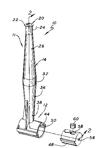
FIGURE 1 is a perspective view of the calibration
cuvette apparatus of the invention; and
Fig. 2 is a cross-sectional view taken along line 2-2
of Fig. 1.
15DETAILED DESCRIPTION OF THE PREFERRED EM~ODIMENT
As is shown in the drawings which are provided for
purposes of illustration, and not by way of limitation,
the invention is embodied in a calibration cuvette
apparatus for storing and calibrating a chemical sensor
in a tonometered solution. The apparatus has a unique
shape which allows for storage and calibration of the
sensor in an appropriate solution, protecting the sensor
from extended contact with bubbles in the solution which
could otherwise dry a portion of the sensor sufficiently
to affect the performance of the sensor. The apparatus
also provides a bio-filter for gas to be infused in the
tonometered solution. The apparatus also includes a
valve section for isolating the bio-filter from becoming
clogged during a period of storage of the sensor in the
solution and sealing the sensor and solution in the
cuvette section of the apparatus during autoclaving of
the apparatus.
, , -: . ,.. .,, .:.
,, - ~ .

209S501
Docket No. 33496
Referring to Figure 1, the present invention is
embodied in a calibration cuvette apparatus 10 having a
novel shaped cuvette section 11 adapted to receive a
catheter having a chemical sensor portion. The general
shape of the cuvette section is that of a dual frustrum
designed to prevent the chemical sensor from contacting
any bubbles that may form within a tonometexed buffer
solution in the cuvette section, to keep the chemical
sensor of the catheter wet, in any position of the
calibration cuvette apparatus, when the chemical sensor
is inserted into the approximate middle of the cuvette
section. The calibration cuvette apparatus also includes
a lower generally cylindrical valve section 12 formed
integrally with the housing 14 of the upper cuvette
section. The housing of the calibration cuvette
apparatus is preferably comprised of glass, in order to
allow the retention of various gas mixtures, particularly
in order to facilitate long term intravenous blood gas
catheter storage in the calibration cuvette apparatus.
Alternatively, it may be possible to form the housing of
the calibration cuvette from a variety of plastics which
may be suitable for retaining different gas mixtures.
As further illustrated in Figure 2, the upper dual
frustrum cuvette section is generally elongated and
tubular in its side aspect, having a vertical,
longitudinal axis 16. An aperture 18 is provided at the
extreme upper luer end 20 for receiving the chemical
sensor catheter. The upper end also preferably includes
an upper cylindrical neck portion 24 connecting the mouth
22 of the luer end with the narrow upper end 28 of the
upper frustoconical portion ~6 of the cuvette section.
The upper frustoconical portion gradually enlarges
downwardly to form a relatively wider lower end 30 of the
upper frustoconical portion contiguous with the wide
diameter middle portion 32. The middle portion 32 is
preferably formed in the shape of a short cylindrical
''.

209~01
6 Docket No. 33496
tube, and extends downwardly to be contiguous with the
~ide diameter upper section 36 of the lower frustoconical
portion 34 of the cuvette section. The diameter of the
Lower frustoconical portion gradually decreases
downwardly to the narrow diameter and lower end 38 of the
Lower frustoconical portion.
The upper cuvette section thus forms a hollow, inner
chamber 40 for receiving the chemical sensor catheter,
such as an intravascular blood gas sensor, and
maintaining the position of the chemical sensor in the
approximate center of the widened middle portion of the
upper cuvette section, in a bath of buffer solution. The
narrow diameter lower end of the frustoconical portion of
the cuvette section includes a lower aperture 42, which
serves as a gas communication inlet for introducing gas
mixtures formulated as desired into the buffer solution
to maintain a desired proportion of dissolved gases in
the solution for purposes of storage and calibration of
the chemical sensor.
The lower cylindrical valve section includes a lower
valve chamber 44 formed in the housing 46 of the
cylindrical valve section, which is preferably formed
integrally with the housing of the upper cuvette section.
The valve section is generally cylindrical, having a
horizontal longitudinal axis extending perpendicular to
the vertical, longitudinal axis of the upper cuvette
section. A generally cylindrical elastomeric, piston-
type plug 48 is preferably disposed coaxially within the
lower valve chamber, and is slidable within the valve
chamber between the sealing position which is illustrated
in Fig. 2, and a gas communication position. Although
the plug is preferably formed of an elastomer, such as
rubber or polyurethane, to form a seal at the cuvette
section opening, the plug may be formed of other
materials such as plastic or metal, with appropriate
. :.
.., . . ~ ,,
.,: . ~., ., . :
, ~

2asss~l
7 Docket No. 33496
seals. In order to facilitate alignment of the
elastomeric plug with the lower, gas communication
aperture in the upper cuvette section in each of these
two valve positions, the inner surface of the cylindrical
valve housing includes one or more, and preferably two,
alignment channels or grooves 50 adapted to receive
corresponding ribs or ridges 52 on the elastomeric plug,
extending in a longitudinal direction aligned with the
axes of the valve chamber and elastomeric plug.
Alternatively such grooves could be placed on the plug,
and ridges on the inner wall of the valve chamber.
The elastomeric plug preferably also includes a gas
communication channel 56 for receiving the specially
formulated gas mixture to be introduced into the upper
cuvette section. The gas co~munication channel includes
a gas communication inlet 54 at one of the longitudinal
ends of the elastomeric plug for receiving gas from an
external supply, and an outlet end on the circumference
of the elastomeric plug, which preferably includes a
filter chamber 58. A biofilter 60 is preferably disposed
in the filter chamber for filtering out undesirable
particulate matter which may be carried along from an
exterior gas supply line. A frit 62, such as a porous
polymeric frit or a porous glass frit, is also preferably
disposed in the lower end 38 of the lower frustoconical
portion of the cuvette section adjacent to the lower
aperture 42 for sparging gas flowing through the lower
gas communication aperture 42 into the upper cuvette
section, when the gas communication channel of the
elastomeric plug is placed in its gas communication
position aligned with the gas communication aperture of
the cuvette section. Other materials which may be
adapted for use in frit 62 include ceramics, other fine
porous materials, or the like. Closely adjacent to the
filter chamber on the circumference of the elastomeric
plug is a sealing area 64 on the circumference of the
' ':
.

2095~01
8 Docket No. 33496
elastomeric plug, adapted to be aligned with the opening
in the cuvette section to seal the cuvette section in the
valve sealing position during autoclaving and storage.
Support structures, such as the fins 66a and 66b, may
also be formed along with the housing to connect the
upper housing of the cuvette section with the lower
housing of the valve section, to provide added support
and strength to the narrow diameter connection of the
cuvette section to the cylindrical valve section.
It will be apparent to those skilled in the art from
the foregoing that the calibration cuvette apparatus will
maintain a seal around the sealing area of the
elastomeric plug against the internal pressure of the
cuvette solution caused by the elevated temperatures
which occur during autoclaving, and that the biofilter
will be isolated and protected during autoclaving and
storage when the elastomeric plug of the valve is
disposed in its sealing position. It is also significant
that the elastomeric plug of the valve section can slide
to a gas communication position to align the biofilter
with the opening in the cuvette section to the solution
and the sparger frit through which a gas mixture can be
bubbled when the chemical sensor in the cuvette section
is to be calibrated. DUP to the novel dual frustrum
shape of the cuvette section, gas bubbles in the solution
in the cuvette section will either dissolve in the
solution, rise to the upper end of the cuvette section
when the cuvette section is disposed vertically, or rise
to the wide diameter middle section of the cuvette
section if the cuvette section is placed horizontally.
Thus, a chemical sensor 68 placed in the approximate
middle of the cuvette section will be protected from any
gas bubbles in the solution within the cuvette section,
and drying of the chemical sensor, either during
calibration or storage will be prevented. It is also
significant that the biofilter in the elastomeric plug
~ .

209~01
9 Docket No. 33496
can be kept isolated from the solution in the upper
cuvette section during a storage period and before
calibration of a chemical sensor, so that particulate
matter within the solution will not clog the sparger or
biofilter.
While particular forms of invention have been
illustrated and described, it will be apparent that
various modifications can be made without departing from
the spirit and scope of this invention. Accordingly, it
is not intended that the invention be limited, except as
by the appended claims.
'`` ' : ~ :. ,
.
: . - , :
,~ . .
,
, .:

Representative Drawing
A single figure which represents the drawing illustrating the invention.
Administrative Status

2024-08-01:As part of the Next Generation Patents (NGP) transition, the Canadian Patents Database (CPD) now contains a more detailed Event History, which replicates the Event Log of our new back-office solution.

Please note that "Inactive:" events refers to events no longer in use in our new back-office solution.

For a clearer understanding of the status of the application/patent presented on this page, the site Disclaimer , as well as the definitions for Patent , Event History , Maintenance Fee  and Payment History  should be consulted.

Event History

Description Date
Time Limit for Reversal Expired 1997-05-05
Application Not Reinstated by Deadline 1997-05-05
Deemed Abandoned - Failure to Respond to Maintenance Fee Notice 1996-05-06
Inactive: Adhoc Request Documented 1996-05-06
Application Published (Open to Public Inspection) 1993-11-23

Abandonment History

Abandonment Date Reason Reinstatement Date
1996-05-06
Owners on Record

Note: Records showing the ownership history in alphabetical order.

Current Owners on Record
PURITAN-BENNETT CORPORATION
Past Owners on Record
CHARLES S. BANKERT
CHRISTOPHER L. DAVIS
JAMIL AHMAD
RICHARD HANNAH
SAMUEL D. RICCITELLI
Past Owners that do not appear in the "Owners on Record" listing will appear in other documentation within the application.
Documents

To view selected files, please enter reCAPTCHA code :


To view images, click a link in the Document Description column. To download the documents, select one or more checkboxes in the first column and then click the "Download Selected in PDF format (Zip Archive)" or the "Download Selected as Single PDF" button.

List of published and non-published patent-specific documents on the CPD .

If you have any difficulty accessing content, you can call the Client Service Centre at 1-866-997-1936 or send them an e-mail at CIPO Client Service Centre.


Document
Description 
Date
(yyyy-mm-dd) 
Number of pages   Size of Image (KB) 
Claims 1993-11-22 9 319
Abstract 1993-11-22 1 28
Drawings 1993-11-22 1 25
Descriptions 1993-11-22 9 362
Representative drawing 1999-08-04 1 13
Fees 1995-03-29 1 72