Note: Descriptions are shown in the official language in which they were submitted.
2~9~3'74
-
. A HEATER, A METHOD OF NANUFACTURING THE SAME, AND
AN ANTI-CONDENSATION MIRROR INCORPORATING THE SAME
FIELD OF THE lNv~NlloN
The present invention relates to a heater which is
produced from a material having a PTC (Positive
Temperature Coefficient) of resistance, for example,
semiconductor ceramics of a barium titanate system and
used as a uniform-tE ~clature heater or local heater in
various fieIds, and to a method of manufacturing the
heater. The present invention also relates to an
anti-condensation mirror for use in a high humidity
envi~ t such as a bathroom, having the heater for
pL~venting cnn~n~tion from forming on the mirror
surface.
BACRGROUND OF THE lNV~N~l~lON
-- 2 --
~ ~ 9~
A heater incorporating a plate-like heating element
made of a PTC thermistor is conventionally known. The PTC
thermistor is a heating element having a positive
temperature coefficient of resistance and, for example, is
produced from a PTC material such as semiconductor
ceramics of a barium titanate system. The PTC thermistor
has low resistance at temperatures ranging from room
temperature to Curie temperature Tc (resistance transition
temperature) and a rapid increase in the resistance when
the temperature exceeds the Curie temperature Tc. With
this characteristic, when a voltage is applied to the
heating element, the heating element draws high currents
initially as the resistance is low at low temperatures,
resulting in a rapid increase in the temperature. On the
other hand, the t~ cLature of the heating element does
not exceed a predetr ine~ temperature because the
resistance increases rapidly when the temperature exceeds
the Curie t~ )_Lature Tc. Thus, the heating element
constantly maintains the predet- ined temperature.
Namely, the heating element including the PTC thermistor
has self-controlling temperature characteristics.
Accordingly, there is no need for a heater with such a
heating element to have circuits for controlling the
heated t _- ature to be a predetermined temperature and
for preventing overheating. Additionally, such a heater
2~
-- 3 --
is very safety.
A heater of this type is disclosed in Japanese
Publication for ~A~; ned Utility Model Application No.
26226/1972. The structure of the heater is as follows.
Electrodes are formed on the upper and lower surfaces of a
plate-like heating element made of a PTC thermistor. A
te inAl board is mounted on the outer surface of each
electrode, a heat transfer board is mounted on the outer
surface of one of the t~ inAl boards, and an electrical
insulating board is mounted on the outer surface of the
other t~ ;nAl board. Japanese Publication for Une~ ned
Utility Model Application No. 53498/1983 also discloses a
heater of this type. The heater of this document is
constructed such that electrodes are formed on the upper
and lower surfaces of a plate-like heating element made of
a PTC thermistor, an electrode board or a tr inAl board
is mounted on the outer ~urface of each electrode, and an
electrical insulating board is mounted on the outer
surface of each t~ in~l board. In these heaters, lead
wires as feeders are co~nected to the t~ ;nAl boards by,
for example, a solder. Electrical power is supplied to
the heating element by connecting the lead wires to a
power supply.
However, these structures fail to provide sufficient
insulation, and therefore the safety of the heaters drops,
8'74
-- 4 --
particularly, in a high humidity envilo -nt.
Japanese Publication for ~ ned Utility Model
Application No. 9283/1991 discloses a heater which solves
such problems. In this heater, electrodes are formed on
the upper and lower surfaces of a plate-like heating
element made of a PTC thermistor, and lead wires are
soldered to the outer surfaces of the electrodes. And,
the heating element, the electrodes and the connections of
the lead wires and the electrodes are coated with a
heat-conductive electrical-insulating resin, such as a
silicone resin.
With this structure, satisfactory insulation is
achieved. However, since the lead wires are soldered to
the outer faces of the electrodes, the heat conductive
insulating resin coat is nee~ed to have a thickness which
covers up bumps on the electrode surfaces caused by the
soldering of the lead wires, resulting in an increase in
the thickness of the resin layer. Consequently, the
heater with this structure becomes rather thicker and
larger, but is not capable of efficiently conducting heat
from the heating element to an object to be heated.
In addition, when the heater incorporating a PTC
thermistor as a heating element is used, if the heating
element is not coated well or the insulation structure is
not appropriate, the electrical characteristics may
2~9~1~'7~
-- 5
deteriorate, causing electrical insulation defect and
variations in the electric resistance. Such deterioration
is caused by dust and humid in the atmosphere. In
particular, when dew is formed on the electrode surface of
the heating element, that moisture causes an electrical
chemical reaction on the electrode surface upon the
application of a voltage. This may cause the electric
resistance to vary considerably. In order to solve such a
problem, Japanese Publication for F - ;ned Patent
Application No. 47500/1978 and ~ - ined Utility Model
Application No. 9283/1991 disclose heating elements
covered with an electrical insulating cover member such as
a resin material.
For instance, with a covering method disclosed in the
above Japanese ~ - ine~ Patent Application No. 47500/1978,
a heating unit formed by connecting lead wires to a
heating element is covered with an electrical insulating
cover member. In this case, in order to position the
heating unit more easily and properly in the electrical
insulating cover member formed by molding, the covering is
performed through the following processes.
Firstly, a plastic pot having an open top and a base
with holes for the corresponding lead wires of the heating
unit is prepared. Secondly, the heating unit is placed in
the pot while pulling out the lead wires through the
q~r4
holes. Next, the lead wires are fastened to the holes
with a sealer so that the heating element is positioned at
the center of the pot and that the holes are completely
sealed. Then, an epoxy series resin material is injected
into the pot and hardened.
However, this conventional method requires minute
work including pulling out the lead wired through the
holes of the pot, positioning the heating element at the
center of the pot using tweezers and fixing the lead wires
to the holes with a sealer. In other words, complicated
work is required to cover the heating unit with the
electrical insulating covering material. Meanwhile,
Japanese Publication for r ined Utility Model
Application No. 9283/1991 does not disclose any method for
solving the above-mentioned problems.
In a room with high humidity such as a bathroom, an
anti-condensation mir~ror capable of preventing
condensation from forming on- the mirror by heating is
conventionally used.
Japanese Publication for Un~ ;ne~ Utility Model
Application No. 155371/1985 discloses an anti-con~PnC~tion
mirror of this type. As described in the document, in the
anti-condensation mirror, a plate-like heating element is
attached to the rear surface of a mirror and the front
surface of the mirror is heated by conducting electricity
7~
-- 7
to the heating element. For example, the plate-like
heating element is a film-like heating element formed by
applying a thermal coating cont~ining carbon and metal to
a heat-resistant polymer film.
In the case of another anti-con~en~ation mirror, a
sheathed heater is attached to the rear surface of the
mirror, and the front surface of the mirror is heated by
conducting electricity to the sheathed heater. For
example, the sheathed heater is a heating cable element
formed by covering metallic wires with a heat-resistant
polymer.
With these structure, however, in order to maintain
the temperature of the heating element at a predete ine~
temperature and to ensure safety, it is necessary to
provide a t~ _lature control circuit and a circuit for
eventing overheat. Consequently, the size of the
anti-condensation mirr~or ~ec~ -5 larger. Additionally,
when the film-like heating element is attached to the rear
surface of the mirror, if a layer of air is produced
between the film-like heating element and the mirror and
if electricity is conducted to the heating element under
this condition, there is a possibility of producing heat
and causing fire. The reason for this is that the layer
of air separates film-like heating element from the mirror
at an area, and therefore the heat produced at the area
;~9~374
-- 8 --
can not escape, resulting in localized overheating. In
the case of an anti-condensation mirror using the heating
cable element, it is difficult to fasten the heating
element closely to the rear surface of the mirror,
resulting in low conductivity of the heat from the heating
element to the mirror.
In order to overcome such difficulties, various types
of anti-conde~Ation mirrors incorporating a heater having
a heating element made of the PTC th~rri~tor as a heat
source are suggested. With this structure, since the PTC
thermistor has the self-controlling temperature
characteristics, it is possible to omit the temperature
control circuit and the circuit for preventing
overheating, enabling a reduction in the size of the
anti-con~en~Ation mirror. Moreover, there is no
possibility that localized overheat causes a fire.
Japanese PublicatiQn for Un~r ined Utility Model
Application No. 108154/1989 discloses sùch a
conventional-type anti-condencation mirror. This
anti-conden~Ation mirror is constructed by attaching a
heater cable having a positive temperature coefficient of
resistance to the periphery of the mirror and forming on
the rear surface of the mirror a heat-transfer layer in
contact with the heater. U.S. Pat. No. 4,933,533 also
discloses a conventional-type anti-cond~n~tion mirror.
~5~4
g
This anti-con~n~ation mirror is constructed by mounting a
heating cable element on the rear surface of the mirror.
The heating cable element is formed by covering a resin
cont~ining a carbon having a positive temperature
coefficient of resistance with a polyvinyl chloride.
Furthermore, Japanese Publication for Un~ ned
Utility Model Application No. 65497/1973 also discloses
such an anti-condensation mirror. This anti-condensation
mirror is constructed as follows. An electrical
conduc~ive board, an electrical insulating substrate, an
electrical conductive board and a the -1 insulating board
are mounted in this order on the rear surface of the
mirror with or without a heat transfer board thereon. A
PTC ~h,~ tor is inserted into each of a plurality
through holes formed in the insulating substrate. The
electrodes on both surfaces of the PTC thermistor are
connected to both th~e conductive boards, so that
electricity is conducted to the PTC the i.stor through the
conductive boards.
With this structure, in order to efficiently conduct
the heat produced by the PTC the i ~tor to the mirror, it
is necessary to provide a heat transfer board betwéén the
mirror and the PTC th~ i ~tor.
However, with the structure disclosed in the above
Japanese Un~ - ined Utility Model Application No.
7~
-- 10 --
108154/1989, since the cable heater is attached to the
periphery of the mirror, the anti-condensation effects are
produced from the periphery. Consequently, if an
anti-condensation mirror incorporates a large-sized
mirror, it takes a longer time for a central area that
usually requires anti-condensation effects to receive the
effects.
With the structure disclosed in U.S. Pat. No.
4,933,533, the heating cable elements are pressed against
the mirror by a plastic supporting member in order to
bring the heating cable elements into contact directly
with the rear surface of the mirror. However, as is
disclosed in the same document, it is extremely difficult
to attach the heating cable element of a considerably long
length of 13.5 m to the mirror by evenly pressing it
against the mirror. Moreover, since a space is formed
between the mirror and~ the sup~Ling h~r~ it is
difficult to efficiently and evenly conduct the heat from
by the heating cable element to the mirror.
On the other hand, with the structure disclosed in
the above Japanese Un~ - ined Utility Model Application
No. 65497/1973, it is possible to solve the problems that
Japanese Utility Model Application No. 108154/1989 and
U.S. Pat. No. 4,933,533 have. More specifically, with
this structure, since the PTC thermistor is mounted
- ......
-- 1 1 --
through the heat transfer and electrical conductive boards
on a desired area of the rear surface of the mirror, it is
possible to produce anti-condensation effects on the
desired area of the mirror with a shorter time. However,
since the heat transfer board, electrical conductive
board, electrical insulating substrate, electrical
conductive board and thermal insulating board are mounted
on the rear surface of the mirror, the anti-condensation
mirror has an increased thickness. This also causes
increases in the size and weight of the anti-con~n~ation
mirror. In addition, since this anti-condensation mirror
does not have an a~LopLiate insulation structure,
currents may leak.
Finally, each of the heating elements disclosed in
the above-mentioned documents are designed without much
considering the water vapor-proof properties of the
anti-co~den~tion mirrors when installed in a bathroom for
example. With their structures, it is difficult to wate~
and vapor-proof them. Therefore, when installing these
anti-condensation mirrors in the bathroom, a voltage of
commercial power supply can not be directly applied to the
heating elements due to safety reasons. Namely, it is
necessary to provide a transformer to lower the value of
voltage of the power supply, for example, to a value not
greater than 24 V, or to ask a specialized builder to
.
Z~;8 ~'4
.
install these anti-condensation mirrors. Thus, these
structures result in increased costs and complicated
h~n~l;ng of the anti-condensation mirrors.
,
SUMMARY OF THE lNv~hllON
An object of the present invention is to provide a
heater with a reduced thickness capable of efficiently
conducting the heat produced by a heating element to an
object to be heated.
In order to achieve the above object, a heater of the
present invention at least includes:
(1) a heating element made of a the istor having a
positive temperature coefficient of resistance;
(2) electrodes formed on upper and lower surfaces of
the heating element;
(3) a pair of flat metallic t~ in~s electrically
connected to the electro~des;
(4) a pair of feeders electrically connected to the
inner surfaces of the metallic te in~l s that face each
other; and
(5) an electrical insulating cover member for
covering exposed portions of the heating elemé~t, the
electrodes and of the metallic te_ inA 1s, and the
connections between the metallic t~ in~ls and the feeders
so as to insulate them from outside.
~ ~51~7 ~
With this structure, since the pair of feeders for
feeding electricity to the heating element are connected
to the inner surfaces of the metallic t~ ; nal s, no bumps
are produced in the outer surfaces of the metallic
te_ ; n~ 1 S even when the feeders are soldered to the
metallic te ;n~ls. Accordingly, there is no need to
increase the thickness of the insulating cover member at
the outer surfaces of the metallic t~ ; n~ 1~ to cover up
such bumps. As a result, it is possible to reduce the
thickness of the heater, and to i -ove the efficiency of
the heat transfer from the heating element to a .heated
object when the heater is mounted on the heated object.
Namely, the heater of the present invention is capable of
efficiently heating the heated object.
Another object of the present invention is to provide
a simplified manufacturing method of the heater by
simplifying the process~of covering a heating unit with
the electrical insulating cover ~~r.
In order to achieve the above object, a method of
manufacturing the heater of the present invention at least
includes the steps of:
(1) forming a heating unit by connecting a flat
metallic te i n~ 1 to each of electrodes formed on upper
and lower surfaces of a flat heating element made of a
thermistor having a positive temperature coefficient of
2~ 374
- 14 -
resistance and by connecting feeders to the metallic
t~ in~ls;
(2) disposing the heating unit at a predetermined
position on a substrate of an electrical insulating
material; and
(3) sealing exposed portions of the heating unit in
the electrical insulating cover by injection-molding the
insulating material after disposing the substrate in a
mold.
With this method, the heating unit of the heater is
covered with the insulating cover member by locating the
heating unit at a predetP- ine~ position on the substrate,
sealing exposed portions of the heating unit in the
insulating cover by injection-molding the insulating
material after disposing the substrate in the mold.
Therefore, there is no need to perform minute work
including locating the heating unit in the proper position
on the substrate, pulling the lead wires from the
substrate and securing the lead wires, thereby allowing
the heater to be more easily manufactured.
Still another object of the present invention is to
provide an anti-condensation mirror with reduced thickness
and weight and good insulation structure, which allows an
im~l~v~ - t of a heat transfer from a heating element to a
mirror, easy h~n~l i ng during installation, and a reduction
, - 15 -
in costs including the cost for the installation.
In order to achieve the above object, an
anti-condensation mirror of the present invention at least
includes:
(1) a mirror;
(2) a heat transfer plate closely fastened to the
rear surface of the mirror; and
(3) a plurality of heaters covered with an electrical
insulating cover member and mounted on the rear surface of
the heat transfer plate, each of the heaters incorporating
a flat heating element made of a thermistor having a
positive temperature coefficient of resistance.
With this structure, since the heater incorporating
the heating element i5 . covered with the electrical
insulating cover material, it has good vapor-proof
quality. The mi,rror is heated by a plurality of the
heaters mounted on the rear surface of the heat transfer
plate which is closely mounted on the rear surface of the
mirror. Thus, the- anti-condensation mirror is well
insulated. In addition, since the heater uses the heating
element made of a PTC t~P istor as a heat source and has
self-controlling temperature characteristics, there is no
need to incorporate circuits for controlling the heat of a
uniform temperature and for pI~vel~ting overheating. This
makes it possible to apply a voltage of the commercial
- 16 -
power supply directly to the heater without reducing the
value of the voltage. Consequently, the anti-condensation
mirror is more easily handled, for example, during
installation, and the costs including the cost for the
installation are decreased.
Moreover, the anti-condensation mirror is constructed
by a plurality of the heaters incorporating the heating
element, mounted on the rear surface of the heat transfer
plate which is fastened to the rear surface of the mirror.
Such a simplified structure allows a reduction in the
thickness and weight of the anti-cond~n~ation mirror, and
an i ov~ - t of the heat transfer from the heating
element to the mirror.
In order to achieve the above object, alternative
anti-condensation mirror of the present invention at least
includes:
(1) a mirror; .~
(2) a heat transfer plate closely attached to the
rear surface of the mirror;
(3) a plurality of heaters covered with an electrical
insulating material and mounted on the rear surface of the
heat transfer plate, each of the heaters incorporating a
flat heating element made of a PTC ~he i~tor; and
(4) a junction ~-r mounted on the rear surface of
the heat transfer plate, the junction member having
174
- 17 -
therein a connection area where the feeders of the heaters
and a power code are connected, the junction member
covering the connections between the feeders and the power
code.
Like the aboYé-mentioned anti-condensation mirror,
this anti-conden~tion mirror achieves the above object by
means of (1), (2) and (3).
With this structure, since the power code and the
feeders of the heaters mounted on the rear surface of the
heat transfer plate are connected with the junction member
covering the connections of the power code and the
feeders, the power code and the feeders are more easily
connected compared to the case where the junction - h~r
is not used. Moreover, this structure enables not only a
reduction in the length of the feeder, but also the
lengths of the feeders from the center of the junction
member to the heater to ~be substantially uniform, thereby
facilitating the manufacture of the heater. Furthermore,
the connections between the feeders and the power code are
easily waterproofed, if neq~e~, by applying waterproof
treatment to the junction member. Additionally, this
structure ~.events the feeders from getting loosénéd and
caught în other members.
In order to achieve the above object, still
alternative anti-condensation mirror of the present
3'7~
- 18 -
invention at least includes:
(l) a mirror;
(2) a heat transfer plate mounted on the rear surface
of the mirror;
(3) a plurality of heaters covered with an electrical
insulating cover member and mounted on the rear surface of
the heat transfer plate, each of the heaters incorporating
a flat heating element made of a PTC t~e i~tor; and
(4) a fixture for closely fastening the mirror to the
rear surface of the heat transfer plate, the fixture
having a base member attached to the rear surface of the
mirror and a fastening member of a resilient material, the
fastening ~r pressing the heat transfer plate against
the mirror by engaging with the base - ~r.
Like the above-mentioned anti-condensation mirrors,
this anti-condensation mirror achieves the above object by
means of (l), (2) and ~3).
With this structure, the heat transfer plate is
fastened to the rear surface of the mirror by the fixture,
i.e., the base 'CL mounted on the rear surface of the
mirror and the fastening member of resilient material
which engages with the base member. Therefore, '"i'f the
mirror and the heat transfer plate ~p~nd, they slide
suitably relative to each other. This arrangement
pl~vents the mirror from warping due to a difference in
2~9~7~
-- 19 --
linear expansion coefficient between the mirror and the
heat transfer plate. Moreover, the heat transfer plate is
fastened by engaging the base member with the fastening
member after placing the heat transfer plate on a
predetermined position of the rear surface of the mirror.
Thus, the heat transfer plate is located on the
predete ine~ position of the mirror without making the
heat transfer plate slide over the mirror, preventing the
mirror from being scratched. Furthermore, since the heat
transfer plate is fastened to the rear surface of the
mirror by engaging the fastening member of resilient
material with the base ~Pr, the heat transfer plate is
easily mounted on the mirror. For instance, in comparison
to the mounting of the heat transfer plate to the mirror
with an adhesive agent, the heat transfer plate is easily
1 v~d from the mirror when, for example, replacing the
heater.
For a fuller understAn~; ng of the nature and
advantages of the invention, reference should be made to
the ensuing detailed description taken in conjunction with
the accompanying drawings.
BRIEF DESCRIPTION OF THE DRAWINGS
Fig. 1 is a rear view of an anti-con~PnQAtion mirror
of the present invention.
2 ~ 917 L~
Fig. 2 is a sectional view of essential components
illustrating an assembly structure of a heater in the
anti-condensation mirror shown in Fig. 1.
Fig. 3 is a partially exploded schematic front view
of the heater.
Fig. 4 is a sectional view of the heater.
Figs. 5(a) is a perspective view illustrating the
manufacturing process of the heater, particularly, the
step of forming electrodes on a heating element, Fig. 5(b)
is a perspective view illustrating the step of connecting
lead wires to metallic tr in~l S and the step of mounting
the metallic t~ inAls on the electrodes, and Fig. 5(c) is
a perspective view illustrating a heating unit obtained
after the step of Fig. 5(b).
Fig. 6 is a vertical section illustrating the step of
injection ~l~ing the cover section of an insulating case
in the manufacturing prQcess of the heater, wherein the
heating unit is mounted on the base section of the
insulating case.
Fig. 7 is a schematic vertical section illustrating a
type of installation of the anti-conden~ation mirror on
the wall surface.
Fig. 8 is a vertical section of essential components
illustrating alternative assembly structure of the heater
shown in Fig. 2.
37~
Fig. 9 is rear view illustrating alternative
anti-condensation mirror of the present invention.
Fig. 10 is a front view of the heater shown in Pig.
9.
Fig. 11 is a vertical section of the heater.
Fig. 12(a) is a front view of the base section of the
insulating case shown in Fig. 11, Fig. 12(b) is a rear
view thereof, and Fig. 12(c) is a bottom view thereof.
Fig. 13 is a vertical section of essential components
illustrating an assembly structure of the heater.
Fig. 14(a) is a side view of the lid of the upper
junction member shown in Fig. 9, Fig. 14(b) is a front
view thereof, Fig. 14(c) is a vertical section cut across
line A-A of Fig. 14(b), and Fig. 14(d) is a bottom view
thereof.
Fig. 15(a) is a rear view of the main body of the
upper junction ~_L shown in Fig. 9, Fig. 15(b) is a
side view thereof, Fig. 15(c) is a front view thereof,
Fig. 15(d) is a vertical section cut across line B-B of
Fig. 15(c), and Fig. 15(e) is a bottom view thereof.
Fig. 16 is a front view illustrating the connections
between the lead wires of the heaters and power code and
the main body of the upper junction member.
Fig. 17 is a perspective view illustrating a
connecting t~ in~l shown in Fig. 16.
~9~874
- 22 -
.
Fig. 18 is a front view of the main body of the
middle junction member shown in Fig. 9.
Fig. 19 is a front view of the main body of the lower
junction member shown in Fig. 9.
- Fig. 20 is an enlarged view of the holder section
shown in Fig. 19.
Fig. 21 is a perspective view of a disassembled
- fixture shown in Fig. 9.
Fig. 22 is an explanatory view illustrating an
installation of a mirror on a heat transfer plate with the
fixture.
Fig. 23 is a perspective view illustrating a fixture
to be used instead of the fixture shown in Fig. 21.
- Fig. 24 is a rear view of alternative
anti-condensation mirror of the present invention.
Fig. 25(a) is a front view of the lid of the upper
junction - ~r shown,i~n Fig. 24, Fig. 25(b) is a side
view thereof, Fig. 25(c) is a vertical section cut across
line C-C of Fig. 25(a)
Fig. 26(a) is a rear view of the main body of the
upper junction, - ~r shown in Fig. 24, Fig. 26(b) is a
side view thereof, Fig. 26(c) is a front view théreof,
Fig. 26(d) is a vertical section cut across line D-D of
Fig. 26(c), and Fig. 26(e) is a bottom view thereof.
Fig. 27 is a front view illustrating the connections
;~9~
- 23 -
between the lead wires of the heaters and power code and
the main body of the upper junction member.
Fig. 28ta) is a perspective view of the inner
connecting t~ in~l shown in Fig. 27 and Fig. 28(b) is a
perspective view of the outer connecting te i nal shown in
Fig. 27.
Fig. 29 is a front view of the main body of the
middle junction member shown in Fig. 24.
Fig. 30(a) is a side view of the lid of the lower
junction member shown in Fig. 24 and Fig. 30(b) is a front
view thereof.
Fig. 31(a) is a rear view of the main body of the
lower junction member shown in Fig. 24, Fig. 31(b) is a
side view thereof, Fig. 31(c) is a front view thereof, and
Fig. 31(d) is a bottom view thereof.
Fig. 32(a) is a vertical section of an alternative
example of the heating-unit mounted on the base section of
the insulating case shown i~ Fig. 6, and Fig. 32(b) is a
perspective view of a cap used when assembling the heating
unit.
DESCRIPTION OF THE PREFERRED EMBODIMENTS
[EMBODIMENT 1]
The following description disçusses one preferred
embodiment of the present invention with reference to
2~ 74
- 24 ~
Figs. 1 through 8.
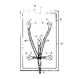
As illustrated in Fig. 1, an anti-condensation mirror
17 of this embodiment is formed by fixing a heat transfer
plate 2 to a rear surface of a rectangular mirror 1 with,
for example, an adhesive agent. A plurality of heaters 3
are mounted at predetermined intervals on a rear surface
2c of the heat transfer plate 2. Each of the heaters 3
includes a heating element 4 shown in Figs. 3 and 4.
The heat transfer plate 2 is made of a metal plate
with a high the -1 conductivity, such as an aluminum
plate, and is rectangular in shape and smaller than the
mirror 1. The heat transfer plate 2 is provided with five
holes 2a, shown in Fig. 2, for the installation of the
heaters 3. One of the installation holes 2a is formed at
the center of the heat transfer plate 2 and the other are
formed at four diagonal locations separated by a
~ predetr i net1 distance ~rom the center.
The heaters 3 are fixed to the heat transfer plate 2
by inserting flat-head screws 6 into the installation
- holes 2a and screwing nuts 7 on the screws 6. The
configuration of the installation holes 2a are determined
so that a head 6a of the flat-head screw 6 fits into the
installation hole 2a. More specifically, the installation
hole 2a has a cylindrical hollow section extPn~; ng a
predete ine~ distance from the rear surface 2c and a
74
_ 25 -
flaring section whose diameter increases gradually toward
the front surface 2b. Thus, the front surface 2b of the
heat transfer plate 2 to be attached to the rear surface
of the mirror 1 is flat. The configuration and ~; ~nsions
of the installation holes 2a are not strictly restricted
if they match the configuration and dimensions of the
flat-head screws 6.
As illustrated in Figs. 3 and 4, each of the heaters
3 includes a heating element 4, metallic t~ ;nAls 8, lead
wires 9 as feeders, and an insulating case 10 as an
electrical insulating cover member.
The heating element 4 has a positive temperature
coefficient of resistance and is formed by a PTC
~h~ ; stor that is pro~uce~ from semiconductor ceramics of
a barium titanate system c ,-'sing barium titanate doped
with a small amount of oxides of rare earth elements such
as La and Y, and oxides~of Nb and Bi. The PTC thermistor
has low resistance at t~ ,cLdtures from room temperature
to Curie tl ,- ature Tc (resistance transition
temperature), and the resistance abruptly increases above
the Curie t ,- ature Tc. With this characteristic, when
a voltage is applied to the heating element 4, the héating
element 4 draws high currents initially as the resistance
is low at low temperatures, resulting in an increased
consumption of electricity and a rapid temperature rise.
2~3S~74
- 26 -
Then, when the temperature of the heating element 4exceeds the Curie temperature Tc, the resistance increases
rapidly, thereby declining the consumption of electricity
significantly. Thus, the temperature of the heating
element 4 rises only up to a certain temperature and is
stably kept at that level. Namely, the heating element 4
has self-controlling t~ _Lature characteristics. The
Curie temperature Tc is set to an arbitrary temperature
between about 30 and 270 ~C by changing the composition of
material forming the heating element 4. For example, if a
part of the barium in barium titanate is replaced with Pb,
the Curie t- _~clature Tc shifts from the normal Curie
point of around 120 ~C to a higher temperature. On the
other hand, if a part of the barium is replaced with Sr,
the Curie t~ p_~ature Tc shifts to a lower temperature.
With this heating element 4, the Curie temperature Tc is
dete ;ne~ by considering the working condition, safety
and saving of electricity of the heaters 3. With this
arrangement, surface t~ clatures which are effective to
ent condensation from forming on the mirror 1 are
obtained.
As illustrated in Fig. 5(a), the heating elément 4
has a rather flat cylindrical ~hape. Electrodes 4a are
formed on the top and bottom surfaces of the heating
element 4 by applying thereto a silver coating for
example. A locating hole 4b is formed at the center of
the heating element 4 so that it passes through the top
and bottom surfaces.
As illustrated in Figs. 5(b) and S(c), each of the
metallic t~rrin~ls 8 is formed in the shape of a flat
plate with a diameter substantially equal to the diameter
of the heating element 4, and has at the center a locating
hole 8b whose diameter is substantially equal to the
diameter of the locating hole 4b of the heating element 4.
The metallic t~ in~l 8 is provided with a feeding point
8a to which the lead wire 9 is connected. The feeding
points 8a are parallel but out of alignment with each
other, and extend in a direction in which the lead wires 9
are inserted.
The metallic te in~l 8 and the heating element 4 are
electrically connected by bonding the electrode 4a and the
metallic te in~l 8 -together with, for example, an
epoxy/silver mixed conductive adhesive agent such as
DEMETRON 6290-0343 manufactured by Degussa AG. The lead
wires 9 are soldered to inner surfaces of the fee~ing
points 8a that face each other. In this case, due to the
positional relation between the feeding points 8a, one of
the lead wires 9 is connected to one of the metallic
te inAls 8 at a first position located on one side of a
plane perpendicular to the electrodes 4a and the other
- 2~5~
_ 28 -
lead wire 9 is connected to the other metallic t~ ; n~ 1 8
at a second position located on the other side of the
plane. This structure prevents the lead wires 9 from
causing an increase in the thickness of the heating
element 4. As illustrated in Fig. 4, the lead wires 9 are
pulled from the electrical insulating case 10 so that they
are parallel to a surface of the insulating case 10 to be
mounted on the heated object and a distance between the
mounting surface and each of the lead wires 9 becomes
equal. The heating element 4, the metallic t~ i n~1 S 8
and the lead wires 9 form a heating unit 14 as shown in
Fig. 5(c).
For example, the insulating case 10 is formed by an
electrical insulating the ~plastic such as 6-nylon, and
includes a base section 11 and a cover section 12 as a
cover ~r as shown in Fig. 4. The insulating case 10
covers and seals the heating unit 14, and has a fixing
hole 3a at the center which is used when fixing the heater
3 with a screw to the heated ob~ect. The insulating case
10 coveLs the ends of the lead wires 9 connected to the
metallic t~ i n~ 1 S 8 so as to p ~v~nL disconnection-of the
lead wires 9 when a dynamic load is applied to the
soldered connections of the lead wires 9 and the feeding
points 8a.
For example, the base section 11 and the cover
~:~3~87~
_ 29 -
section 12 of the insulating case 10 are formed as a
single piece through the following process. Firstly, the
heating unit 14 is placed in the injection-molded base
section 11. Then, after placing the base section 11 with
the heating unit 14 thereon in a mold, plastics as an
electrical insulating material is injection-molded to give
the cover section 12. With this process, the entire
heating unit 14 except the open ends of the lead wires 9
~ is fixed and sealed in the insulating case 10.
The base section 11 has a raised portion lla formed
at a portion correspon~ing to the periphery of the.-fixing
~~ hole 3a. When the.heating unit 14 is placed on the base
section 11, the raised portion lla fits into the locating
: hole 4b of the heating element 4 and-the locating holes 8b
of the metallic t~ in~ls 8, so that the heating unit 14
is held in pLopel position. Namely, the heating unit 14
c is positioned in an area.of the base section 11 around the
raised portion lla.
The requirements to be satisfied by the insulating
case 10 are a low shrinkage rate against heat, high
~h~ l conductivity, high -ch~nical strength, resistance
to the heated temperature of the heating elémént 4,
waterproof quality impervious to moisture including water
and vapor, airtight quality ; pelvious to air, and well
adhesiveness to the covering material of the lead wires 9.
- 30 -
For instance, the insulating case 10 produced from a
polymer alloy of nylon, polypropylene and glass fiber
meets these requirements. It is also possible to use
thermosetting plastics to form the insulating case lO.
A single insulating case 10 is constituted by the
base section 11 and the cover section 12. It is desirable
to form the base section 11 and the cover section 12 from
the same or similar electrical insulating materials in
order to achieve good affinity and an equal thermal
expansion coefficient. However, considering ~h~ ~1
conductivity, the base section 11 having high thermal
conductivity to the heated object and the cover member 12
radiating less heat into the air are more desirable. If
the thermal conductivity is taken into consideration prior
to the affinity and equal the -l expansion coefficient, a
material having good the_ -1 conductivity and electrical
insulation, for example~,~the polymer alloy is used for the
base section 11 and a material having relatively low
the -l conductivity, for example, an epoxy resin is used
for the cover section 12.
As illustrated in Fig. 1, the lead wires 9 connected
to the heaters 3 are connected to a power code 13. For
example, the lead wires 9 are connected to an external
power supply through the power code 13.
With reference to this structure, the method of
2~9~7
-- 31 --
manufacturing the heaters 3 is e:~plained below.
Firstly, the rather flat cylindrical heating element
4 shown in Fig. 5(a) is formed and sintered. Secondly, a
silver coating is applied to the top and bottom surfaces
of the heating element 4 and sintered to form the
electrodes 4a.
Next, as shown in Fig. 5(b), the metallic te inAls 8
are attached to the electrodes 4a with a conductive
adhesive agent, and the lead wires 9 are soldered to the
inner surfaces of the feeding points 8a of the metallic
te ;n~ls 8. Or, the metallic terrinAls 8 are attached to
the electrodes 4a with the conductive adhesive agent after
soldering the lead wires 9 to the fee~ing points 8a.
Consequently, the heating unit 14 shown in Fig. 5(c) is
obtA;ne~.
Then, as illustrated in Fig. 6, the heating unit 14
is placed on the injection-molded base section 11 of the
insulating case 10. At this time, the heating unit 14 is
positioned so that the raised portion lla of the base
section 11 fits into the locating hole 4b of the heating
element 4 and the locating holes 8b of the metallic
te ;nAls 8.
Subsequently, the base section 11 is placed in a
mold, and plastics is injection-molded to produce the
cover section 12. Thus, the base section 11 and the cover
~9~1~7'~
- 32 - .
section 12 of the insulating case 10 are formed as a
single piece. With this arrangement, since the entire
heating unit 14 except for the open ends of the lead wires
9 is thoroughly covered with and sealed in the insulating
case lO, the heating unit 14 is insulated from outside.
As a result, the heaters 3 shown in Figs. 3 and 4 are
obtained. For example, it is possible to attach a plug to
the ends of the lead wires 9 in order to more easily
connect the lead wires 9 to the external power supply.
Also, a female thread groove is formed in the fixing hole
3a, if nep~ed.
In this embodiment, the metallic terminals 8 are
, .
attached to the electrodes 4a of the heating element 4
with the electrical conductive adhesive agent. Although
attaching the metallic t~- in~l s 8 to the electrodes 4a
with the conductive adhesive agent is easily performed, it
limits the mass-production efficiency. The reasons for
this is that it takes about one day to harden the
conductive adhesive agent, and care is required to prevent
the conductive adhesive agent from flowing over the side
faces of the heating element 4 and causing the electrodes
4a having a short circuit.
In order to further i ~_~ve the efficiency of
mass-production of the heater 3, it is desirable to put a
cap 19 over the electrodes 4a and the metallic t~ i n~ 1 s 8
~9~
- 33 -
as shown in Fig. 32(a) instead of using the conductive
adhesive agent. The cap 19 is formed by the electrical
insulating material used for forming the insulating case
10. As illustrated in Fig. 32(b), a locating hole l9a is
formed at the center of the upper surface of the cap 19
and a window l9b for allowing the feeding points 8 to
protrude from the cap 19 is formed in a side face thereof.
The ~ ter of the locating hole l9a is substantially
equal to the major diameter of the raised portion lla.
The width of the window l9b corresponds to the horizontal
distance between the feeding points 8a, and the height of
the window l9b substantially corresponds to the total
amount of the thickness of the heating unit 4 and the
thickness of one metallic t~ in~l 8.
One example of design dimensions of the heater 3 is
given below. The thicknesses of the base plate of the
base section 11, the ,metallic t~ inAl 8, the heating
element 4, top plate of the cap 19 and the top plate of
the cover section 12 are 1.0 mm, 0.2 mm, 2.5 mm, 0.5 mm
and 0.5mm, respectively. Namely, the heater 3 has a
thickness of 4.9 mm. In the case where the metallic
tr i n~ 1 s 8 are attached to the electrodes 4a with the
conductive adhesive agent without using the cap 19, the
thickness of the top plate of the cover section 12 is set
to 1.0 mm. The ma~or dlameter of the heating element 4 is
- 34 _
.~ ,
set to 15 mm for example.
The manufacture of the heater 3 with the cap 19 is
discussed below. Firstly, the lower metallic te ina] 8,
the heating element 4 with electrodes 4a, and the upper
metallic t~ inal 8 are inserted in this order into the
base section 11 of the insulating case 10. Secondly, in
the step of soldering, the lead wires 9 are soldered to
the inner surfaces of the feeding points 8a that face each
other. However, it is not necessary to perform soldering
after the insertion of the electrodes 4a and the metallic
t~ inAls 8 into the base section 11, it may be performed
before or upon the insertion of each metallic t~ ;n~l 8a
into the base section 11. Then, the cap 19 is placed over
the metallic plate 8 while locating the locating hole l9a
and the window l9b of the cap 19 on the correspon~ing
positions of the raised portion lla and the feeding points
8a so as to complete the heating unit 14. Subsequently,
in~ection-molding is performed in the above-mentioned
manner.
By assembling the heating unit 14 with the cap 19
instead of the conductive adhesive agent, the time taken
for hardening the conductive adhesive agent is savéd and
the possibility that the flowing of the conductive
adhesive agent causes the electrodes 4a to have a short
circuit is eli in~ted. Thus, if the caps 19 are prepared,
~95~
- 35 -
the efficiency of mass production of the heater 3
uves .
The following description discusses a method ofmanufacturing the anti-condensation mirror 17 having the
heaters 3.
In manufacturing the anti-co~n~ation mirror 17, the
heaters 3 are first mounted on the heat transfer plate 2.
At this time, as illustrated in Fig. 2, the flat-head
screw 6 is inserted into the installation hole 2a from the
front surface 2b of the heat transfer plate 2. And, the
heater 3 is positioned so that the thread section 6b of
the flat-head screw 6 protruding through the installation
hole 2a from the rear surface 2c fits into the fixing hole
3a of the heater 3.
Then, the nut 7 is fastened on the flat-head screw 6
so as to stick a surface of the heater 3 closely to the
rear surface 2c of the heat transfer plate 2. Since the
~ i r ~ Ler of the head 6a of the flat-head screw 6
is equal to the -~i diameter of the flaring section of
the installation hole 2a, the head 6a can never protrude
from the front surface 2b of the heat transfer plate 2.
When fastening the flat-head screw 6 with the nut 7, a
washer or spring washer is placed between the heater 3 and
the nut 7, if necessary.
The manufacture of the anti-con~n~ation mirror 17 is
~ ~9 ~7~
complete by sticking the heat transfer plate 2 having the
heaters 3 to a predet~rmine~ location of the rear surface
of the mirror 1.
In the heaters 3 of this embodiment, as described
above, since the lead wires 9 are connected to the inner
surfaces of the feeding points 8a of the metallic
te inAls 8, the connections of the lead wires 9 do not
produce any bumps on the outer surfaces of the metallic
t~ inAl5 8. Accordingly, there is no need to increase
the thickness of the insulating case 10 at the outer
surfaces of the metallic t~ inAls 8 to cover up the
bumps. Namely, it is possible to form the thin insulating
case 10. IIo,eov~l, this structure enables not only a
reduction in the thickness of the heaters 3, but also,
when the heaters 3 are mounted on a heated object such as
the heat transfer plate 2, the heat from the heating
element 4 to be efficiently conducted to the heated
object.
Fur~h~ -re, the fixing hole 3a formed at the center
of the heater 3 enables the heater 3 to be screwed to the
heated object by fitting a screw into the fixing hole 3a.
This makes it possible to stick the upper or lower surface
of the heater 3 closely to the heated object, thereby
allowing the heat from the heating element 4 to be
efficiently conducted to the heated object.
~ ~39~
Also, since the metallic terr;n~l 8 is formed in the
shape of a flat plate, the insulating case 10 of a reduced
thickness and an i ,lov~d thermal conductivity is
achieved.
Additionally, since the heating unit 14 including the
heating element 4 is covered with the insulating case 10
and electrically insulated from the heated object, it is
possible to attach the heaters 3 closely to the heated
object of metal for example. And, since the insulating
case 10 is waterproof, the heaters 3 may be used to heat
and warm liquid such as water and milk. If the insulating
case 10 is formed by a silicon resin, the heaters 3 are
also fl r ~loof .
In this embo~i - t, each heater 3 includes one
heating element 4. However, the number of the heating
element 4 is not restricted to one, and it is possible to
use more than one heating element 4. The configuration of
the heaters 3 is not restricted to cylindrical shape, and
the heaters 3 can be formed in various shapes, for
example, into a polygonal plate. Also, the configuration
of the heating element 4 is not restricted to a rather
flat cylindrical shape, and it may be formed in the shape
of a disk or a rectangular parallelopiped shape. The
number and the position of the heating element 4 and of
the fixing hole 3a in the heater 3 are not restricted to
7~
- 38 -
those described in the embodiment, and they are changeable
according to the size of the heater 3 and the type of
assembly of the heaters 3 and the heated object.
With the above method of manufacturing the heaters 3,
the covering of the heating unit 14 with the insulating
case 10 is carried out as follows. Firstly, the heating
unit 14 is positioned such that the raised portion lla of
the base section 11 of the insulating case 10 fits into
the locating hole 4b of the heating element 4 and the
locating holes 8b of the metallic tf ; nA 1s 8. Then,
after placing the base section 11 in a mold, the cover
section 12 is injection-molded. Thus, the heating unit 14
is sealed in the insulating case 10. Unlike a
conventional method, this method does not require
complicated work including positioning the heating unit 14
in the base section 11, pulling the lead wLres 9 from the
heating unit 14 and fi~i ng the lead wires 9, thereby
facilitating the manufacture of the heaters 3. Besides,
since the raised portion lla of the heating unit 14 fits
into the above-mentioned holes when the heating unit 14 is
positioned on the base section 11, the heating element 4
is easily placed in proper position in the insulating case
10 to be injection-molded.
Moreover, since the heater 3 includes the heating
element 4 as heating means formed by the PTC thermistor,
37'~
- 39 -
when the temperature promptly rises to a predet~ i ned
temperature after conducting electricity, the heater 3
automatically keeps the temperature. Thus, in the
anti-condensation mirror 17 having the heaters 3, the
surface temperature of the mirror 1 quickly rises to a
predete ine~ temperature and the anti-condensation
effects are soon produced on the surface of the mirror 1.
In the anti-condensation mirror 17, since a plurality
of the heaters 3 covered with the insulating case 10 for
heating the mirror 1 are mounted on the rear surface of
the heat exchange plate 2, the heaters 3 exhibit
satisfactory resistance to moisture and water. With this
structure, it is possible to apply a voltage of a
c - cial power supply to the heaters 3 without
decreasing the value of voltage. Consequently, the
antl-condensation mirror 17 is more easily hAn~led during
installation, and the costs including the cost for the
installation thereof in the bath room are lowered. ~
In addition, the anti-condensation mirror 17 is
constructed by mounting a plurality of flat-shaped heating
elements 4 constituting the heaters 3 on the heat transfer
plate 2 attached to the rear surface of the mirror 1.
Such a simplified structure enables not only a reduction
in the thickness and weight of the anti-con~n~Ation
mirror 17, but also efficient conduction of the heat from
'7~
- 40 -
the heating element 4 to the mixror 1.
As described above each of the heater 3 has the flat
heating element 4 and the flat metallic te ;nAls 8, and
the lead wires 9 are connected to the inner surfaces of
the metallic t~ inAls 8. This arrangement allows a
reduced thickness of the insulating case 10.
Consequently, the anti-con~n~Ation mirror 17 has a
reduced thickness and ; oved heat conduction between the
heaters 3 and the mirror 1. For instance, even if the
lead wires 9 are connected to the outer surfaces of the
metallic te inA~s 8, it is still possible to reduce the
thickness of the anti-con~n~Ation mirror 17 and to
achieve satisfactory heat conduction between the heaters 3
and the mirror 1 because the heaters 3 includes the flat
heating elements 4 and flat metallic te inAls 8.
The anti-con~en~Ation mirror 17 is particularly
useful in an envi~- - t such as a bathroom where the
mirror 1 is susceptible to the formation of cond~n~ation
due to high h i~ity. If the heat transfer plate 2 is
mounted on an area of the rear surface of the mirror 1
corresponding to the face level of a person before the
mirror 1 to produce the anti-cond~n~Ation effects only on
the area, it is especially convenient when having make-up.
As for the installation of the anti-condensation
mirror 17, for example, it is secured to the wall by
;~9~S7'~
- 41 -
ok;ng a recess in the wall and by fitting portions of the
anti-condensation mirror 17 other than the mirror 1 into
the recess. It is also possible to secure the
anti-condensation mirror 17 by mounting fixtures lS on the
wall surface and supporting, for example, the top and
bottom of the anti-condensation mirror 17 with the
fixtures 15 as shown in Fig. 7. In this case, there is no
need to make the recess in the wall surface, facilitating
the installation of the anti-condensation mirror 17 on the
wall.
A switch, not shown, of the heaters 3 is manually
turned ON and OFF or it may be switched in an interlocking
-nner with the switching of the light in the bath room.
It is also possible to install a moisture sensor in the
bath room and control the conduction of electricity to the
heater 3 by signals from the moisture sensor. More
specifically, electrici~ty is conducted to the heaters 3
when the moisture sensor senses humidity exceeding a
predete ined level, while electricity is not conducted to
the heaters 3 when it senses humidity lower than the
predetP i nPd level.
In this embodiment, the flat-head screw 6 and the nut
7 are used for mounting the heaters 3 on the heat transfer
plate 2. Ho..av~, it is also possible to mount the
heaters 3 on the heat transfer plate 2 with a drivescrew
7'~
- 42 -
16 having a flat end 16b as illustrated in Fig. 8.
The following description explains assembly of the
heaters 3 to the heat transfer plate 2 with the drivescrew
16.
Firstly, the drivescrew 16 is inserted into the
fixing hole 3a of the heater 3. Secondly, the end 16b of
the drivescrew 16 protruding from the fixing hole 3a is
driven from the rear surface 2c into an installation hole
2e in the cylindrical section formed in the heat transfer
plate 2 so that a surface of the heater 3 sticks closely
to the rear surface 2c. At this time, since the end 16b
of the drivescrew 16 is flat, the front surface 2b of the
heat transfer plate 2 becomes flat. Next, the heat
transfer plate 2 having the heaters 3 thereon is mounted
on a given position on the rear surface of the mirror 1 to
complete the anti-condensation mirror 17 shown in Fig. 8.
In this case, there is no need to to make the flaring
section in the installation hole 2e, the thickness of the
heat transfer plate 2 is further reduced. As a result,
heat is more efficiently conducted from the heaters 3 to
the mirror 1.
In this embodiment, five heaters 3 are mounted on the
heat transfer plate 2. However, the number of the heaters
3 is not restricted to five. Also, the positions of the
heaters 3 with respect to the heat transfer plate 2 are
2 ~ 9 ~ 7
- 43 -
not restricted to those described above and are changed
suitably. Additionally, the heaters 3 are not necessarily
fastened to the heat transfer plate 2 with screws, and
they may be fastened with an adhesive agent. In this
case, there is no need to form the fixing holes 3a in the
heaters 3 and the locating holes 4b in the heating
elements 4.
Fur~he_ -re, it is not necessary to form the heat
transfer plate 2 in the shape of a rectangle. The heat
transfer plate 2 may be formed in various shapes, for
example, disk and r~ir --d. The size of the heat transfer
plate 2 is also changed according to the size of the
mirror 1.
[ ENBODIMENT 2]
A second ~ ho~i t of the present invention is
described below with reference to Figs. 9 through 23. The
rs having the same function as in the above-mentioned
embodiment are designated by the same code and their
description are omitted.
As illustrated in Fig. 9, an anti-condensation mirror
41 of this c ~o~i t incorporates a mirror 21 of an area
greater than that of the mirror 1 of the first embodiment.
Fastened closely to the rear surface of the mirror 21 is a
heat transfer plate 22 whose area is slightly smaller than
that of the mirror 21. ~he heat transfer plate 22 and the
2~ '7~
- 44 -
above-mentioned heat transfer plate 2 are made of the same
material. The heat transfer plate 22 is fastened with a
plurality of fixtures 26 without using an adhesive agent.
Twelve heaters 23 are mounted on a rear surface 22c of the
heat transfer plate 22. Moreover, three junction members
30, 31 and 32 are mounted thereon at lower, center and
upper locations. The junction members 30, 31 and 32 are
long narrow pieces and disposed at substantially equal~
intervals on a vertical line passing through the center of
the rear surface 22c. Two heaters 23 are disposed on each
of the right and left sides of the junction members 30, 31
and 32, respectively. Namely, four heaters 23 are
provided in total for each of the junction members 30, 31,
and 32. The heaters 23 are respectively connected to the
corresponding junction ~çrs 30, 31 and 32 with the lead
wires 9. And the power code 13 is connected to the
~unction '~rS 30, 31 and 32.
As illustrated in ~igs. 10 and 11, the heater 23 is
provided with an insulating case 27 instead of the
insulating case lO for the heater 3. Except for this
difference, the structure of the heater 23 is the same as
that of the heater 3. Namely, the heater 23 is formed by
the heating element 4, the metallic te i n~ 1 S 8, the lead
wires 9 as feeders, and the insulating case 27 as an
electrical insulating cover member.
2~9~8~7;~
- 45 -
The insulating case 27 and the insulating case lO are
made of the same material. The insulating case 27 is
formed by a base section 28 and an cover section 29 as a
substrate, and has a fixing hole 23a at the center
thereof. The fixing hole 23a is provided for screwing the
heater 23 to the heat transfer plate 22.
As shown in Figs. 12(a) through 12(c), channels 28a
are formed on a side of the base section 28 from which the
lead wires 9 are inserted into the junction member. Also,
two locating lugs 28b are formed on the floor of the base
section 28 at locations correspon~ng to both sides of the
fixing hole 23a. The locating lugs 28b are used for
placing the insulating case 27 in proper position when
mounting it on the heat transfer plate 22.
Meanwhile, as illustrated in Figs. 10 and 11, a
locating lug 29a is formed on a side of the cover sectlon
29 from which the lead wires 9 are inserted. The locating
lug 29a is provided to p~event the wrong side of the
insulating case 27 from being attached to the heat
transfer plate 22. With this arrangement, the base
section 28 of the insulating case 27 is closely fastened
to the heat transfer plate 22. Locating holes 22a
corresponding to the locating lugs 28b are formed in the
heat transfer plate 22 as shown in Fig. 13. The
configuration, number and position of the locating lugs
- 46 -
.
28b and 29a are not restricted to those mentioned above
and are changed suitably.
As shown in Fig. 13, the heater 23 is fastened with
the drivescrew 16 to the heat transfer plate 22 having a
threaded installation hole 22b into which the edge of the
drivescrew 16 is inserted.
The upper ~unction member 30 is formed by a lid 33,
shown in Figs. 14(a) through 14(d), and a main body 34,
shown in Figs. 15(a) through 15(d).
; The main body 34 is a narrow and shallow container
having two lead-wire inserting section 34a at upper and
lower locations on each side thereof for the lead wires 9.
The lead-wire inserting sections 34a on one side of the
main body 34 and the lead-wire inserting sections 34a on
the other side thereof are formed on slightly different
levels. The main body 34 has a right connecting-t~ i n~ 1
mounting section 34b ~and a left connecting-t- in~l
mounting section 34b which are separated by ribs. For
example, a connecting t~ inAl 35 of brass shown in Figs.
16 and 17 is placed in each connecting-t~ in~l mounting
section 34b. Also, formed in the upper and lower portions
of the ribs between the connecting-te ; n~ 1 mounting
sections 34b are sockets 34h corresponding to lugs 33a of
the lid 33 to be described later.
A pair of channels 34c are formed in each lead-wire
7~
- 47 -
inserting section 34a. Two pairs of channels 34d are
formed in the ribs between the connecting-t~ in~l
mounting sections 34b. The upper channel 34d of each pair
is formed to be level with the upper chAnnel 34c of the
corresponding left lead-wire inserting section 34a as
shown in Fig. l5(c). On the other hand, the lower ch~nnel
34d of each pair is formed to be level with the lower
channel 34d of the corresponding right lead-wire inserting
section 34a. Formed at the lower end of the main body 34
of the upper junction 30 is a channel 34e for the power
code 13. Also, formed in the ribs separating the lower
portions of the connecting-te in~l mounting sections 34b
are ~hAnnels 34f for separately guiding the ends of the
power code 13 inserted into the main body 34 through the
channel 34e to the connecting te inAl~ 35.
Two locating lugs 34g are formed on the rear surface
of the main body 34. .~These locating lugs 34g are used
when mounting the main body 34 of the upper junction
member 30 on the heat transfer plate 22. The heat
transfer plate 22 has locating holes, not shown,
corresponding to the locating lugs 34g. The position and
number of the locating lugs 34g are changed suitably;
As illustrated in Fig. 16, the lead wires 9 of the
heaters 23 and the power code 13 are co~nected to the main
body 34. In this figure, the upper lead wire 9 of each
- 48
pair of the lead wires 9 inserted from the left side of
the main body 34 is guided through the upper channel 34c
and channel 34d to the right connecting tP i n~ 1 35. The
upper channel 34c of each pair of the channels 34c on the
left side and the upper channel 34d of each pair are
located at the same height. For example, these upper lead
wlres 9 are soldered to the right connecting tP inAl 35.
On the other hand, the lower lead wire 9 of each pair is
guided through the lower ch~nnel 34c and connected to the
left connecting tP inal 35. Meanwhile, the lower lead
wire 9 of each pair of the lead wires 9 inserted from the
right side of the main body 34 is guided through the lower
channel 34c and rh~nnel 34d and connected to the left
connecting t~- ; nal 35. The lower channel 34c of each
pair of the channels 34c on the right side and the lower
~ chAnnel 34d of each pair are formed at the same height.
The upper lead wire 9 -of each pair is guided through the
upper channel 34c and connected to the right connecting
tP i n~ 1 35. Each wire of the power code 13 is passed
through the channels 34e and 34f, and connected to one of
the connecting tP i n~ 1 s 35. The other ends of the power
code 13 are connected to the connecting tP i n~ 1 s 35 of
the middle junction member 31, respectively.
The lid 33 has a substantially flat shape
corresponding to the shape of the upper face of the main
2~9~i87;~
_ 49 -
body 34 of the upper junction member 30. Formed on the
rear surface of the lid 33 are the lugs 33a which fit into
the sockets 34h of the main body 34.
The lid 33 fits into the main body 34 wired as shown
in Fig. 16. In order to pLevent the penetration of water
into the junction member 30, the gap between the lid 33
and the main body 34, and the channels 34c and 34e are
fully sealed by filling a potting material, such as epoxy
resin and silicon rubber. Namely, the potting material
not only fills up the gap between the lid 33 and the main
body 34, but also adheres the lid 33 and the main body 34
together. The installation of the upper junction member
30 is complete by fastening the base of the main body 34
to the heat transfer plate 22 with the adhesive agent.
The middle junction - h~r 31 is formed by the lid 33
shown in Fig. 14 and a main body 36 shown in Fig. 18. The
configurations of the main body 36 and the above-mentioned
main body 34 are substantially the same. The main body 36
includes lead-wire inserting sections 36a and
connecting-t~ inAl mounting sections 36b, channels 36c
and 36d for the lead wires 9, channels 36e and 36f for the
power code 13, locating lugs 36g, and sockets 36h. The
lead-wire inserting sections 36a and the
connecting-te in~l mounting sections 36b, the ch~nnels
36c, 36e, 36e and 36f, the locating lugs 36g and the
;~9~i~i'7~
- 50 -
sockets 36h correspond to the lead-wire inserting sections
34a, the connecting-t~ ;n~l mounting sections 34b, the
channels 34c, 34e, 34d and 34f, the locating lugs 34g and
the sockets 34h, respectively.
- The difference between the main body 36 and the main
body 34 is that the channels 36e and 36f for the power
code 13 connected to the upper junction member 30 are also
formed in the upper end of the main body 36 and the ribs
for separating the upper portions of the
connecting-te_ inAl mounting sections 36b, respectively.
In the middle junction member 31, therefore, as
illustrated in Fig. 16, not only the lead wires 9 of the
heaters 23 and the power code 13 are connected to the
connecting tr i nAls 35, but also the power code 13
connected to the upper junction member 30 is inserted into
the main body 36 through the upper channels 36e and 36f
and connected to the cpnnecting t~ i nA 1s 35. Assembling
the main body 36 and the lid 33 and mounting the' middle
junction ~r 31 on the heat transfer plate 22 are
performed in the same - ~r as in the case of the upper
junction ~-r 30.
The lower junction ~r 32 is formed by the lid 33
shown in Fig. 14 and a main body 37 shown in Fig. 19. The
configurations of the main body 37 and the main body 36 of
the middle junction member 31 are substantially the same.
Zl~9~8'~4
- 51 -
The main body 37 includes lead-wire inserting sections
37a, connecting-t~ inal mounting sections 37b, ~h~nnels
37c and 37d for the lead wires 9, channels 37e and 37f for
the power code 13, locating lugs 37g, and sockets 37h.
The lead-wire inserting sections 37a, the
connecting-te in~l mounting sections 37b, the channels
37c, 37e, 37d and 37f, the locating lugs 37g and the
sockets 37h correspond to the lead-wire inserting sections
36a, the connecting-t~ inAl mounting sections 36b, the
~hAnnels 36c, 36d, 36e and 36f, the locating lugs 36g and
the sockets 36h, respectively.
The difference between the main body 37 and the main
body 36 is that a power-code holder section 37i is formed
on one side of the main body 37 near the lower channel
37e. With this arrangement, since the power code 13
inserted from the lower chAnnel 37e is held by the
power-code holder section 37i, it is possible to p ev~nt
an external tensile force from causing a faulty connection
of the power code 13 and the connecting t~ inAls 35 and
to plevent the power code 13 from being disconnected from
the main body 37. As illustrated in Fig. 20, the
power-code holder section 37i is constituted by two
projections 37~ formed on the side wall of the main body
37 and a partition 37m positioned to face the side wall.
The partition 37m has projections 37k facing the
2~ 17'~
- 52 -
.
projections 37j on the side wall.
Thus, in the main body 37, as shown in Fig. 16, not
only the lead wires 9 of the heaters 23 and the power code
13 are connected to the connecting terminals 35, but also
the power code 13 connected to the middle junction member
31 is inserted into the main body 37 through the upper
channels 37e and 37f and connected to the connecting
t~ ~ nA 1 ~ 35. The power code 13 inserted through the
lower ch~nnel 37e is connected to an external power
supply. Ass- ~ling the main body 37 and the lid 33 and
mounting the lower junction ~r 37 on the heat transfer
plate 22 are performed in the same -nn~r as in the case
of the upper junction ~-? 30.
As illustrated in Fig. 21, the fixture 26 is formed
by a base '~ 38 and a fastening '~- 39. ~he base
~ r 38 includes a contact section 38b raised upright
from an end of a flat base section 38a. Formed on each
side of the contact section 38b is an upright section 38c
ext~n~ing upright from an edge of the base section 38a.
The upright sections 38c face each other. Each of the
upright sections 38c has a raised portion 38d which was
formed by cutting and raising a portion of the ~pright
section 38c. The raised portions 38d slope so that the
distance bet~.~en the raised edges is smaller than the
distance between the bases of the raised portions 38d.
;~3~('3 74
- 53 -
- The fastening member 39 is made of a plate spring and
has a curved fastening section 39a at one end and a curved
contact section 39b at the other end. The plate spring
has resilient properties and is made of, for example, a
0.3 mm thick SUS304-H. A cut portion 39c is formed in the
both sides of the fastening member 39 so as to correspond
to the distance between the upright sections 38c of the
base member 38.
For example, as illustrated in Fig. 9, two fixtures
26 are mounted on each side and a lower end of the heat
transfer plate 22. The contact section 38b of the base
member 38 is brought into contact with a side edge of the
mirror 21 and the base section 38a is fastened to the rear
surface of the mirror 21 with an adhesive agent. As
illustrated in Fig. 22, when the fastening member 39 is
attached to the base h~r 38, the raised portions 38d of
the base ~~r 38 fit into the cut portions 39c of the
fastening member 39, the contact section 39b comes into
contact with the heat transfer plate 22, and the fastening
section 39a presses the rear surface of the heat transfer
plate 22. Namely, the heat transfer plate 22 is fastened
to mirror 21 by pressure. ~
When assembling the anti-condensation mirror 41 of
this configuration, the heaters 23 and the power code 13
are respectively connected to the upper, middle and lower
~5~3~S~
junction members 30, 31 and 32 as described above.
Subsequently, waterproof treatment is applied to these
junction members 30, 31, and 32. Next, they are mounted
on the heat transfer plate 22 to give an anti-condensation
unit shown in Fig. 9. And, the base members 38 of the
fixtures 26 are fastened to predet~ ined positions of the
rear surface of the mirror 21 with an adhesive agent. The
predet~ i n~d positions are determined so that the
locating sections 38b come into contact with the heat
transfer plate 22'when the base '- ~ 38 are fastened to
the rear surface of the mirror 21. Then, the heat
transfer plate 22 is mounted on the rear surface of the
mirror 21, and the fastening ~rs 39 are attached to
the respective base members 38.
When attaching the fastening member 39 to the base
member 38, the fastening ~ h~r 39 is first positioned
over the mirror 21 and the heat transfer plate 22. At
this time, the cut portions 39c of the fastening - ~~r 39
are aligned with the upright sections 38c of the base
- h~r 38. Next, when the portion between the cut
portions 39c is pressed downward, the cut portions 39c
moves downward in contact with the raised portions'38d of
the base member 38. When a downward force is cancelled at
the time the cut portions 39c pass through the lower ends
of the raised portions 38d, the raised portions 38d engage
;~9~7;~
- 55 -
with the cut portions 39c due to spring and the fasteningmember 39 is thus attached to the base member 38. As a
result, the heat transfer plate 22 is secured closely to
the rear surface of the mirror 21 by pressure.
As described above, with the anti-cond~n~Ation mirror
41 of this embodiment, since the heat transfer plate 2 is
mounted on the mirror 21 with the fixtures 26 without
using an adhesive agent, it is possible to prevent the
mirror 21 from curving due to a difference in the li ne~r
expansion coefficient between the mirror 21 and the heat
transfer plate 22. Even when the heat transfer plate 22
is mounted on the mirror 21 with an adhesive agent, if the
thickness of a layer of the adhesive agent is increased to
absorb the difference in the linear expansion coefficient,
it is possible to plevent the mirror 21 from curving. In
this case, however, the con~nction of heat to the mirror
21 is lowered. As a result, less anti-cond~nq~tion
effects are produced on the mirror 21, and the cost and
the thickness of the anti-condensation mirror increase.
The installation of the heat transfer plate 22 with
the fixtures 26 is performed through the following
process. Firstly, the base member 38 is attached to the
mirror 21. Secondly, the heat transfer plate 22 is
mounted on the mirror 21. Thirdly, the fastening member
39 is attached to the base member 38 to fasten the heat
~ 7
- 56 -
transfer plate 22 closely to the mirror 21. With this
arrangement, during installation, there is no need to
slide the heat transfer plate 22 over the mirror 21,
preventing the mirror 21 from being scratched.
Moreover, since the heat transfer plate 22 is
fastened to the rear surface of the mirror 21 by fitting
the fastening member 39 made of a resilient material into
the base member 38, mounting the heat transfer plate 22 on
the mirror 21 and dismounting the heat transfer plate 22
from the mirror 21 for the purpose of, for example,
replacing the heaters 23 become easier.
As for the fixture used for fastening the heat
transfer plate 22 to the mirror 21, it is not necessary to
use only the fixtures 26 having the base members 38 and
fastening members 39. For example, two fixtures 26
fastening one of-the sides of the heat transfer plate 22
shown in Fig. 29 may be replaced with simpler fixtures 40,
shown in Fig. 23. The fixture 40 includes a flat mounting
section 40a, a step-like fastening section 40b
substantially parallel to the mounting section 40a, and a
locating section 40c beL.._cn the mounting section 40a and
the fastening section 40b. Nhen fastening thé heat
transfer plate 22 to the mirror 21 with the fixtures 40,
the mounting section 40a is mounted on the rear surface of
the mirror 21, the locating section 40c locates the heat
2~9~
- 57 -
transfer plate 22 in proper position, the fastening
section 40b is placed over the heat transfer plate 22, and
fastening portions 40d of the fastening section 40b
protruding toward the heat transfer plate 22 press the
heat transfer plate 22 against the mirror 21.
In the anti-conden~Ation mirror 41 of this
embodiment, for example, the lead wires 9 of three sets of
four heaters 23 are connected to the power code 13 through
the corresponding junction members 30, 31 and 32,
respectively. With the arrangement, the lead wires 9 of a
n h~r of heaters 23 are connected more easily to the
power code 13 compared to the arrangement shown in Fig. 1
where the lead wires 9 are directly connected to the power
code 13. Moreover, with this arrangement, it is possible
to reduce the lengths of the lead wires 9 and to make the
lengths of the lead wires 9 substantially even,
facilitating the manufacture of heaters 23. Also,
waterproof treatment is applied more easily to the
connections of the heaters 23 and the power code 13.
Fur~h~ -re, this arrangement prevents the lead wires 9
from getting loosened and caught in other h~r.
In addition, since the heaters 23 and the junction
members 30, 31 and 32 have the locating lugs 28b, 29a and
34g for locating them in correct positions on the heat
transfer plate 22, they are easily mounted on the heat
~3S~
- 58 -
transfer plate 22.
It is possible to incorporate a fuse in the junctionhfrS 30, 31 and 32, or only in the lower junction
- he~r 32 closest to the power code 13. In this case,
since the heaters 23 and the power code 13 are connected
in parallel and the power code 13 are connected to the
junction members 30, 31 and 32 in series through the
connecting tf in~l5 35, the connecting t~ in~l5 35 are
connected to the power code 13 through the fuses if
installed in the junction members 30, 31 and 32. In the
case when the fuse is installed only in the lower junction
~ ~-r 32, the power code 13 inserted into the lower
~unction member 32 is connected to the connecting
te in~ls 35 through the fuse.
The number of the junction members is not restricted
to three and is changed suitably, for f~' _le, according
to the area of the heat transfer plate 22. For instance,
the total number of the junction ~f~rs is changed by
changing the number of the middle junction ~Pr 31. As
for the positions of the respecti~e junction - ~ers, it
is not necessary to arrange them into a line, and they may
be arranged on two lines crossing each other. SimiIarly,
the number and positions of the heaters 23 connected to
the junction hers are changed suitably.
tENBODINE~T 3]
~5~7'~
- 59 -
The following description discusses a third
embodiment of the present invention with reference to
Figs. 24 through 31. The members having the same function
as in the above-mentioned embodiment are designated by the
same code and their description are omitted.
As illustrated in Fig. 24, an anti-condensation
mirror 64 of this embodiment includes an upper junction
member Sl, a middle junction member 52 and a lower
junction member 53 instead of the junction members 30-32
of the second ~ 'o~iment shown in Fig. 9. Except for
these changes, the anti-con~i~nQation mirror 64 is
constructed in the same -nnt~r as the anti-cond~nQAtion
mirror 41 is constructed.
The upper junction ~ 51 is formed by a lid 54,
shown in Figs. 25(a) through 25(c), and a main body 55,
shown in Figs. 26(a) through 26(c).
The main body 55~i~s formed in the shape of a flat
circular container with a cylindrical projection 55a at
the center. The main body 55 has outer double-ring-shaped
ribs 55c at the periphery and inner double-ring-shaped
ribs 55b at the middle position between the outer ribs 55c
and the cylindrical projection 55a. With this
arrangement, an inner connecting-t~ inAl mounting section
55d is formed between the cylindrical projection 55a and
the inner ribs 55b, and an outer connecting-t~ ;nAl
~9~17f~
- 60 -
mounting section 55e is formed between the inner ribs 55b
and the outer ribs SSc. An inner connecting t~ inAl 56
made of flat-ring-shaped brass, shown in Figs. 27 and
28(a), is placed in the inner connecting-t~ ;n~l mounting
section 55d. And, an outer connecting tl- ;nAl 57, shown
in Figs. 27 and 28(b), is placed in the outer
connecting-te ;nAl mounting section SSe. The inner
connecting te inAl 56 and the outer connecting te ;nAl
57 are located to be concentric with the main body 55.
The main body 55 has sockets 55f at locations where the
outer ribs 55c are placed, so that lugs 54a of the lid 54,
to be described later, fit into the sockets 55f.
As illustrated in Fig. 26(c), the main body 55 has
~hAnnÇls 5Sg and 55h for the lead wires 9. The chAnnels
55g are provided to guide the lead wlres 9 of the heaters
23 to the inner connecting t~ ;nAl 56, while the channels
55h are provided to guide the lead wires 9 to the outer
co~necting t~ inAl 57. The chAnnels 55g are formed in
portions of the inner and outer ribs 55b and 55c located
on one side of two imaginary lines 58 and 59. The
imaginary lines 58 and 59 extend in diametrical directions
of the main body 55 and cross each other at the center of
the cylindrical projection 55a. On the other hand, the
chAnnels 55h are formed in portions of the outer ribs 55c
located on the other side of the two imaginary lines 58
~9~(~74
-- 61
and 59. Channels 55i are formed in portions of the outer
ribs 55c located on an imaginary bisector 60 of the
imaginary lines 58 and 59, and chAnne~s 55; are formed in
portions of the inner ribs 55b located on the imaginary
bisector 60. The chAnnels 55i are provided for the
insertion of the power code 13, while the chAnnels 55; are
provided for guiding one of the wires of the power code 13
inserted through the ~h~nnels 55i to the inner ribs 56.
The main body 55 is mounted on the heat transfer plate 22
so that the chAnn~ls 55i face downward.
A plurality of filler holes 55u as through holes for
injecting the potting material are formed in portions
between the inner ribs 55b at predet~s- ;ned intervals.
Moreover, two locating lugs 55k are formed on the rear
surface of the main body 55 as shown in Figs. 26(a) and
26(b~. The locating lugs 55k locate the upper junction
- ~c~ 51 in position ~when mounting the upper junction
member 51 on the heat transfer plate 22. On the other
hand, locating holes, not shown, corresponding to the
locating lugs 55k are formed in the heat transfer plate
22. As illustrated in Fig. 27, the lead wires 9 of the
heaters 23 and the power code 13 are connected to the main
body 55. More specifically, one of the lead wires 9 of
each heater 23 passes through the ch~nnels 55g and is
connected to the inner connecting te~ inAl 56, while the
~ 7;~
other lead wire 9 passes through the ~h~nnels 55h and is
connected to the outer connecting t~ i n~ 1 57. The power
code 13 is inserted into the main body 55 through the
channels 55i. One of the wires of the power code 13 is
connected to the outer connecting te in~l 57, while the
other wire further goes through the ~h~nnels 55j and is
connected to the inner connecting te in~l 56.
The lid 33 shown in Fig. 25 is formed in the shape of
a circle correspon~ing to the shape of the upper face of
the main body 55, and has lugs 54a in the lower face so
that they fit into the soc~ets 55f of the main body 55.
After fitting the lid 54 into the main body 55 shown in
Fig. 27, waterproof treatment is applied to the upper
~unction - --r 51. At this time, the potting material is
injected into the upper junction member 51 through the
filler holes 55u of the main body 55.
The middle ~unction member 52 is ~ormed by a lid 54,
shown in Fig. 25, and a main body 61, shown in ~ig. 29.
The configuration of the main body 61 is substantially the
same as that of the main body 55. More specifically, the
main body 61 includes a cylindrical projection 61a, inner
ribs 61b, outer ribs 61c, an inner connecting-t~~ in~l
mounting section 61d, an outer connecting-t~ in~l
mounting section 61e, sockets 61f, c~nnel~ 61g and 61h
for the insertion of the lead wires 9, channels 61i and
~9~
- 63 -
61j for the insertion of the power code 13, locating lugs
61k and filler holes 61u for the injection of a potting
material. The cylindrical projection 6la, inner ribs
61b, outer ribs 61c, inner connecting-te in~l mounting
section 61d, outer connecting-t~ in~l mounting section,
sockets 61f, channels 61g, 61h, 61i and 61j, locating lugs
61k and filler holes 61u correspond to the cylindrical
projection 55a, inner ribs 55b, outer ribs 5Sc, inner
connecting-t~ ;n~l mounting section 55d, outer
connecting_te in~l mounting section, sockets 55f,
chAnnels 55g, 55h, 55i and 55j, locating lugs 55k and
filler holes SSu, respectively. Furthe -Ire~ the main
body 61 includes the ch~nn~l s 61i and 61; for the
insertion of the power code 13 at upper portions of the
outer and inner ribs 61c and 6lb.
Thus, the lead wires 9 of the heaters 23 and the
power code 13 are alsQ connected to main body 61 as
illustrated in Fig. 27. The power code 13 conne'cted to
the upper junction ~er Sl is inserted into the middle
junction member 52 through the upper channels 61i and 61j,
and connected to the inner and outer connecting t~ i n~ 1
S6 and 57.
The lower junction member 53 is formed by a lid 62,
shown in Fig. 30, and a main body 63, shown in Fig. 31.
The main body 63 is a flat circular container whose
,, ~
74
- 64 -
configuration is substantially the same as that of the
main body 61 of the middle junction member 52.
More specifically, formed in the upper part of the
main body 63 are a cylindrical projection 63a, inner ri~s
63b, outer ribs 63c, an inner connecting-t~r~;nAl mounting
section 63d, an outer connecting-tP ;nAl mounting section
63e, sockets 63f, chAnnels 63g and 63h for the lead wires
9, chAnn~ls 63i and 63; for the power code 13, locating
lugs 63k and filler holes 63u for the injection of a
potting material. The cyl;n~rical projection 63a, inner
ribs 63b, outer ribs 63c, inner connecting-t~ ;nAl
mounting section 63d, outer connecting-t~ ;nAl mounting
section, sockets 63f, chAnnels 63g, 63h, 63i and 63j,
locating lugs 63k and filler holes 63u correspond to the
cylindrical projection 61a, innçr ribs 61b, outer ribs
61c, inner connecting-t~ ;n~l mounting section 61d, outer
connecting-t~ ;nAl mounting section, sockets 61f,
~hAnnel5 61g, 61h, 61i and 61j, locating lugs 61k and
filler holes 61u, respectively.
Thus, the lead wires 9 of the heaters 23 are also
connected to the upper part of the main body 63 as
illustrated in Fig. 27. Through the upper chAnn~is 63i
and 63j, the power code 13 connected to the middle
junction member 52 is inserted into the lower junction
member 53 and connected to the inner and outer connecting
21~ 7~
- 65 - -
te in~l5 56 and 57.
Additionally, a chAnnel 63m for the power code 13 is
formed in the lower part of the main body 63, and a fuse
mounting section 63q is formed in a side portion thereof.
The ch~nnel 63m is provided so that the power code 13
connected to an external power supply is inserted into the
main body 63. One of the wires of the power code 13 which
is inserted into the main body 63 through the channel 63m
passes through the ~h~nnel~ 630 formed in ribs 63n
extending in a cross direction, a ch~nnel 63p formed in
the outer rib 63d and the channels 63j formed in the inner
ribs 63b, and is conn~cted to the inner connecting
t~ in~l 56 in the inner connecting-t~ in~l mounting
section 63d. On the other hand, the other wire of the
power code 13 passes through a ~h~nnel 63r and is
connected to a fuse, not shown, on the fuse mounting
section 63q. This wire~goes through the other end of the
fuse and a ch~nnel 63s for~ed in an outer rib 63c, and is
connected to the outer connecting te ;nAl 57 on the outer
connecting-t~ in~l mounting section 63e. A socket 63f is
formed in a cylindrical projection on the lower part of
the main body 63.
The lid 62 shown in Fig. 30 is flat and has a shape
corresponding to that of the upper face of the main body
63, and has lugs 62a in the lower face. The lugs 62a fit
..
~2~9~
into three sockets 63f of the main body 63.
With this structure, since each of the connecting
te in~l 56 and 57 to which the lead wires 9 of the
heaters 23 are connected has a circular shape, the
positions of the heaters 23 with respect to the junction
members 51, 52 and 53 on the heat transfer plate 22 are
easily det~ ine~.
Additionally, in the lower junction member 53, since
the fuse mounting section 63q is formed in the lower
portion of the main body 63, the fuse is easily placed.
With this structure, if one of the heaters 23 has a
problem, electricity is not conducted to any heaters 23.
Furthermore, it is possible to form the fuse mounting
sections 63q in the upper and middle junction members 51
and 52. In this case, only the heaters 23 connected to
the junction mem~ers 51, 52 and 53 are connected to the
power code 13 through the fuse.
The invention being thus described, it will be
obvious that the same may be varied in many ways. Such
variations are not to be .egarded as a departure from the
spirit and scope of the invention, and all such
modifications as would be obvious to one skilled in the
art are intended to be included within the scope of the
following claims.