Note: Descriptions are shown in the official language in which they were submitted.
~~~~96~
-1-
Apparatus for the continuous electrochemical desalination
of aqueous solutions
The invention relates to a new apparatus for the
continuous electrochemical desalination of aqueous
solutions in the form of a wound module.
It has already been known for some time that
aqueous solutions can be desalinated by means of electro-
dialysis. Appropriate processes and apparatuses are
disclosed, for example, in US-A-2,741,591,
US-A-4,931,160, US-A-4,956,071, US-A-4,964,970,
EP-B-0 113 387 and desalination 16, 225-233 (1975),
Elsevier Scientific Publishing Co., Amsterdam.
According to the known methods, water-impermeable
anion and cation exchanger membranes are, as a rule,
alternatingly arranged between the electrodes, which are
connected to a direct-current source. The space between
two adjacent membranes defines in each case a dilution
chamber or a concentration chamber, respectively. If the
solution to be desalinated is passed through a dilution
chamber, anions are able to migrate under the influence
of the electrical patential through the anion exchanger
membrane into the adjacent concentrate chamber in the
direction of the anode and canons are able to migrate
through the ration exchanger membrane into the adjacent
concentrate chamber in the direction of the cathode. On
the other hand, anions are unable to migrate out of the
concentrate chamber through th~ ration exchanger membrane
.in the direction of the anode arid rations are unable to
migrato out of the concentrate chamber through the anion
exchanger membrane in the direction of the cathode. As a
result of the influence of the electrical potential, a
continuous dilution of the dissolved salts in the dilu-
tion chambers and continuous concentration in the con-
centratc~ chambers is consequently achieved.
It is also known, and in some cases disclosed in
the publications mentioned at the outset, that the use of
ion exchanger resins in the dilution and/or concentrate
- 2 -
chambers contributes to the ion exchange and improves the
conductivity, and that, on the other hand, the ion
exchanger resins are regenerated under the action of the
electric current. For the purpose of differentiation,
electrodialysis using ion exchanger resins is also
occasionally referred to as electrodiaresis.
In the known apparatuses, the ion exchanger
membranes are usually arranged parallel to one another
and to the electrodes in a series so as to form a stack.
This arrangement has the disadvantages, however, that
separate inlet and outlet systems are necessary for every
dilution and concentrate chamber and undesirably high
current losses occur. In addition, expensive compression
devices are needed to seal the membrane stack, but
leakage points can nevertheless frequently occur between
the dilution chambers and the concentrate chambers.
To avoid these disadvantages, US-A-4,225,413
proposed an electrodialysis apparatus in the form of a
wound module in which the anion exchanger membrane and
the cation exchanger membrane are wound around a cylin-
drical, nonconducting core. Wound membrane arrangements
had already beon proposed for dialysis units in
FR-.A-2,267,118, US-A-2,650,709 and GB-A-489,654.
In the electrodialysis apparatus according to
US-A-4,225,413, a central electrode is arranged in the
interior of the nonconducting core and the counter
eleCtrode forms the outer casing. The wound membrane
arrangement defines a dilution chamber and a cancentrate
chamber which have approximately spiral cross section and
which each have a separate distribution and removal
system. The inner ends of the ion exchanger membranes era
passed through an opening in the nonconducting core into
the interior of the central electrode and are bonded to
one another and to the nonconducting core by means of
heat or adhesive. The outer ends of the ion exchanger
membranes have likewise to be bonded to one another. For
this purpos~, the ion exchanger membranes have in each
case two edges at both ends.
CA 02095969 2001-11-30
20152-1221
3
The previousl,~ known arrangement is relatively
difficult to produce anc~, in particular, the bonding of
various ion exchanger mf=_mbranes often presents problems and
entails an appreciable .risk of possible leaks. This is
primarily due to the fact that, on the one hand, many of the
known ion exchanger membranes have continuously to be kept
in the moist state and can therefore only be poorly bonded;
on the other hand, ior.f~xchanger membranes which can be
processed in the dry state have, as a rule, a certain,
1C troublesome water perme<~bility. It is also troublesome that
the dilution chamber and the concentrate chamber form a
"hump" over the opening .in the non-conducting core and the
achievement of a constant cross section of the chambers and
a uniform change in the spacing of the electrodes are made
considerably more difficult or even impossible.
The present invention provides an apparatus for
the continuous electrochemical desalination of aqueous
solutions by means of d:Lrect current in the form of a wound
module having a central electrode around which an anion
exchanger membrane and ~~ cation exchanger membrane are wound
in such a way that a stoucture having at least approximately
spiral cross section is produced and the ion-exchanger
membranes enclose a dilution chamber and a concentrate
chamber along their spiral winding, and having an outer
concentrically arranged counterelectrode which encases the
wound membrane arrangement, in which apparatus not only the
inner edges of the two _LOn exchanger membranes but also the
outer edges of the two _LOn exchanger membranes are mutually
sealed by means of a cl<~mping device, or are anchored in a
synthetic resin block, _in such a way that the dilution
chamber is tightly sealE=_d from the concentrate chamber and
the electrodes, the di_Lution chamber has a distribution
system for the solution to be treated and a removal system
CA 02095969 2001-11-30
20152-1221
3a
for the desalinated watf:r, of which one is arranged at the
inner boundary of the dilution chamber and the other at the
outer boundary of the dilution chamber, and an ion exchanger
resin and/or a spacer i;~ accommodated in the dilution
c chamber, the concentrate=_ chamber has a distribution system
and a removal system fo:r the concentrate rinsing, of which
one is arranged at the :inner boundary of the concentrate
chamber along the centr<~1 electrode and the other at the
outer boundary of the concentrate chamber along the outer
counterelectrode, and an ion exchanger resin and/or a spacer
is accommodated in the concentrate chamber, and the two end
faces of the apparatus are tightly sealed.
The central e:Lectrode arid the outer
counterelectrodes have ~?.referably approximately the shape of
1~~ a cylinder or hollow cy:Linder, respectively, but, as
described blaw, they ma,~ deviate from the cylindrical shape,
in particular, in that they may have, at least over a part
of their circumference, a constriction and/or a recess for
receiving the inner clamping device or the inner synthetic
resin block. The electrodes may be composed of standard
materials. Preferred anode materials are graphite and
titanium steel coated with nobel metal; preferred cathode
material is stainless steel. For the desalination process
it is generally immaterial whether the central electrode is
2~~ chosen as anode and the outer counterelectrode as cathode or
the central electrode a;~ cathode and the outer
counterelectrode as anode. The
2~9~~~~
- 4 -
central electrode may be solid or hollow, but in the
latter case it is preferably filled with a suitable
material, for example a polymer such as polyvinyl
chloride, polyethylene or polypropylene.
According to the invention, suitable anion
exchanger membranes and cation exchanger membranes are in
principle all the ion exchanger membranes with selective
permeability which can normally be used.
To improve the ion exchange and the conductivity,
the dilution chamber and/or the concentrate chamber may,
if desired, contain an ion exchanger resin. Standard ion
exchanger resins are suitable for this purpose, and both
individual resins and mixed-bed resins may be used. A
spacer may, in principle, be dispensed with in chambers
containing an ion exchanger resin; it is, however,
advisable in this case to arrange a spacer at the two end
faces in order to ensure the maintenance of the desired
spacing more satisfactorily. On the other hand, in
chambers which do not contain any ion exchanger resin a
spacer is used, preferably over the entire area of the
chamber, to ensure flow and to create turbulence. A
polymeric grid or a polymeric mesh is, for example,
suitable for this purpose. The spacer may be attached to
the distribution system or removal system, for example,
by means of adhesive or firmly anchored in the clamping
devices or in the synthetic resin blocks.
The dilution chamber and the concentrate chamber
are each bounded lengthwise by their own distribution or
removal system, respectively. The water-impermeable ion
exchanger membranes, at their inner and outer ends, are
passed around the distribution system for the solution to
be treated or around the removal system for the
desalinated water and clamped in a clamping device or
anchored in a synthetic resin block behind the diatribu-
tion or removal system, respectively, in such a way that
the dilution chamber is sealed from the concentrate
chamber and from the electrodes. The concentrate chamber,
on the other hand, is open to the electrodes, as a result
of which the concentrate is able to serve at the same
time as electrode rinsing solution. In this connection,
the high salt concentration facilitates the rinsing-out
of byproducts and the optimum use of the electrodes. An
extremely concentrated electrolyte can therefore prefer-
ably be fed to the concentrate chamber via its distribu-
tion system. Feeding water or dilute aqueous solutions
is, however, also suitable in principle.
The concentrate and the diluate may flow outwards
from the centre of the spiral or vice versa in normal
flow or in counterflow to one another in the concentrate
chamber and the dilution chamber, respectively.
The distribution and removal systems of the
concentrate and dilution chamber may be constructed, for
example, as tubes.
The entire winding including electrodes is
preferably surrounded by a reinforced polymeric jacket so
that it can be regarded as a closed tube from the outside
and is resistant to pressure. The two end faces of the
24 wound module are expediently tightly sealed. This can be
done, for example, by encap$ulating the two end faces of
the wound module in an epoxy-resin block. The hydraulic
connections and the electrical connections to a direct-
current source may, in principle, be arranged in any
desired way; preferably, however, they axe arranged on
the end faces of the wound module.
Preferably, the central electrode may have a
recess for receiving the inner clamping device or the
inner synthetic resin block over a part of its circum-
fsrence in the axial direction. This achieves the result
that deviations from the desired spiral cross section of
the winding which might be caused by the inner clamping
device or the inner plastic resin block are avoided and,
furthermore, that as little electrode area is lost as
possible.
After the,first winding, the concentrate chamber
and the dilution chamber is situated above the concen-
trate chamber and the dilution chamber of the inner
- s - 2~°~~~6~
winding, and if a cylindrical central electrode is used,
this also results in a certain deviation from the desired
spiral cross section. Depending on the thickness of the
concentrate chamber and of the dilution chamber, and on
the number of windings, this deviation may be more or
less troublesome. In order to avoid this and to achieve
a spiral winding of the membranes which is as uniform as
possible, the central electrode may preferably have a
constriction, deviating from the cylindrical shape, in
the opposite direction to the winding direction of the
membranes at least over a part of its circumference on
the side of the clamping device lying in the winding
direction. The constriction is preferably chosen in such
a way that it compensates completely or partly for the
influence of the inner winding, i.e. the constriction
corresponds at most to the thickness of the dilution
chamber and the concentrate chamber taken together.
The outer counterelectrode may also have a
corresponding constriction in order to achieve as uniform
as possible a spacing of the spiral winding of the
membranes, i.e. it may preferably have a constriction,
deviating from the cylindrical shape, in the opposite
direction to the winding direction of the membranes at
least over a part of its circumference on the side of the
outer clamping device or of the outer synthetic resin
block lying in the winding direction. The constriction
likewise preferably corresponds at most to the thickness
of the dilution chamber and the concentrate chamber taken
tagether.
The constriction of the central electrode or of
the outer counterelectrode may, for example, take place
over 180° of its circumference. If both the central
electrode and the outer counterelectrode have a constric-
tion, these constrictions era preferably arranged one
above the other so that an electrode spacing which is as
cr~nstant as possible is ensured.
If the outer counterelectrode has a constriction,
the outer clamping device or the outer synthetic resin
2~~~~~~
block may preferably be constructed in such a way that
the gap formed by the constriction is thereby sealed. In
particular, the clamping device or the synthetic resin
block may also be constructed in such a way that the
constriction of the outer counterelectrode is thereby
completed to form the cylindrical shape.
The inner or outer clamping device may preferably
be constructed from two parts as a membrane compression
system, between which parts a sealing material is
arranged, the tight sealing of the dilution chamber being
achieved as a result of the fact that the two membranes
are passed between the sealing material and one of the
two parts of the membrane compression system in each case
and the two parts are pressed against one another by
mechanical means, for example by means of screws, rivets
etc. Preferably, the two parts of the membrane compres-
sion system may furthermore be constructed in such a way
that the distribution or removal system of the dilution
chamber and, if desired, the distribution or removal
system of the concentrate chamber in the case of the
outer clamping device can also be firmly clamped there-
with. The removal or distribution system provided at the
central electrode for the concentrate chamber may, for
example, be arranged in one of the parts of the membrane
compression system. This is preferably achieved by one of
the two ports of the membrane compression system of the
inner clamping device having a recess for receiving the
removal or distribution system of the concentrate
chr~m'ber .
According to the invention, the dilution chamber
can also be tightly sealed from the cancentrate chamber
and the electrodes by the inner ~dg~s end the cuter
edges, respectively, of the twa ion exchanger membranes
being firmly anchored in a synth~tic resin block. ror
this purpose, the edges of the ion exchanger membranes
are expediently "encapsulated" in the synthetic resin.
This is preferably done by immersing the edges of the ion
exchanger membranes in the reaction solution during the
_ g
production of the synthetic resin. Polymeric materials
such as polyurethanes, epoxy resins, polyesters and the
like are suitable for anchoring the ion exchanger mem-
branes. A particularly suitable class of synthetic resins
is the thermosetting plastics. Preferably, the distribu-
tion or removal system of the dilution chamber may also
be firmly anchored in the synthetic resin block, i.e. be
"encapsulated" in the latter over a part of its circum-
ference, or it may be accommodated in a suitable recess
in the synthetic resin block after the latter has been
formed. In the case of the inner synthetic resin block,
the distribution or removal system of the concentrate
chamber may also, if desired, be firmly anchored in the
synthetic resin block or arranged in a suitable recess.
Spacers which are present if need be in the dilution
chamber and/or in the concentrate chamber may preferably
also be anchored in the synthetic resin block, i.e. be
"encapsulated" along their inner or outer edges in the
synthetic resin block.
As a result of the spiral-winding arrangement
according to the invention, the number of distribution
and removal systems can be reduced to a minimum and an
ideal electric field which reduces the current/voltage
losses can be built up. The spiral-winding arrangement
alga makes possible a very high membrane area/volume
ratio and a high process path length in a single hydrau-
lic cell. A single circuit is sufficient for electrode
rinsing and concentrate rinsing. Furthermore, the
clamping devices or synthetic ,resin blocks provided
according to the invention make possible an optimum,
simple and r~liable sealing of the two oppoaitely situa-
ted chambers. The wound module according to the invention
makes it poaaible to desalinate aqueous solutions even
with relatively high hydraulic outputs af, for example,
up to about 1 cubic metre per hour using a module having
a length of approximately 1 m and a diameter of 20-25 cm.
Pr~ferred embodiments of the apparatus according
to the invention are shown in Figures 1 to 5.
- 9
Figure 1 shows a partly cut-away perspective
representation of the wound module according to the
invention.
Figure 2 shows a preferred embodiment of the
inner clamping device in detail.
Figures 3 and 4 show portions of a cross section
and a complete cross section, respectively, of the wound
module perpendicular to its longitudinal axis.
Figure 5 shows, in cross section, a wound module
in which the inner and the outer edges of the ion
exchanger membranes are each anchored in a synthetic
resin block.
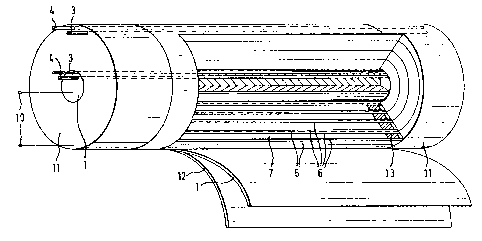
Figure 1 shows, in a perspective representation,
the winding of an anion and a cation exchanger membrane
6 and a central electrode 1, a dilution chamber 7 with a
spacer 13 arranged at the end face, a concentrate chamber
with spacer 5, a concentrate distribution system or
removal system 4, a distribution system for the solution
to be treated or a water removal system 3, the outer
counterelectrode 1 which is encased by a polymeric jacket
12, end-face epoxy-resin blocks il and electrical connec-
tions 10 to the direct-current source.
Figure 2 shows a preferred embodiment of the
inner clamping device in a cross section perpendicular to
its longitudinal dimension. The clamping device is
composed of a membrane compression system 2 made of two
parts, between which a sealing material 9 is arranged,
and the nation and anion exchanger membranes 6 are passed
between the sealing material and one of the parts of the
membrane compression system in each case. Hy pressing the
parts of the membrana compression system 2 together by
means of screwing, the dilution chamber is tightly sealed
off. The figure furthermore shows recesses on both parts
of the membrane compression system 2 which are matched to
the distribution ar removal system 3 of the dilution
chamber in such a way that said system can also be firmly
clamped by the clamping device. Furthermore, one of the
two parts of the membrane compression system 2 has a
- to -
recess for receiving the concentrate distribution system
or removal system 4. The position of the concentrate
chamber spacer 5 is furthermore indicated by a broken
line.
Figures 3 and 4 show a cross section perpen-
dicular to the longitudinal axis of the wound module, the
entire cross section being shown in Figure 4 and only a
portion of the cross section being depicted in Figure 3
with the membrane windings omitted in order to show the
clamping devices and the constriction of the electrodes
with better clarity. The figures show the central elec-
trode or outer counterelectrode 1, the two-part membrane
compression system 2, the distribution or removal system
3 of the dilution chamber 7, the distribution or removal
system 4 of the concentrate chamber, the concentrate
chamber spacer 5, the ion exchanger membranes 6, the
mountings 8 for the outer clamping devic~ and the sealing
material 9 between the two parts of the membrane compres-
sion system.
Figure 5 shows, in a cross section perpendicular
to the longitudinal axis of the wound module, a central
electrode 1, which is filled with a polymer and has a
recess for receiving the inner synthetic resin block 2,
an anion and a cation exchanger membrane 6, whose spiral
windings enclose a dilution chamber 7 and a concentrate
chamber containing spacer 5, an inner and an outer
synthetic resin block 2 in which the inner and the outer
edges, respectively, of the ion exchanger membranes 6 and
of the spacer 5 as well as the distribution system for
the solution to be treated or the water removal system 3
are anchored, an outer countdrelectrode 1 which is
matched to the spiral winding and has passage openings,
a concentrate distribution or removal system 4, and a
pressure-resistant polymeric jacket and/or a pressure
95 resistant steel tube 12.
In Figures 1-5, the concentrate chamber is shown
with a spacer 5 for reasons of better clarity. Of course,
the spacer may, if need be, be absent or, preferably,
J
- 11 -
both the concentrate chamber and the diluate chamber may
have a spacer.
In Figures 1-5, parts having interchangeable
functions, namely the electrodes 1, the distribution or
removal systems 3 and 4 and the ion exchanger membranes
6, are in each case provided with identical reference
symbols. As already mentioned above, the central elec-
trode can be chosen as anode and the outer counter-
electrode as cathode or the central electrode as cathode
and the outer counterelectrode as anode. The arrangement
of the ion exchanger membranes results from the choice of
the electrode, the diluate chamber being bounded
logically in each case by the anion exchanger membrane in
the direction of the anode and by the cation exchanger
membrane in the direction of the cathode. The diluate
flow and the concentrate flow can be fed from the inside
outwards or from the outside inwards independently of one
another, i.e. in normal flow or in caunterflow. Corres-
pondingly, the distribution system can be arranged in
each case on the inside and the removal system on the
outside, or vice versa.