Note: Descriptions are shown in the official language in which they were submitted.
CA 02096155 2000-02-28
REFLECTIVE AND TRANSMISSIVE DOCUMENT READING
APPARATUS AND A METHOD OF READING A DOCUMENT
The present invention relates to a reflective and transmissive document
reading apparatus and a method of reading the original document, and more
particularly, to a reflective and transmissive document reading apparatus and
a
method of reading the document, wherein image information such as characters
and patterns on an original document of light-reflective or light-transmissive
type
is converted into digital signals for every picture element or pixel, so as to
transmit the digital signals into various kinds of image-processing apparatus.
In
addition, the present invention is directed to an improved scanner for use in
these
apparatus, the scanner including reflective/transmissive document mode
discriminating means for realizing an easy selection of document mode by means
of a simple switching means.
Conventional document reading pickup apparatus (scanners) are
generally directed to read either a reflective or transmissive document.
Alternatively, there have been apparatus which are capable of functioning to
read
both reflective and transmissive documents. Nevertheless, such apparatus
require
a rather troublesome handling so as to attach and/or remove associated parts
such
as a reading unit, a document presser, etc., every time the reading mode is to
be
changed between a reflective document mode and a transmissive document mode.
Referring to the drawings, one example of such an apparatus will be
described. Figures lA to 1C are perspective views showing the schematic
appearance of a conventional document reading apparatus. Figures lA, 1B and
1C show a document pressing plate 32, a transmissive document reading unit 33,
and a scanner body 31, respectively. Figures 2A and 2B are perspective views
showing manners of attachment and detachment of parts in a conventional
scanner. Specifically, Figure 2A shows a manner of detaching a document cover
-1-
CA 02096155 2000-02-28
22 from a scanner body 31, whereas Figure 2B shows a manner of attaching a
lamp unit 36 to a scanner body 31. In the figure, reference numeral 35
designates
attachment holes for lamp unit 36.
Since attachment and detachment of these parts are considerably
troublesome and complicated, the present applicant hereof has presented
Japanese
Patent Application Laid-Open sho 61 No. 21672, in which an optical path-
changing mechanism which allows an easy selection of reading modes between a
reflection mode and a transmission mode. In this mechanism, a light source is
provided only on a side in which a light receiving means is disposed while a
series
of mirrors are used to create a first optical path system for introducing
transmitted
light to the light receiving means and a second optical path system for
introducing
reflected light to the light receiving means. In this arrangement, there is
provided
a switching means which works such that, if one of the two modes is selected,
the
other mode is shut down. In this case, as the scanning mode is changed over, a
driver means is activated to move a light-diffusing plate to advance or
retract. The
light-diffusing plate is shifted to insert between the light source and a
document
when transmission mode is selected, so that light emitted from the
illuminating
lamp may be scattered to create uniform light entering the transmissive
document.
As described above, the conventional reflective and transmissive
document reading apparatus (scanner) as shown in Figures lA to 1C and Figures
2A and 2B, would necessitate attaching and/or removing operations, of a
reflective document presser or document cover required for reading a
reflective
document, or of a transmission unit or a lamp unit for transmission mode
required
for reading a transmissive document in addition to a switching operation,
every
time the mode of reading is to be changed from a reflective document mode into
a
transmissive document mode, or vice versa. For these reasons, the conventional
apparatus have suffered from great deterioration of the scope of use of the
reading
apparatus and the operability thereof.
-2-
CA 02096155 2000-02-28
With regard to a mechanism proposed in Japanese Patent Application
Laid-Open sho 61 No. 21672, since one of the optical path systems is selected
by
changing over the position of a minor, the operation is simple, but two
optical
path systems are required so that the space occupied by these in the apparatus
becomes great, and the structure of the apparatus could not help becoming
slightly
complicated.
To deal with these problems, in recent years, there has been known a
system which includes a basic apparatus of a reflective document reading unit
comprising a CCD (charge-coupling device as used for a light receiving device)
for reflective documents, a scanner light source and an opaque document
pressing
cover; and to which an optional unit including a CCD for transmissive
documents
can be attached in place of the document pressing cover after removal thereof.
In
this case, if the unit for transmissive document is attached, a switch is
operated to
recognize the attachment of the unit, so as to change over the mode of the
scanner
into transmissive document mode. On the other hand, when the apparatus is used
in reflective document mode, the document pressing cover must be attached
after
the removal of the unit for transmissive documents in the order opposite to
that
described above.
In the above case, if the unit for transmissive documents remains
attached, the aforementioned switch also remains in operation. This prohibits
the
change in the unit for reflection documents. Accordingly, when the apparatus
is
used in reflection document mode, it is necessary to cancel the switch by
removing the unit for transmissive documents, or by any other way, whatever it
may be.
However, practical use of scanning would often demand repeated
changes of the mode between reflective and transmissive document modes. In
such cases, the attachment and detachment of the unit and the document presser
-3-
CA 02096155 2000-02-28
give rise to considerable intricacy. Accordingly, simplification of its
handling has
been earnestly desired.
Now, with regard to scanning color documents, the aforementioned
Japanese Patent Application Laid-Open sho 61 No. 21672 teaches a method.
When a color document is scanned, a plurality of light sources such as a red
(R)
light source 7a, a blue (B) light source 7b and a green (G) light source 7c,
etc. are
required. In this case, because the incident angles of different colored light
beams
are different from one another, when a transmissive document is to be read, a
diffusing plate 103 is required to scatter the light beams in order to measure
the
difference of the beams in their incident directions. More specifically, in
accordance with the technology proposed in the publication, light beams
emitted
from light sources 7a to 7c are scattered by diffusing plate 103 to irradiate
a
document 14, whereby the transmitted light from the document is passed through
a reflection mirror lOc and a lens 1 lb to be read by light receiving element
23b of
a CCD, as shown in Figure 3.
In the reading of color documents, one method of color-separation of
light into R, G and B components can be effected using different filters.
Specifically, Japanese Patent Publication sho 62 No. 62101 discloses a method
in
which the reflected light from a color document is passed through filters to
read
information having particular wave length ranges, whereby the color document
is
separated in color. However, in the color-separation method by means of
filters,
because different color light beams such as ones of R, G and B irradiate the
document in different directions, light-intensity among the different color
light
beams will become unbalanced, particularly when a portion of the document
comes up (shown by 14b) away from a reference surface 14a, so that the
reproduction of color may be degraded (particularly, a shadowy portion is
subject
to be colored by separated color light).
-4-
CA 02096155 2000-02-28
Moreover, when, as shown in Figure 5, for example, a three-
dimensional, gray-colored (achromatic) solid body as an object 50 is scanned
in a
color scanner for reading reflective original objects or documents in which
the
conventional three light sources of R, G and B are employed, light emitted
from
red light source 7a is partially reflected on the object to be incident on CCD
23a
while the reflection of light emitted from green light source 7b and blue
light
source 7c does not go into CCD 23a. As a result, despite that object 50 itself
is
gray, the object might be picked up as a red image. Generally speaking, a
shadowy portion is easily colored.
Here, in Figure 5, reference numerals 8, and 101 respectively designate
a contact glass and an optical unit including a mirror l0a and a lens 11 a.
The present invention has been achieved under consideration of the
problems of the prior art means described above, and it is therefore a main
object
of the present invention to provide a reflective and transmissive document
reading
apparatus which is handled in a simple manner and improved in its
configuration
as compared with prior art apparatus as well as to provide a method of reading
original documents.
Particularly, with regard to the apparatus, it is an object of the present
invention to provide a scanner including a reflective/transmissive document
mode
discriminating means which allows automatic switching of the reading modes
while a transmissive document unit remains attached to the scanner, by
discriminating the presence or absence of a document presser without the
necessity of effecting troublesome attachment and detachment of the units.
It is another object of the present invention to provide a document
reading light source unit which allows reading of both reflective and
transmissive
color documents, without the necessity of a diffusing plate.
It is still another object of the invention to provide a reflective
document reading light source unit which can improve color reproduction
-5-
CA 02096155 2000-02-28
performance for an achromatic solid object or a reflective document even when
portions of the original solid object or document rise or come up.
In order to achieve the above objects, the present invention will be
constructed as follows.
That is, the present invention has been attained to achieve the above
objects, and a first aspect and feature of the invention resides in that a
scanner is
provided with means for reading both reflective and transmissive documents,
comprising:
a pair of CCD sensors, one of which is for reflection mode to read
reflective documents, and the other of which is for transmission mode to read
transmissive documents, disposed respectively on a side of a light source, and
on
the opposite side thereto, with a document table therebetween; and
a reflective/transmissive document mode discriminating means
including switching means wherein, when a light source is turned on, a
judgment
is made on whether or not light to be transmitted is blocked by a document
pressing sheet, and based on the judged result, circuits of said CCD sensors
are
automatically changed over between the one for transmission mode and the other
for reflection mode.
A second aspect and feature of the invention lies in that a reflective and
transmissive document reading apparatus comprises:
a transmissive document reading unit disposed above a scanner body of
the document reading apparatus, wherein a reading window disposed in said
transmissive document reading unit is equipped with a blocking member or a
diffusing plate in an attachable and detachable manner, said blocking member
being for preventing light from entering said transmissive document reading
unit,
and said diffusing plate being for scattering incident light so as to
introduce
uniform light into said transmissive document reading unit.
-6-
CA 02096155 2000-02-28
A third aspect and feature of the invention is in that a reflective and
transmissive document reading apparatus comprises:
a transmissive document reading unit disposed above a scanner body of
the document reading apparatus, wherein a reading window disposed in said
transmissive document reading unit is equipped with a blocking member or a
diffusing plate in an attachable and detachable manner, said blocking member
being for preventing light from entering said transmissive document reading
unit,
and said diffusing plate being for scattering incident light so as to
introduce
uniform light into said transmissive document reading unit; and
detecting means of said blocking member or said diffusing plate for
detecting the presence or absence of the attachment of said blocking member or
said diffusing plate and transmitting the obtained information to a main
control
section of said scanner body.
In an apparatus according to the second and third aspects and features,
it is effective that the blocking member comprises an external light-blocking
sheet
or a light-blocking mat.
A fourth aspect and feature of the invention is provided by a reflective
and transmissive document reading apparatus comprising:
a lamp for a transmissive document, to irradiate a transmissive
document;
a blocking member that can be stretched out and wound up for
reflecting light emitted from an illuminating lamp of a scanner body; and
both said lamp and blocking member being disposed above said
scanner body of the document reading apparatus.
A fifth aspect and feature of the invention resides in a method of
reading reflective and transmissive documents, wherein use is made of a
reading
apparatus comprising: a transmissive document reading unit disposed above a
scanner body of the document reading apparatus, and a diffusing plate that can
be
7_
CA 02096155 2000-02-28
attached and detached, for scattering incident light so as to introduce
uniform light
into said transmissive document reading unit, comprising the steps of:
setting the apparatus in a transmission reading mode;
detecting the presence or absence of said diffusing plate, by moving an
illuminating lamp by means of an optical unit that moves integrally with said
illuminating lamp of said scanner body;
judging automatically based on the detected result whether the
apparatus should be operated in transmission mode or reflection mode; and
thereafter,
scanning a document in the selected mode.
A sixth aspect and feature of the invention lies in that a light source
unit for reading reflective and transmissive documents provided for a reading
apparatus of reflective and transmissive documents, comprising:
a light source;
dichroic mirror means for creating a desired color light by color-
separating light emitted from said light source; and,
a dielectric beam sputter for reflecting and transmitting the created
desired color light, so that the reflected light is irradiated on a reflective
document
while the transmitted light is irradiated on a transmitted document.
In the above unit, it is effective that the dichroic mirror means
comprises a plurality of dichroic mirrors each creating a light beam having a
desired color, and the light beams each having a desired color are aligned in
a
direction to irradiate a reflective document.
A seventh aspect and feature of the invention is provided by a light
source unit for reading reflective documents, provided for a reflective
document
reading apparatus, comprising:
a light source; and
_g_
CA 02096155 2000-02-28
a plurality of dichroic mirrors each creating a light beam having a
desired color by color-separating light emitted from said light source,
wherein said light beams each having a desired color are aligned in a
direction to irradiate a reflective document.
An eighth aspect and feature of the invention resides in a color scanner
for reading reflective documents comprising:
a plurality of light sources;
two or more elements of half mirrors or dichroic mirrors incorporated
in a light source unit for aligning in a direction light beams emitted from
said
plurality of light sources;
one or more elements of mirrors incorporated in said light source unit
for introducing said light beams to a reading line while keeping said light
beams
incident thereto with an identical angle; and,
a blocking member disposed in the nearest light source from said
reading line for blocking out unnecessary light.
In the optical unit for the above scanner, the plurality of light sources
may use any of the R, G and B light sources or white light sources, and it is
also
effective that the darkest light source is disposed in the nearest position
from the
pickup line while the brightest light source is disposed in the farthest
position
therefrom.
The present invention is provided by the above configurations, in the
structures described in the first to fifth aspect of the invention, the
apparatus has a
transmissive document reading unit disposed above a scanner body of the
document reading apparatus while a blocking member or a diffusing plate may be
attached and detached in correspondence with transmissive and reflective
modes,
and further the apparatus includes detecting means for detecting the presence
of
the member. Therefore, it is possible to perform scanning corresponding to
mode
change with only a simple operation.
_g_
CA 02096155 2000-02-28
For example, the scanner light source and the CCD sensor for use in
transmissive mode are utilized as a means for determining the switching
between
the reflective document unit and transmissive document unit. In this case,
when
the document pressing sheet is attached, light emitted from the scanner light
source is blocked out and cannot reach the CCD sensor for transmissive mode,
therefore, the transmissive document mode is disabled while the reflective
document mode becomes valid. On the other hand, unless the document pressing
sheet is attached, the situation becomes the opposite. Thus, it is possible
for the
apparatus to be changed over between both modes simply by inserting or
retracting the document pressing sheet, without the necessity of providing an
individual sensor for detecting the presence of the document pressing sheet,
or
without the necessity of attaching or detaching an optional transmissive
document
unit.
In addition, the apparatus is provided with a lamp for transmissive
documents and a blocking member that can be stretched out and wound up, both
disposed above the scanner, so that it is possible to utilize the optical
system
incorporated in the scanner body to effect scanning in transmission mode.
Accordingly, parts can be markedly reduced in number.
Moreover, when, with no blocking member, a diffusing plate is inserted
into between the transmissive document reading unit and the scanner body, it
is
possible to automatically change over the mode between transmissive mode and
reflective mode based on examination of the presence of the diffusing plate.
In the structures in accordance with the sixth to eighth aspects and
features, light emitted from a light source is color-separated by, for
example, a
dichroic mirror to create desired color light and then the desired color light
is
transmitted and reflected through a dielectric beam sputter, so that the
reflected
light is irradiated on a reflective document while the transmitted light is
irradiated
-10-
CA 02096155 2000-02-28
on a transmitted document. Accordingly, it is possible to read both reflective
and
transmissive documents without the necessity of a diffusing plate.
Here, in the present invention, when a plurality of dichroic mirrors are
provided to create a plurality of light beams each having a desired color, and
the
light beams having a desired color obtained from respective dichroic mirrors
are
aligned in a direction to irradiate a reflective original, it is possible to
improve
color reproduction performance for a document or a solid object, even one
having
unevenness or swell.
In addition, in the present invention, illuminating light is color-
separated by a plurality of dichroic mirrors to create a plurality of desired
color
light beams, and the light beams having desired colors obtained from
respective
dichroic mirrors are aligned in a direction to irradiate a reflective
document.
Accordingly, the beams having desired colors can be irradiated on the
reflective
color document with the angle of all the irradiating beams being coincident,
so
that it is possible to improve color reproduction performance for an original
document, even having unevenness or swell.
Moreover, in the present invention, light beams emitted from a plurality
of light sources in the optical unit are aligned in a direction, while, upon
irradiation onto a pickup or reading line, the nearest light source from the
reading
line is provided with a blocking member to block out unnecessary light. With
this
arrangement, even when a solid achromatic object is scanned, it is possible to
prevent the shadowy portion of the object from coloring in its reproduction.
Figure lA is a perspective view showing a document pressing plate of a
prior art document reading apparatus;
Figure 1B is a perspective view showing a transmissive document
reading unit of a prior art document reading apparatus;
Figure 1C is a perspective view showing a scanner body of a prior art
document reading apparatus;
-11-
CA 02096155 2000-02-28
Figure 2A is a perspective view illustrating a manner of detaching a
document cover from a prior art scanner body;
Figure 2B is a perspective view illustrating a manner of attaching a
lamp unit to a prior art scanner body;
Figure 3 is a structural illustration schematically showing a
transmissive color document reading means of a prior art;
Figure 4 is a schematic illustration for explaining imbalance of light
intensity among light beams having different colors in the means shown in
Figure
3 when a solid object or original document has unevenness;
Figure 5 is an illustration showing an arrangement of prior art means in
which an achromatic solid object is subject to a reading operation using three
light
sources;
Figure 6A is a perspective view showing a document reading apparatus
for reflective and transmissive type documents with a transmissive document
reading unit being closed, in accordance with the invention;
Figure 6B is a perspective view showing an appearance of a document
reading apparatus for reflective and transmissive type documents in accordance
with the invention;
Figure 6C is a perspective view showing an inside structure of a
document reading apparatus for reflective and transmissive type documents in
accordance with the invention;
Figure 7 is a schematic diagram for explaining a switching means of
scanner units in a document reading apparatus for reflective and transmissive
type
documents in accordance with the invention;
Figure 8 is a schematic block diagram showing an embodied
configurations using a blocking member among document reading apparatus for
reflective and transmissive type documents in accordance with the invention;
-12-
CA 02096155 2000-02-28
Figure 9A is a schematic illustration showing a reflection-reading
operation in the apparatus shown in Figure 8;
Figure 9B is a schematic illustration showing a transmission-reading
operation in an apparatus shown in Figure 8;
Figure l0A is an illustration showing an embodiment of a blocking
member for use in the invention;
Figure lOB is an illustration showing another embodiment of a
blocking member for use in the invention;
Figure 11 is a schematic illustrative diagram showing another
embodiment of an apparatus shown in Figure 8;
Figure 12A is an illustrative view showing an elemental structure of a
reflective and transmissive document reading apparatus employing a pair of
lamp
units according to the present invention;
Figure 12B is an illustration showing a structure of a blocking member
that can be stretched out and wound up for use in a reflective and
transmissive
document reading apparatus employing a pair of lamp units according to the
present invention;
Figure 12C is an illustration showing the operation of the blocking
member shown in Figure 12B;
Figure 13 is a block diagram showing a controlling circuit of a scanner
and its associated parts for executing a method of the present invention in
which a
diffusing plate is used to read reflective and transmissive documents, and
explaining the operation thereof;
Figure 14 is a schematic illustration showing a basic arrangement of
optical units and other components for executing a method of the present
invention in which a diffusing plate is used to read reflective and
transmissive
documents;
-13-
CA 02096155 2000-02-28
Figure 15A is an illustration showing a state of optical units in an
apparatus shown in Figure 14, the state, based on which the pickup mode of the
apparatus is determined as to be in reflective mode;
Figure 15B is an illustration showing a state of optical units in an
apparatus shown in Figure 14, the state, based on which a reading operation in
reflective mode is started;
Figure 16A is an illustration showing a state of optical units in an
apparatus shown in Figure 14, the state, based on which the reading mode of
the
apparatus is determined as to in transmissive mode;
Figure 16B is an illustration showing a state of optical units in an
apparatus shown in Figure 14, the state, based on which a reading operation in
transmissive mode is started;
Figure 17 is a flowchart for explaining the reading method for reading
reflective and transmissive documents of the present invention associated with
the
embodiment shown in Figures 13 to 16B;
Figure 18 is a structural view showing a scanner provided with an
embodiment of light source units for reading reflective and transmissive
documents in accordance with the invention;
Figure 19 is a structural view showing a scanner provided with an
embodiment of a light source unit for reading reflective documents in
accordance
with the invention;
Figure 20 is a structural view showing a scanner provided with a
variational embodiment of a light source unit shown in Figure 19;
Figure 21A is a schematic illustrative view showing a structural
example of a color scanner for use in a reflective document reading apparatus
of
the invention;
Figure 21B is a schematic illustrative view showing a variational
embodiment of a color scanner shown in Figure 21A;
-14-
CA 02096155 2000-02-28
Figure 22A is a schematic illustrative view showing another variational
embodiment of a color scanner shown in Figure 21A;
Figure 22B is a schematic illustrative view showing a variational
embodiment of a color scanner shown in Figure 22A;
Figure 23A is a schematic illustrative view showing still another
variational embodiment of a color scanner shown in Figure 21A;
Figure 23B is a schematic illustrative view showing a variational
embodiment of a color scanner shown in Figure 23A;
Figure 24A is a schematic illustrative view showing another variational
embodiment of a color scanner shown in Figure 22A; and
Figure 24B is a schematic illustrative view showing a variational
embodiment of a color scanner shown in Figure 24A.
The present invention will hereinafter be described in detail with
reference to the accompanying drawings. First of all, Figures 6A to 6C are
perspective views showing a schematic appearance of a document reading
apparatus for reflective and transmissive type documents equipped with a
blocking member in accordance with the present invention. In Figure 6A, the
apparatus is shown with a transmissive document reading unit 2 being closed.
Here, a reference numeral 1 designates a main body scanner of the document
reading apparatus.
Figure 6B is a perspective view showing an appearance of a main body
scanner. In Figure 6B, a reference numeral 1 indicates a scanner body, or a
unit
for reflective documents including a reading means for reflective documents. A
reference numeral 8 designates a document table, generally formed with glass.
The unit for reflective documents, or scanner body 1 axially supports a
transmissive document reading unit 2a as to be a means for reading
transmissive
documents through an appropriate joint member 60 so that the unit 2a may be
opened and closed, and the unit 2a is connected to the unit for reflective
-15-
CA 02096155 2000-02-28
documents, or scanner body 1 through a cable 45 for signal transmission. A
document pressing sheet 15b of an opaque material is fit to a pickup window 3
of
transmissive document reading unit 2a in such a manner that the sheet can be
manually attached and detached in directions of arrows A and B. This fact that
the document pressing sheet is formed with an opaque material and arranged in
an
attachable and detachable manner, is effective in the invention, to allow an
easy
change-over between reflection and transmission modes, as will be described
hereinafter. In the figure, the element denoted by 43 is a control panel of
scanner
1.
Figure 6C is a view showing configurations including the inside of
transmissive document reading unit 2 in a more specific manner. In the figure,
a
reference numeral 4 designates an external light-blocking sheet as a means for
blocking member, which is attached to reading window 3 when a reflective
document is to be read. An attachment guide for the attachment is shown at 5,
along which external light-blocking sheet 4 is provided movable in directions
of
arrows shown in the figure.
A detector 6 is disposed on a side end of the reading window 3. The
detector 6 is a means for detecting whether or not an end of external light-
blocking sheet 4 reaches the position of detector 6, or the presence or
absence of
the blocking member and based on the result, transmitting the information, to
a
main controlling section in the scanner body. The provision of detector 6
allows
an automatic set-up of a pickup mode between transmission and reflection
modes.
An attachment angle 37 is provided as a jig for attaching transmissive
document reading unit 2 to scanner body 1 of the document reading apparatus.
Next, configurations of respective units for reflection and transmission
type documents will be explained with reference to the drawings.
Figure 7 is a schematic diagram showing switching means between
both units in the scanner of the invention.
-16-
CA 02096155 2000-02-28
In Figure 7, transmissive document reading unit 2 with document
pressing sheet 15b shown in Figure 6B is illustrated above a dashed and dotted
line, while scanner body 1 provided with document table 8 mainly for the unit
of
reflective document is shown below the dashed and dotted line.
In Figure 7, a document is designated by a numeral 9 or 14, depending
on its type. That is, reference numerals 9 and 14 are allotted for reflective
and
transmissive documents, respectively. A CCD sensor 23a for reflective document
9 and another CCD sensor 23b for transmissive document 14 are disposed
respectively on opposite sides of document table 8 as shown in Figure 7. A
means
for discriminating connection with transmission mode (which will be expressed
by
transmission connection discriminating means) indicated by 49 is provided so
as
to allow CCD sensor 23b to automatically discriminate the presence of document
pressing sheet 15b to change over a circuit change-over switch 41 when a power
supply (not shown) for a light source 7 for scanner is turned on. In other
words,
the provision of the means 49 will afford a selection of reading modes between
transmission and reflection modes. An element shown by 47 is an image signal
amplifier for processing sensor signals from CCD sensor 23a or 23b.
Now, referring to Figure 7, the operation of an embodied apparatus of
the invention will be described.
When the power source for light source 7 is turned on, light source 7
will emit light. In this case, when document pressing sheet 15b is attached on
the
side of transmissive document reading unit 2, the light from light source 7
will be
blocked out and cannot reach CCD sensor 23b since document pressing sheet 15b
is formed with an opaque material. Therefore, transmission connection
discriminating means 49 determines that transmissive document reading unit 2
is
invalid, and circuit change-over switch 41 is changed over into the reflective
document mode, so that light source 7 operates in reflection mode.
-17-
CA 02096155 2000-02-28
On the other hand, if document pressing sheet 1 Sb is not attached, the
light emitted from light source 7 is received by CCD sensor 23b, therefore
transmission connection discriminating means 49 determines that transmissive
document reading unit 2 is valid in this case. Accordingly, circuit change-
over
switch 41 is changed over into the transmissive document mode, so that light
source 7 operates in transmission mode.
Next, there will be provided description of the operation of reading a
document in the invention.
As shown in Figure 7, an original 9, or 14 is put on document table 8
for picking up the information thereon. In this case, with a document 14, that
is, a
transmissive document, document pressing sheet 15b is detached, so that
circuit
change-over switch 41 is changed into the transmission mode. That is, a
circuit
including CCD sensor 23b for transmission mode will be formed. Therefore,
light
emitted from light source 7 transmits through document 14 and is received by
CCD sensor 23b for transmission mode, proceeding in a light path Y shown by a
broken line. Then the signal is sent through switch 41 to image signal
amplifier
47 for processing. In contrast, with a document 9 or reflective document,
document pressing sheet 15b is attached, so that circuit change-over switch 41
is
changed into the reflection mode. That is, a circuit including CCD sensor 23a
for
reflection mode will be formed. Therefore, light emitted from light source 7
is
reflected on document 9 and is received by CCD sensor 23a for reflection mode,
proceeding in a light path X shown by a solid line. Then the signal is sent
through
switch 41 to image signal amplifier 47 for processing.
Figure 8 is an illustrative diagram schematically showing an
embodiment of the reflective and transmissive document reading apparatus of
the
invention, in order to illustrate the case in which a blocking member is
engaged.
This case will be described hereinafter.
-18-
CA 02096155 2000-02-28
First, in Figure 8, the upper transmissive document reading unit 2 and
the lower scanner body 1 correspond respectively to the components shown in
Figures 6A to 6C described above. There are a document table 8 provided
between scanner body 1 and transmissive document reading unit 2, a reading
window 3 equipped with an attachment guide 5 shown in Figure 6C disposed on
the side of the transmissive document reading unit 2, and a detector 6 for
detecting
the presence or absence of external light-blocking sheet 4 shown in Figure 6C
disposed on an end of reading window 3.
In Figure 8, numerals 9 and 14 designate documents. Of these, 9
indicates a reflective document and 14 denotes a transmissive document.
In Figure 8, transmissive document reading unit 2 and scanner body 1
include respective optical systems for performing a reading operation with a
common illuminating lamp 7. Specifically, transmissive document reading unit 2
is provided, in the order of light progressing direction along a transmission
optical
path, with a mirror lOc, a mirror lOd, a lens l lb and a charge-coupling
device
(CCDb) 23b for converting the transmitted light into electric signals,
respectively.
On the other hand, scanner body 1 is provided, in the order of light
progressing direction along a reflection optical path, with a mirror 10a, a
mirror
lOb, a lens 1 la and a charge-coupling device (CCDa) 23a for converting the
reflected light into electric signals, respectively.
Further, mechanism controllers 25b and 25a are provided as means for
controlling mechanisms of document reading operation on the side of
transmissive
document reading unit 2 and the side of scanner body 1, respectively.
As means for controlling the system totally, there is incorporated in
scanner body 1 a main controlling section 25 comprised of a central processing
unit (CPU) including a publicly known program memory, a timing circuit, a
correction circuit, etc. The main controlling section 25 functions to give an
instruction of the original document type information transmitted from a
detector
-19-
CA 02096155 2000-02-28
6 which produces the output information based on judgment of whether or not
there is a blocking member. With this instruction given by main controlling
section 25, an illuminating controlling section 34 of illuminating lamp 7 and
the
mechanism controllers 25a, 25b are controlled. There is provided an AID
converter 24 which executes A/D conversion of image date photoelectrically
converted when the data is transmitted from CCDa 23a or CCDb 23b to main
controlling section 25. There are also provided an interface 25d for
processing and
communicating input/output signals with the outside, a memory 25f for storing
information externally, power supply 25e for supplying electric power, and
other
necessary components.
Next, with reference to schematic illustrations shown in Figures 9A and
9B, the operation of reading in each mode will be described in accordance with
the embodiment of the reading apparatus configuration as shown in Figure 8.
First, Figure 9A shows a mode in which a reflective document is read
in. Light emitted from illuminating lamp 7 incorporated in scanner body 1
reaches reflective document 9 put between transparent table 8 mounted on the
top
of scanner body 1 and external light-blocking sheet 4 attached on reading
window
3 of transmissive document reading unit 2, and is reflected thereon. The
reflected
light (indicated by 12) including character and/or image information of the
original document is directed into scanner body 1, and proceeds successively
from
reflective document 9 through mirror 10a, minor lOb and lens l la to CCDa 23a
(charge-coupling device) as shown by arrows in the figure. The light thus
arrived
is converted photoelectrically at CCDa 23a into electric signals, to be
transferred
to A/D converter 24 as shown in Figure 8.
On the other hand, Figure 9B shows a mode in which a transmissive
document is read in. In the case, external light-blocking sheet 4 has been
removed, and light emitted from illuminating lamp 7 incorporated in scanner
body
1 illuminates transmissive document 14 put between transparent table 8 mounted
-20-
CA 02096155 2000-02-28
on the top of scanner body 1 and reading window 3 of transmissive document
reading unit 2, and passes through the document to acquire character and/or
image
information of the document. The transmitted light (indicated by 13)
containing
character and/or image information of the document is directed into
transmissive
document reading unit 2, and proceeds successively from transmissive document
14 through mirror lOc, mirror lOd and lens l lb to CCDb 23b as shown by
arrows.
The light thus arrived is converted into electric signals at CCDb 23b, to be
transferred to A!D converter 24. Here, illustrative description of detector 6
will be
omitted as it has been described heretofore.
As described above, according to the invention, in place of a document
cover, a transmission unit, or a document pressing plate used in the prior
art, the
apparatus is equipped with a transmissive document reading unit 2 and an
external
light-blocking sheet 4 attachable and detachable for reading window 3 of the
unit
2, as well as detecting means including a detector 6 for detecting whether
external
light-blocking sheet 4 is inserted in the unit 2. or not. Accordingly, there
will be
no need for attachment or detachment of a document pressing plate, a document
cover or a transmissive document unit which would be required to be exchanged
in the prior art every time the type of document used is changed. In addition,
since reading modes corresponding to transmissive and reflective documents can
automatically be set up, the operativity of the reading apparatus is improved
and
becomes easy to handle.
Further, in using the thus arranged apparatus of the present invention, it
is possible to use as a blocking member a light blocking mat (OC mat) formed
with a material such as a sponge, in place of the aforementioned external
light-
blocking sheet 4. Figures l0A and lOB are illustrative views showing an
embodiment using such a mat, and Figures l0A and l OB are a perspective view
thereof and a side view thereof observed in a direction of arrow AA in Figure
1 OA.
-21 -
CA 02096155 2000-02-28
The perspective view of Figure l0A shows a state in which a light
blocking OC mat 15 is fit into OC mat attachment guide 16 while the
transmissive
document reading unit 2 is opened from scanner body 1. As shown in the AA-
direction view of Figure lOB, OC mat 15 has a sponge 15a applied thereto on
its
side in contact with a glass surface 3a of transmissive document reading unit
2,
and is provided with a detachment knob 30 to allow an easy detachment.
Here, with regard to the blocking member, the previously described
external light-blocking sheet 4 and the above-described OC mat 15 have been
referred to only for exemplary purposes, and any material can be used as long
as it
presents the equivalent effect.
It is possible to automatically change over the reading mode, without
using the detector 6, but by using a document pressing mat as a blocking
member,
for example, and judging attachment or detachment of the document pressing mat
with the help of an illumination reset switch of illuminating lamp 7 to turn
on
illuminating lamp 7.
More specifically, Figure 11 is a schematic illustrative diagram
showing an embodied configuration of a reflective and transmissive document
reading apparatus of the invention, in which a document pressing mat 1 Sb and
a
reset switch 25g are employed. In this embodiment, configurations and
operations
are nearly identical with those of the embodiment of Figures 8, 9A and 9B,
except
that a reset switch 25g is connected to a main controlling section 25 in place
of
detector 6 shown in the embodiment of Figures 8, 9A and 9B.
In this arrangement, when a reset switch 25g disposed on a key control
panel (not shown) of the pickup apparatus is pressed, illuminating lamp 7 is
turned
on. At this time, the presence or absence of a document pressing mat 15b
attached
in transmissive document reading unit 2 determines transmission of signal from
CCDb (charge-coupling device) 23b to main controlling section 25. More
explicitly, in the case, if no signal is transmitted from CCDb 23b to main
_22_
CA 02096155 2000-02-28
controlling section 25, light emitted from illuminating lamp 7 is blocked by
the
document pressing mat 15b, or judged as not to be in the transmission mode.
Therefore, the system is automatically changed over into the reflection mode,
and
signals from CCDa 23a are transmitted to main controlling section 25. In
contrast,
if there is no document pressing mat 15b, light emitted from illuminating lamp
7
directly passes into the inside of transmissive document reading unit 2, so
that a
signal indicating that the system is in transmission mode is transmitted from
CCDb 23b to main controlling section 25. Thus, the switching between reading
modes for reflective documents and transmissive documents can be carried out
automatically.
In the above-stated embodiment shown in Figures 8, 9A and 9B, or
Figure 1 l, the system is configured to perform a reading operation in such a
manner using a common illuminating lamp 7, a pair of arrangements each
comprised of an optical system, a photoelectric converting means and a
mechanism controlling means are provided symmetrically for respective sides of
transmissive document reading unit 2 and scanner body 1. But it is possible to
construct a total system to serve for reading in both modes, not using a pair
of
units each including the optical system and other components as stated above,
but
by providing a pair of light source lamps for reflection and transmission
modes
only with a single unit having an optical system and other components
incorporated in scanner body 1.
Specifically, Figures 12A to 12C are schematic illustrations showing an
embodiment of the reflective and transmissive document reading apparatus of
the
present invention using two lamp units. Figure 12A is an illustration showing
elemental components thereof, whereas Figures 12B and 12C are perspective
views showing a structure of a blocking member that can be stretched and wound
up for use in the apparatus shown in Figure 12A.
-23-
CA 02096155 2000-02-28
First, referring to Figure 12A, the structure of the member will be
described. Reference numeral 2a denotes a unit for transmission mode,
including
mainly a lamp 17 for transmission mode and a blocking member of a white paper
sheet 19 for reflection that can be stretched and wound up. A scanner body 1
is
provided with an illuminating lamp 18 for reflection mode, as well as with an
optical system, a photoelectrically converting means, a mechanism controlling
means, etc., similar to those in the above-described scanner body shown in
Figures
8, 9A and 9B, or Figure 11. In addition, the scanner body 1 is provided with a
main controlling section and its other supplemental components. The
configurations and way of operation are nearly equivalent to those already
described, so that no particular description will be repeated herein. Numerals
9
and 14 designate documents, and as stated above, 9 designates a reflective
document and 14 denotes a transmissive document. These documents 9 and 14
are inserted between transmissive document reading unit 2a and scanner body 1
to
be read.
Referring now to Figures 12A, 12B and 12C, operation of the thus
constructed reading apparatus will be described. At first, for the case in
which the
apparatus is operated in a transmissive document mode, in using a transmissive
document 14, the apparatus is operated as shown in Figure 12B, or with white
paper sheet 19 for reflection wound up, and light source lamp 17 for
transmission
mode turned on. It should be noted that reflective white paper sheet 19 is
provided with stretching means such as pulling strings 20, which are used in
the
reflection mode that will be described later.
In this case, light emitted from illuminating lamp 17 for transmission
mode passes through document 14 with no blocking member of white paper 19, so
that reading the operation is carried out by the optical system with other
components on the side of scanner body 1 while illuminating lamp 17 for
transmission mode is being moved.
-24-
CA 02096155 2000-02-28
On the other hand, for the case in which the apparatus is operated in a
reflective document mode, in using a reflective document 9, the apparatus is
operated as shown in Figure 12C with white paper sheet 19 for reflection being
stretched out, and illuminating lamp 18 for reflection mode being moved while
turned on. In this case, the white paper sheet 19 can be stretched out as a
blocking
member on the back side of document 9 or on the side of the unit for
transmission
mode 2a, by drawing pulling strings 20. With this arrangement, the reading
operation is then carried out, for example, by an operation similar to the
reading
operation executed in the reflection mode.
In the above case, although a reflective white paper sheet 19 that can be
stretched and wound up is employed as a blocking member, any material other
than white paper, such as a strip-like fabric fine in texture, may be used as
long as
it has light-blocking ability and reflective characteristic.
In a conventional apparatus, for example, shown in Figures 2A and 2B
in which original cover 22 and lamp unit 36 are provided as separated parts,
the
original cover 22 for reflection mode and the lamp unit 36 for transmission
mode
should be attached to or detached from the main body every time the document
mode is to be switched. But the above-described structure shown in Figures
12A,
12B and 12C can all at once eliminate such troublesome handling. In a word, in
the structure shown in Figures 12A, 12B and 12C it can be considered that the
conventional document cover 22 would incorporate the lamp unit 36 for
transmission mode, and also be provided with a blocking member that may be
used in the reflection mode. Therefore, parts can be reduced in number and
handling can be simplified. In addition, the lamp 17 for transmission mode
does
not require as great a current for light intensity adjustment as the lamp unit
36 in
the conventional apparatus does, therefore energy saving can also be expected.
Any of the embodiments exemplarily described above uses a blocking
member together with a detector or by making use of an on-and-off operation of
-25-
CA 02096155 2000-02-28
an illuminating lamp, to thereby automatically achieve switching between
reflection mode and transmission mode. Next, an embodiment of the invention
will be described with reference to the drawings which uses, in place of a
blocking
member, a diffusing plate for scattering transmission light to make uniformly
defused light.
This embodiment comprises, as will be referred to, two optical units for
reflection and transmission modes. In this respect, the embodiment is similar
to
the first embodiment described above, but differs from the first embodiment in
use
of a diffusing plate for changing reading modes.
Specifically, Figure 13 is a block diagram for explaining a controlling
circuit and the operation thereof, of a scanner and its associated parts used
in the
embodiment. As shown in Figure 13, a photoelectrically converting means CCDa
23a (for reflection mode) and CCDb 23b (for transmission mode) are both
connected to an A/D converting section 25u through respective switches SWa and
SWb. The AID converting section 25u in turn is connected to a scanner
controlling circuit 25s to transmit the data to a main controlling section 25.
On
the other hand, scanner controlling circuit 25s is provided with a means for
generating a signal "REFL". The "REFL" indicates "reflection", and if REFL =
" 1 ", it represents a reflection mode whereas if REFL = "0", it represents a
transmission mode. In practice, when a diffusing plate as will be referred to
is
absent, REFL = "1" holds, and if there is a diffusing plate, REFL = "0" holds.
The REFL port is connected to a gate of switch SWa as well as to a
gate of switch SWb via an invertor (NOT circuit) 25t.
As constructed above, if scanner controlling circuit 25s launches a
signal REFL=" 1 ", for example, switch SWa is turned on, and the gate of
switch
SWb receives a signal through invertor 25t that indicates no attachment of a
diffusing plate and consequently switch SWb will be turned off. Therefore, in
this
case, the output of CCDa 23a, or more specifically, the output of the CCD
sensor
-26-
CA 02096155 2000-02-28
for reflection pickup mode, is inputted into A/D converting section 25u, so
that the
data is sent to main controlling section 25.
In contrast, if scanner controlling circuit 25s launches a signal
REFL="0", switch SWa is turned off, and the gate of switch SWb receives a
signal
through inventor 25t that indicates attachment of a diffusing plate and
consequently, switch SWb will be turned on. Therefore, in this case, the
output of
CCDb 23b, or more specifically, the output of the CCD sensor for transmission
pickup mode, is inputted into A/D converting section 25u, so that the data is
sent
to main controlling section 25.
Next, a reading method of reflective and transmissive documents using
the means described above will be described in a specific manner with
reference
to the drawings.
Figure 14 is a schematic illustrative view showing a basic arrangement
of optical units and other components used in the above means.
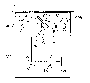
In Figure 14, reference numerals 101 and 102 designate an optical unit
for reflection mode and another optical unit for transmission mode,
respectively.
These optical units are basically the same as those optical units for scanner
body 1
and transmissive document reading unit 2 shown in Figure 8, Figures 9A and 9B
and Figure 11. Therefore, identical reference numerals are allotted to
identical
parts. Reference numerals 7 and 8 designate an illuminating lamp and a table
(made from glass), respectively, to which like numerals are allotted as
before. On
the other hand, numeral 100 denotes a portion of a cabinet body of the pickup
apparatus into which table 8 of glass is fit.
A point A indicates a home position for illuminating lamp 7, that is, the
position which the lamp 7 occupies before the pickup scanning starts. A point
C
indicates a home position before operation for a mirror l Oc of optical unit
102 as
will be detailed later.
-27-
CA 02096155 2000-02-28
r
Next, the operation of reading an original by means of the apparatus
shown in Figure 14 will be described with reference to the operation of an
optical
unit for reflection mode shown in Figures 15A and 15B and the operation of an
optical unit for transmission mode shown in Figures 16A and 16B. In the
figures,
reference numerals 9, 14 and 103 designate a reflective document, a
transmissive
document and a diffusing plate.
In the beginning, explanation will be made on the meanings of points
A, B, C and D shown in these figures.
At first, the point A indicates, as stated above, a home position for
illuminating lamp 7 before the scanning for reading starts (or at an initial
state).
Next, the point B is a position of illuminating lamp 7 when a decision
is made on whether the reading operation is effected in the reflection mode or
transmission mode.
The point C indicates, as stated before, a home position of a mirror l Oc
of optical unit 102 at the initial state, and also a position of mirror l Oc
when
whether the reflective or transmissive reading is determined.
Further, the point D indicates a position from which reading operation
in reflection or transmission mode is started.
In this case, it should be noted that illuminating lamp 7 moves together
with optical unit 101.
Then, if a main controlling section 25 (not shown) issues an order to
start scanning operation, illuminating lamp 7 is turned on and the signal REFL
that is generated by the scanner controlling circuit is set in the beginning
equal to
zero, which indicates that reading operation is set up in transmission mode,
and
CCDb 23b for transmission mode is selected as photoelectric converting means.
Subsequently, as shown in Figures 15A and 16A, illuminating lamp 7
is moved together with optical unit 101 to reach the point B.
_28_
CA 02096155 2000-02-28
r
t
Here, in the reflection mode in Figure 1 SA, no diffusing plate is
engaged and light emitted from illuminating lamp 7 does not reach CCDb 23b,
the
photoelectrically converting means. Nevertheless, in a case of Figure 16A
where
the system is in transmission mode, a diffusing plate 103 is attached, the
scattering
effect due to the diffusing plate 103 allows light from illuminating lamp 7 to
enter
mirror lOc present at point C to reach CCDb 23b.
Therefore, even if no information is obtained on whether the apparatus
is in transmission mode or reflection mode, the apparatus having the structure
described above is set up in the transmission reading mode as a first step to
start
the movement of illuminating lamp 7. Then, the presence of the output from
photoelectrically converting means CCDb 23b in optical unit 102 for
transmission
reading mode is checked by taking advantage of the above-stated effect when
mirror l Oc of optical unit 102 is positioned at point C. In this examination,
the
apparatus is judged as in: transmission mode when an output from CCDb 23b is
caught; reflection mode when no output from CCDb 23b is caught. Then,
information to be obtained in the reading and scanning operation after the
point
may be transmitted to main controlling section 25 for processing.
Thus, if the apparatus would have been determined, for example, in
transmission mode, then optical unit 101, illuminating lamp 7 and optical unit
102
would advance at the same speed to point D, the starting point of reading
operation as shown in Figure 16B, and thereafter, scanning of transmissive
document 14 is effected, so that the obtained information is sent to main
controlling section 25 through CCDb 23b.
In contrast, when diffusing plate 103 is not attached, light emitted from
illuminating lamp 7 positioned at point B can never reach mirror l Oc of
optical
unit 102 present at point C, therefore, no output from CCDb 23b is observed
and
the apparatus is determined to be in reflection mode. As a result, the signal
REFL
generated from the scanner controlling circuit is changed to be 1 (REFL = " 1
")
-29-
CA 02096155 2000-02-28
r
Then, as shown in Figure 15B, reflective document 9 is scanned, and the thus
obtained information is transmitted as an output from CCDa 23a to main
controlling section 25 via A/D converting section 25u. Here, it should be
noted
that in this case optical unit 102 stops at point C, and will not move
thereafter.
Next, the procedures to execute the reading method described above
will be summarized as follows.
Figure 17 is a flowchart for explaining the reading method of the
present invention associated with the embodiment shown in Figures 13 to 16B.
In
Figure 17, the reference numerals and the like used in the flowchart are
referred to
those used in Figures 13 to 16B.
At first, a Step 1 (S 1 ) indicates an initial state, in which illuminating
lamp 7 and optical unit 101 are positioned at point A, whereas optical unit
102 is
positioned at point C (see Figure 14).
Then, at a Step 2 (S2), a judgment is made on whether or not a
scanning order is issued from main controlling section (host) 25. If it is
negative
(NO), the operation returns to the origin, but if it is affirmative (YES),
illuminating lamp 7 will be turned on at a Step 3 (S3). In this case, in
accordance
with the method of the embodiment, the signal REFL from scanner controlling
circuit 25s is set to be zero (REFL = "0"), that is, the operation will be
started in
transmission reading mode.
Next, illuminating lamp 7 as well as optical unit 101 are made to
advance at a Step 4 (S4), which is followed by a Step 5 (SS) in which a
judgment
of whether illuminating lamp 7 reaches point B (YES) or not (NO) is to be
made.
In this case, if the lamp 7 has not reached point B, the operation returns
to Step 4 (S4) whereas if the lamp 7 has reached point B, the operation goes
to a
Step 6 (S6) in which a judgment is made of whether (YES) or not (NO) an output
equal or greater than a certain level is generated in photoelectrically
converting
means CCDb 23b of optical unit 102 for transmission reading mode. In this
case,
-30-
CA 02096155 2000-02-28
unless diffusing plate 103 is attached, no light could reach CCDb 23b, so that
no
output occurs (NO). Accordingly, the apparatus is determined as to be in
reflection mode (see Figure 15A). On the other hand if diffusing plate 103 is
attached, light reaches CCDb 23b to generate an output (YES), so that the
apparatus is determined as to be in transmission mode (see Figure 16a).
If the judgment at Step 6 (S6) is affirmative (YES), the operation goes
to a Step 7 (S7) in which the apparatus is determined as to operate in
transmission
reading mode. Then, as shown at a Step 8 (S8), illuminating lamp 7 is made to
advance in synchronization with optical unit 102, to scan a transmissive
document
14 (see Figure 16B).
On the other hand, when the judgment at Step 6 (S6) is negative (NO),
the operation goes to a Step 9 (S9) in which scanner controlling circuit 25s
causes
the signal REFL to change to " 1 ", or the apparatus is determined as to
operate in
reflection reading mode. Then, as shown at a Step 10 (S 10), illuminating lamp
7
and optical unit 101 are made to advance, to scan a reflective document 9 (see
Figure 15B).
As has been detailed heretofore, there is provided inside a transmissive
document reading unit a blocking member or diffusing plate which can be
detached, together with a detecting means for detecting presence or absence of
the
blocking member or diffusing plate attached. Therefore, there will be no need
for
attachment or detachment of a document cover or a document pressing plate, or
switching operation of reading mode between reflective and transmissive
documents which all would be required to be performed in the prior art
depending
upon the type of the document used. Accordingly, the operativity of the
reading
apparatus is markedly improved.
In accordance with one aspect of the invention, as a document cover
and a lamp unit are integrated while a transmission mode lamp is provided
-31 -
CA 02096155 2000-02-28
thereinside, not only can the operativity be improved similarly as stated
above, but
also consumption of electric energy can be saved.
Next, with reference to the drawings, an optical unit for use in a
reflective and transmissive document reading apparatus of the invention will
be
described.
Figure 18 shows one example of those, that is, a reading apparatus
provided with an embodiment of light source units for reading reflective and
transmissive originals in accordance with the invention.
In this figure, the reading apparatus comprises a light source unit 61,
scanner body 1 and a unit 2 for transmission mode.
The light source unit 61 is provided with a light source 7c of white or
blue, a light source 7a of white or red, a light source 7b of white or green,
and
dichroic mirrors 10e, l Of and l Og for receiving light emitted from
respective light
sources to color-separate it into corresponding colors, namely, blue light
(B), red
light (R) and green light (G) upon reflection. Light beams reflected on
respective
dichroic mirrors 10e, lOf and lOg are aligned to each other, to enter a
dielectric
beam splitter 51.
The scanner body 1 is equipped with dielectric beam splitter 51, a total
reflection mirror l Oj and an optical unit for reflection mode. Dielectric
beam
splitter 51 receives light beams of B, R and G, to cause, for example, a 50%
reflection and a 50% transmission of them. The reflected light beams are
incident
on a reflective document 9, and the transmitted light beams are incident on a
transmissive document 14.
The optical unit comprises a total reflection mirror l0a that reflects
reflected light from a reflective colored original 9, a reflection reading
lens
(equipped with an infrared-ray removal filter) 11 a for condensing the
reflected
light, and a light receiving element 23a for reflection mode for converting
the
condensed reflected light into electric signals.
-32-
CA 02096155 2000-02-28
The unit 2 for transmission mode comprises a total reflection mirror
l Oc that reflects transmitted light from a transmissive colored document 14,
a
transmission reading lens (equipped with an infrared-ray removal filter) 1 lb
for
condensing the transmitted light, and a light receiving element 23b for
transmission mode for converting the condensed transmitted light into electric
signals.
The optical unit and unit 2 for transmission mode move in
synchronization with one another. Inside light source unit 61 of the reading
apparatus shown in Figure 18, light beams emitted from light sources 7c, 7a
and
7b are reflected on dichroic mirrors 10e, l Of and l Og to make B, R and G
light
beams, and incident onto dielectric beam splitter 51 while keeping a common
incident angle thereagainst. The beam splitter 51 reflects and transmits the
incident light by 50% for each.
The reflection light from beam sputter 51 is used when a reflective
document 9 is to be read. Specifically, in the optical unit, reflected light
from
reflective document 9 is reflected on mirror l0a so as to be image-formed
through
lens l la on light receiving element 23a.
On the other hand, the transmission light from beam sputter 51 is used
when a transmissive document 14 is to be read. Specifically, the transmitted
light
is deflected so as to be incident perpendicularly onto transmissive document
14.
The transmitted light through transmissive document 14 is then condensed
through lens 1 lb so as to be image-formed on light receiving element 23b in
unit 2
for transmission mode.
The optical unit and unit 2 for transmission mode move in
synchronization with one another, in order to read respective documents 9 and
14.
Accordingly, it becomes possible to read information of reflective and
transmissive documents without the necessity of a diffusing plate.
-33-
CA 02096155 2000-02-28
In this embodiment, with provision of plural dichroic mirrors 10e, l Of
and l Og, light beams of B, R and G obtained from respective dichroic mirrors
10e,
l Of and lOg are aligned with one another to be incident on a reflective
document
9. Therefore, even if portions of the document 9 rise or come up, the color of
document 9 can be reproduced properly.
Next, Figure 19 shows a reflection reading apparatus provided with
another light source unit for reflection reading mode in accordance with the
present invention.
The reading apparatus comprises a light source unit 61, a scanner body
1 and an optical unit.
The light source unit 61 has a nearly identical structure with the light
source unit 61 shown in Figure 18, further comprising partitioning plates 40A.
Other parts are identical, therefore like reference numerals are allotted for
like
parts.
The optical unit is identical with that shown in Figure 18, and the same
reference numerals are allotted for respective parts.
In the pickup apparatus of Figure 19, light beam emitted from
respective light sources 7c, 7a and 7b are deflected by a predetermined angle
by
corresponding dichroic mirrors 10e, l Of and lOg, to change their light paths.
In
this case, dichroic mirrors 10e, l Of and l Og are arranged making an angle of
45
degrees against the light beams, so that each beam having a separated color
(B, R
or G) is bent by a right angle.
Each of the deflected light beams is reflected on an original document 9
and the reflected light is image-formed through a mirror 1 Oa and the lens 11
a on a
light receiving element 23a.
In this arrangement, reflective document 9 is read while scanner body 1
moves.
-34-
CA 02096155 2000-02-28
Figure 20 further shows a variational example of the embodiment
shown in Figure 19. In Figure 20, a reflection mirror l Ob is further provided
to
bend the light path of the irradiating light from light source unit 61 onto
document
9. With this arrangement, it is no more required to incline light source unit
61, so
that scanner body 1 is reduced in size.
Next, with reference to the drawings, description will be made of a
structural example of a color scanner for use in a reflective document reading
apparatus of the invention.
Figure 21A shows one example of those, that is, the color scanner
comprises a light source unit including a plurality of light sources 7a, 7b
and 7c
and a plurality of mirrors 10e, l Of and l Og; and an optical unit including a
mirror
10a, a lens l la and a CCD 23a as a light receiving element. In this case, the
main
structural feature of the scanner resides in that the scanner is provided with
blocking members 40B and 40C for blocking out unnecessary light. In
particular,
the blocking member 40C effectively prevents an unnecessary light ray emitted
from light source 7b (shown by a broken line) from reaching the reading line
for
an object set on glass 8, for example, an achromatic solid body 50.
In the above case, light sources 7a, 7b and 7c use monochrome light
sources of R(red), G(green) and B(blue), respectively, as shown in Figure 21,
or
may also use white light sources. Mirrors 10e, l Of may use half mirrors or
dichroic mirrors. If half mirrors are used, the arrangement of mirrors should
be
made such that light beams A and D may be transmitted and light beams B and C
may be reflected as shown in Figure 21A. On the other hand, when mirrors l0e
and l Of are comprised of dichroic mirrors, mirror l0e is selected to transmit
blue
light beams and reflect red light beams, whereas minor lOf is selected to
transmit
both blue and red light beams and reflect green light beams. Here, a mirror
lOh
uses a normal, total reflection mirror.
-35-
CA 02096155 2000-02-28
In this case, it is effective for preventing shadowy portion from
coloring to have the darkest light source of the plural light sources, in the
case of
Figure 21A, green (G) light source 7b disposed at the nearest position from
the
object and the brightest light source, in the case of Figure 21A, blue (B)
light
source 7c positioned the furthest position therefrom.
In this connection, if the characteristics of minors l0e and l Of are
changed such that mirror l0e transmits blue light beams but reflects green
light
beams whereas minor l Of transmits blue and green light beams but reflects red
light beams, it is possible to replace green light source 7b with red light
source 7a
as shown in Figure 21B, contrasting to the arrangement shown in Figure 21A.
Figure 22A shows a variational example of the embodiment of Figure
21A, which has a basically identical structure with that shown in Figure 21A
except in that the light reflected on and from an object (not shown) passes
outside
of the total reflection mirror l Oh. Also in this case, it is possible to
change the
arrangement of the light sources as shown in Figure 22B, by changing the
optical
characteristics of mirrors l0e and lOf, in the same manner as above-described.
Figures 23A and 24A show further variations of the embodiments
shown in Figure 21A and Figure 22A. That is, the embodiments of Figures 23A
and 24A have nearly similar structures to respective arrangements of light
source
units shown in Figures 21A and 22A. A main difference is that the nearest
green
(G) light source 7b from the pickup line is enclosed by a blocking member 40D
in
Figures 23A and 24A whereas the blocking member 40C is composed of a wall
plate in Figure 21A and Figure 22A. Another difference is that the opening of
the
blocking member 40D is provided such that the light emitted from G light
source
7b is directed away from the reading line of the reflected light. As a result
it is
possible for the arrangements shown in Figures 23A and 24A, to block out the
unnecessary light, shown by a broken line, emitted from light source 7b, more
effectively than the case using the blocking member 40C.
-36-
CA 02096155 2000-02-28
Also in the cases shown in Figures 23A and 24A, it is possible to
change the arrangement of the light sources as shown in Figures 23B and 24B,
by
changing the optical characteristics of mirrors l0e and lOf, in the same
manner as
in the cases of Figures 21A and 22A.
As has been apparent from the embodiments heretofore, according to
the present invention, it is possible to achieve reading of both reflective
and
transmissive documents, without the necessity of a diffusing plate. In
addition,
with the provision of plural dichroic mirrors so as to supply a plurality of
desired
color light beams, if each of the desired color light beams is aligned in a
direction
or set in the same irradiating angle to irradiate onto a reflective document,
it is
possible to improve the color reproduction performance for the reflective
document even when portions of the document rise or come up. Still, it is also
possible to prevent the shadow of an achromatic solid object from coloring in
its
reproduction.
-37-