Language selection

Search

Patent 2096372 Summary

Third-party information liability

Some of the information on this Web page has been provided by external sources. The Government of Canada is not responsible for the accuracy, reliability or currency of the information supplied by external sources. Users wishing to rely upon this information should consult directly with the source of the information. Content provided by external sources is not subject to official languages, privacy and accessibility requirements.

Claims and Abstract availability

Any discrepancies in the text and image of the Claims and Abstract are due to differing posting times. Text of the Claims and Abstract are posted:

  • At the time the application is open to public inspection;
  • At the time of issue of the patent (grant).
(12) Patent: (11) CA 2096372
(54) English Title: FURNACE WITH HEAT EXCHANGER
(54) French Title: APPAREIL DE CHAUFFAGE MUNI D'UN ECHANGEUR DE CHALEUR
Status: Expired and beyond the Period of Reversal
Bibliographic Data
(51) International Patent Classification (IPC):
  • F24H 03/06 (2006.01)
  • F24H 03/10 (2006.01)
  • F28D 09/00 (2006.01)
  • F28F 13/08 (2006.01)
(72) Inventors :
  • CHASE, THOMAS (United States of America)
  • ZIMMERMAN, ALAN (United States of America)
(73) Owners :
  • EVCON INDUSTRIES, INC.
(71) Applicants :
  • EVCON INDUSTRIES, INC. (United States of America)
(74) Agent: BORDEN LADNER GERVAIS LLP
(74) Associate agent:
(45) Issued: 1999-08-10
(22) Filed Date: 1993-05-17
(41) Open to Public Inspection: 1994-09-05
Examination requested: 1996-12-16
Availability of licence: N/A
Dedicated to the Public: N/A
(25) Language of filing: English

Patent Cooperation Treaty (PCT): No

(30) Application Priority Data:
Application No. Country/Territory Date
026,537 (United States of America) 1993-03-04

Abstracts

English Abstract


A furnace includes at least one heat exchanger with
first and second plate members secured together to define
passageways that form serpentine flow paths between an inlet
passageway and an outlet passageway. The inlet passageway
receives hot products of combustion from a burner which extends
into it. A blower induces the flow of the combustion products
through the heat exchanger. A second blower induces the flow of
air over the surfaces of the exchanger.


Claims

Note: Claims are shown in the official language in which they were submitted.


THE EMBODIMENTS OF THE INVENTION IN WHICH AN EXCLUSIVE PROPERTY OR
PRIVILEGE IS CLAIMED ARE DEFINED AS FOLLOWS:
1. In a furnace having burner means for providing hot products of combustion,
a heat exchanger for
transferring heat from the products of combustion to air moving through the
furnace, the heat
exchanger comprising:
first and second plate members secured together in face-to-face relation to
define an inlet
passageway for receiving the products of combustion, a plurality of sets of
connecting passageways, at
least one manifold passageway for joining one set of connecting passageways
with another set of
connecting passageways, and an outlet passageway, the passageways cooperating
to form serial and
serpentine flow paths for the products of combustion from the inlet
passageway, through the connecting
passageways, to the outlet passageway, the cross-sectional area of the inlet
passageway at any point
along its length being greater than the cross-sectional area of any of the
connecting passageways, the
cross-sectional area of each set of passageways decreasing from one set to the
next from the inlet to the
outlet passageways.
2. The furnace of Claim 1, wherein each set of connecting passageways has the
same number of
passageways as the other sets of connecting passageways.
3. The furnace of Claim 1, wherein the connecting passageways have a circular
cross-sectional
configuration.
4. The furnace of Claim 3, wherein the passageways of each set of connecting
passageways have
the same diameter.
5. The furnace of Claim 4, wherein the diameter of the connecting passageways
decreases from one
set to the next set, with the set of connecting passageways disposed after the
inlet passageway having
the largest diameter of all the connecting passageways.
6. The furnace of Claim 1, wherein the passageways of each set of connecting
passageways lie in
spaced, parallel relation.

-2-
7. The furnace of Claim 6, wherein the passageways of one set of connecting
passageways lie in
parallel relation to the passageways of the other sets.
8. The furnace of Claim 7 , wherein the manifold passageway lies generally
perpendicularly to the
connecting passageways.
9. The furnace of Claim 1, wherein the plate members have a generally
rectangular peripheral
configuration and are disposed in overlapping relation with edge portions of
one plate folded over the
edge portions of the other to secure the plate members together and form a
generally rectangular heat
exchanger.
10. The furnace of Claim 9, wherein the inlet passageway has a generally J-
like configuration with a
main portion and a leg portion, and wherein the leg portion lies along one
edge portion of the heat
exchanger, the connecting passageways lie in parallel relation to the main
portion of the inlet
passageway, and the manifold passageway lies in perpendicular relation to the
connecting passageways.
11. In a furnace having burner means for providing hot products of combustion,
a heat exchanger for
transferring heat from the products of combustion to air moving through the
furnace, the heat
exchanger comprising:
first and second plate members secured together in face-to-face relation to
define an inlet
passageway for receiving the products of combustion, a plurality of sets of
connecting passageways, at
least one manifold passageway for joining one set of connecting passageways
with another set of
connecting passageways, and an outlet passageway, the passageways cooperating
to form serial,
serpentine flow paths for the products of combustion from the inlet
passageway, through the connecting
passageways, to the outlet passageway, the connecting passageways having a
generally circular
cross-sectional configuration and a generally constant diameter along their
lengths, the inlet passageway
having a generally J-like configuration with a main portion and a leg portion,
the main portion having a
generally circular cross-sectional configuration, the diameter of the main
portion of the inlet
passageway being greater than the diameter of any of the connecting
passageways, and the diameter of
the connecting passageways decreasing from one set to the next set with the
set of passageways
disposed after the inlet passageway having the largest diameter of all the
connecting passageways, the

-3-
main portion of the inlet passageway having a diameter substantially larger
than the diameter of any of
the connecting passageways.
12. The furnace of Claim 11, wherein the main portion of the inlet passageway,
the connecting
passageways, and the outlet passageway lie in substantially parallel relation.
13. The furnace of Claim 11, wherein the heat exchanger includes three sets of
connecting tubes with
three connecting tubes in each set.
14. A furnace comprising:
a housing; burner means disposed in the housing for providing hot products of
combustion; at
least one heat exchanger disposed in the housing for transferring heat from
the products of combustion
to air moving through the housing, the heat exchanger including first and
second plate members
secured together in face-to-face relation to define an inlet passageway for
receiving the burner means
and the hot products of combustion which the burner means provide, a plurality
of sets of connecting
passageways, at least one manifold passageway for joining one set of
connecting passageways with
another set of connecting passageways, and an outlet passageway, the
passageways cooperating to form
serial, serpentine flow paths for the products of combustion from the inlet
passageway, through the
connecting passageways, to the outlet passageway, the cross-sectional area of
the inlet passageway at
any point along its length being greater than the cross-sectional area of any
of the connecting
passageways at any point along their length, the cross-sectional area of each
set of passageways
decreasing from one set to the next from the inlet to the outlet passageways;
air inducing blower means
connected to the heat exchanger for inducing the flow of the products of
combustion through the heat
exchanger; a circulating blower means disposed in the housing for inducing the
flow of air over the
surface of the heat exchanger.
15. The furnace of Claim 14, wherein the connecting passageways have a
generally circular
configuration and a generally constant diameter along their lengths, the
diameter of the connecting
passageways decreasing from one set to the next set with the set of
passageways disposed after the inlet
passageway having the largest diameter.

-4-
16. The furnace of Claim 15, further comprising one or more additional heat
exchangers and an
outlet manifold disposed in fluid communication with the outlet passageway of
each heat exchanger and
with the first blower means.
17. The furnace of Claim 16, wherein the heat exchangers are disposed upright,
in spaced relation.
18. In a furnace having burner means for providing hot products of combustion,
a heat exchanger for
transferring heat from the products of combustion to air moving through the
furnace, the heat
exchanger comprising:
first and second plate members secured together in face-to-face relation to
define an inlet
passageway for receiving the products of combustion, a plurality of sets of
connecting passageways, at
least one manifold passageway for joining one set of connecting passageways
with another set of
connecting passageways, and an outlet passageway, the passageways cooperating
to form serial and
serpentine flow paths for the products of combustion from the inlet
passageway, through the connecting
passageways, to the outlet passageway, the cross-sectional area of the inlet
passageway at any point
along its length being greater than the cross-sectional area of any of the
connecting passageways, the
cross-sectional area of each set of passageways decreasing from one set to the
next from the inlet to the
outlet passageways; said connecting passageways having a circular cross-
sectional configuration.

Description

Note: Descriptions are shown in the official language in which they were submitted.


2093.
F~ra~ACE WITH HEAT EXCHANGER
BACKGROUND OF THE INVENTION
The present invention relates to a gas furnace, and
more particularly to a gas furnace with a heat exchanger that
forms serpentine combustion gas flow paths.
Some gas furnaces include a plurality of heat
exchangers spaced apart to allow airflow between them. A pair
o! plates, disposed in lace-to-face relation and secured
together, form each heat exchanger. The plates define flow
paths for hot combustion gases provided by the furnace burners.
Heat transfers through the plate portions which define the flow
paths to the air !lowing around the heat exchangers. Tha heated
air then flows to the area requiring heating.
Such gas lurnaces should mast the following
requirements:
a. The temperature of combustion gases that
discharge from the exchanger must be
su!liciently high to avoid the formation of
_ condensation in the heat exchanger during
operations
b. The temperature shear or temperature
dilferential in the heat exchanger must be
gradual and consistent from the exchanger s
- 1 -

~:~y~~3'~~;
combustion zone to its exhaust zone: thus,
minimizing thermal stress in the walls of
the heat exchangers
c. Hot combustion gases must not stratify, and
they must accelerate as they move through
the exchanger to enhance internal
gas-to-surface heat transfer;
d. The passageways defining the flow paths for
the combustion gases in the heat exchanger
must maintain a constant dynamic pressure
distribution for the gases;
e. The exterior surface to air turbulence for
the heat exchanger must be sufficiently high
to maximize heat transfer per vertical.~inch
of height:
f. The furnace must have a compact construction
that minimizes the expense of manufacture,
assembly and transport.
The prior art includes a wide variety of the gas
furnaces described above; however, because of various inHerent
design characteristics, the prior furnaces do not fulfill the
above-noted criteria. For example, the prior art includes heat
exchangers made from formed tubing. Those heat exchangers tend
to be efficient and compact, but they are expensive to
manufacture and require sophisticated tube forming and joining
equipment. The prior art also includes serpentine clamshell
_ z

,,~... . ~ ,
~~~~3~r~:
heat exchangers, which are less expensive and easier to
manufacture than the tube heat exchangers, but tend to be less
efficient and larger in size. In contrast, the furnace of the
present invention meets the above criteria and provides a
compact construction that maximizes heat transfer. It provides w
the low cost and ease of manufacture of the clamshell heat
exchangers and the high efficiency and compact size of the tube
heat exchangers.
SZJ1~IARY OF THE INVENTION
In accordance with one embodiment of the present
invention, a gas furnace includes a housing, one or more heat
exchangers disposed in the housing, burner means fox providing
hot products of combustion to the heat exchanger, an inducing
draft blower for inducing flow through the heat exchanger) and a
circulating air blower for circulating air around the heat
exchanger.
The heat exchanger includes first and second plate
members secured together in face-to-face relation to define an
inlet passageway !or receiving the burner means and the products
of combustion. The plate members also define a plurality of
sets of connecting passageways, a plurality of manifold
passageways for joining one set of connecting passageways with
another set of connecting passageways, and an outlet passageway.
The heat exchanger loans serpentine tlow paths for the
products o! combustion from the inlet passageway, through the
- 3 -

' ' 2'(; ~ ~v;3'~~
connecting passageways, to the outlet passageway. The inlet
passageway has a J-like configuration with an elongate main
portion having a circular configuration in cross-section and a
leg portion with a cross-sectional configuration that varies
from circular to flat (with rounded ends).
The connecting passageways have a generally circular
configuration in cross-section and a generally constant diameter
along their lengths. The diameter of the main portion of the
inlet passageway is greater than the diameter of any of the
connecting passageways. The diameter of the connecting
passageways decreases from one set to the next set with the set
disposed after the inlet passageway having the largest diameter
o! all the connecting passageways.
BRIEF DESCRIPT~t,~ OF THE DRAWINGS
For a more complete understanding of this invention one
should now refer to the embodiment illustrated in greater detail
in the accompanying drawings and described below by way of an
example o! the invention. In the drawings:
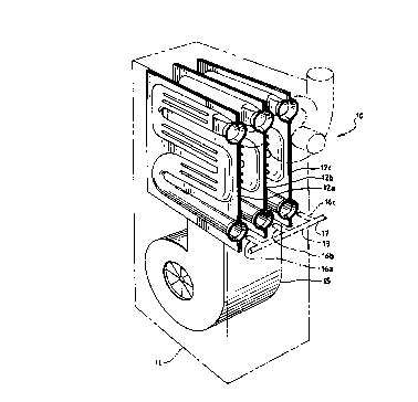
FIG. 1 is a perspective view o! the furnace of the
present invention with the housing, burner assembly and inducing
blower shown in phantom lines:
FIG. 2 is a front elevation view o! the furnace of the
present inventions
FIG. 3 is a top plan view o! the heat exchangers used
in the furnace shown in FIGS. is
- 4 -

a",_. . . .
IGr(i,7ilu i'..:
FIG. 4 is a side elevation view of the heat exchanger
used in the furnace of the present invention;
FIG. 5 is a sectional view taken along line 5-5 in FIG.
4: and
FIG. 6 is a sectional view taken along line 6-6 in FIG.
4.
While the following disclosure describes the invention
in connection with one embodiment one should understand that the
invention is not limited to this embodiment. Furthermore, one
should understand that the drawings are not to scale and that
graphic symbols, diagrammatic representations, and fragmentary
views, in part, illustrate the embodiment. In certain
instances, the disclosure may not include details which are not
necessary !or an understanding of the present invention such as
conventional details of fabrication and assembly.
DETAILED DESCRIPTION OF
Referring now to the drawings and more particularly to
FIGS. 1 and 2, one lorm of the improved gas furnace 10 generally
includes a housing 11, three heat exchangers 12a, 12b and 12c,
and a burner assembly 13 for providing hot products of
combustion to the heat exchangers. It also includes an induced
draft blower 14 for inducing the flow of combustion products
through the heat exchangers, and a circulating air blower 15 for
circulating air around the heat exchangers. The heat exchangers
12a-c lie in a compact arrangement, upright and spaced a
- 5 -

~t;9Ea3'~~:
predetermined distance apart. The circulating air blower 15
lies below the heat exchangers; and it forces ambient air in an
upwardly direction, past the heat exchangers and through an
outlet at the top of the furnace housing.
The burner assembly 13 includes three inshot burners
16a-c for the heat exchangers 12a-c, respectively. The burners
receive gas from a gas supply (not shown) through a conduit 17.
A gas pipe inlet 18 directs the supply of gas through a valve
19. Each burner extends to the corresponding heat exchanger and
directs its products of combustion into the exchanger, as
described below.
Each one of the heat exchangers 12a-c includes a first
plate member 20 and a second plate member 21 secured together in
lace-to-lace relation (See Figs. 3-6). The plate members 20 and
21 have surfaces stamped or otherwise tormed into mirror images
of each other. They have a generally rectangular peripheral
configuration with the member 20 having a length and width
greater than the length and width of the member 21. This
difterence in size allows folding and crimping of the edge
portions.o! the member 20 over the edge portions of the member
21 to secure the members together around their peripheries
(except at the inlet 22 and the outlet 23 of the heat
exchangers).
The plate members 20 and 21 of each heat exchanger
d~tine passageways which form serpentine flow paths through
whioh the hot products of combustion travel. They define an
- 6 -

2(;y~a:~':'~
inlet passageway 24 which receives a flame through the opening
22 and the combustion products the burner provides. The inlet
passageway has a J-like configuration with an elongate main
portion 24a having a generally circular configuration in
cross-section and a leg portion 24b with a cross-sectional
configuration that varies from circular to flat (with rounded
ends, See FIG. 6). One end of the leg portion 24b curves around
towards the inlet 22 and the other end is a transition from one
tube or passageway into the three connecting tubes described
below.
The plates 20 and 21 also define three sets of three
connecting tubes 25a-c, 26a-c, and 27a-c: two manifold passage-
ways 28 and 29: and an outlet passageway 31. The manifold
passageway 28 connects the first set of connecting passageways
25a-c with the second set of connecting passageways 26a-c: and
the manifold 29 connects the second set of connecting passage-
ways with the third set of connecting passageways 27a-c.
The walls of the passageways 24, 25a-c, 26a-c, 27a-c
and 31 extend across the flow of circulating air perpendicularly
of the direction of llow, increasing the surface turbulence of
the air moving over the surface of the heat exchanger and
improving heat transler. The main portion of the inlet
passageway 24 extends across the heat exchanger along one edge
of the heat exchanger. The connecting passageways 25a-c, 26a-c,
and 27a-c extend across the exchanger parallel to the main
portion o! inlet passageway 24. Each set o! connecting
- 7 -

i
passageways lies a predetermined distance from an adjacent set
or from the main portion of the inlet passageway 24. Each
passageway within each set lies a predetermined distance from an
adjacent passageway in the set. The manifold passageways 28 and
29 extend perpendicularly to the connecting passageways.
The main portion of the inlet passageway and the
connecting passageways have a circular configuration (in cross-
section): and the diameter of the passageways in one set differ
from that of another set and from the diameter of the main
portion of the inlet passageway. As shown in Fig. 5, the main
portion of the inlet passageway has an inside diameter D1: the
first set of connecting tubes have an inside diameter of D2: the
second set of connecting tubes have an inside diameter D3: and
the third set of connecting tubes have an inside diameter D4.
The diameter Di is greater than the diameter D2; D2 is greater
than D3: and D3 is greater than D4. The cross-sectional area of
the inlet passageway at any point along its length is greater
than the cross-sectional area of any of the connecting
passageways.
The passageways described above provide efficient heat
transfer through the walls of the plate members. The gradual
decrease in diameters allow the combustion products or gases to
accelerate through the heat exchanger, enhancing internal
gas-to-surlace heat transfer. The circular cross-section of the
connecting passageways also provides strength and integrity to
the exchanger structure and eliminates the need !or indents or
- g -

~~ ~,~'j~ii
embossed dimples to prevent collapse from thermal expansion.
As stated above, the heat exchangers 12a-c lie upright
and spaced apart to allow air flow around each one of them. An
outlet manifold 32 welded or otherwise secured to an edge
portion 33 of each heat exchangers receives the combustion
products from the outlet passageway 31. This outlet manifold 32
lies in the circulating airstream within the furnace 10 to
further enhance heating capacity. An inducing blower 34 draws
the combustion products from the outlet manifold to a flue duct
(not shown). The inducing blower 34 induces flow through the
heat exchangers 12a-c, moving the combustion products from the
inlet passageways 24, through the manifold, connecting and
outlet passageways, into the outlet manifold 32, and through the
flue duct. It lies below the center line of the outlet manifold
(and below the outlet passageways) to impede the migration of
flue gases during the off-cycle of the burners.
The embodiment described above includes three heat
exchangers: and each heat exchanger includes three sets of
connecting passageways. Alternatively, the furnace 10 may
include more than the three heat exchangers shown: and it may
include less than three. In addition, the heat exchangers may
include more than three sets or less than three sets of
connecting passageways. Although each set of connecting
passageways includes three passageways, it may include more than
three or less than threc passageways.
As a specific example, a gas lurnace with a compact
9 -

! ~I
construction that maximizes heat transfer was fabricated with a
heat exchanger having an inside diameter D1 of 1 3/4 inches, an
inside diameter D2 of 7/8 inch, an inside diameter D3 of 3/4
inch, and an inside diameter D4 of 5/8 inch. This heat
exchanger has a length L1 of 12 5/8 inches, a length L2 of
18 1/2 inches and a length of 15 3/4 inches for tubes 26a-c and
27a-c.
While the above description and the drawings disclose
and illustrate one embodiment, one should understand, of course,
that the invention is not limited to this embodiment. Those
skilled in the art to which the invention pertains may make
moditications and other embodiments employing the principles of
this invention, particularly upon considering the foregoing
teachings. Therefore, by the appended claims, the applicant
intends to cover any modifications and other embodiments as
incorporate those features which constitute the essential
features of this invention.
What is claimed is:
- 10 -

Representative Drawing
A single figure which represents the drawing illustrating the invention.
Administrative Status

2024-08-01:As part of the Next Generation Patents (NGP) transition, the Canadian Patents Database (CPD) now contains a more detailed Event History, which replicates the Event Log of our new back-office solution.

Please note that "Inactive:" events refers to events no longer in use in our new back-office solution.

For a clearer understanding of the status of the application/patent presented on this page, the site Disclaimer , as well as the definitions for Patent , Event History , Maintenance Fee  and Payment History  should be consulted.

Event History

Description Date
Time Limit for Reversal Expired 2008-05-20
Letter Sent 2007-05-17
Inactive: IPC from MCD 2006-03-11
Grant by Issuance 1999-08-10
Inactive: Cover page published 1999-08-09
Inactive: Final fee received 1999-04-29
Inactive: Received pages at allowance 1999-04-29
Pre-grant 1999-04-29
Letter Sent 1998-11-06
Notice of Allowance is Issued 1998-11-06
Inactive: Status info is complete as of Log entry date 1998-11-04
Inactive: Application prosecuted on TS as of Log entry date 1998-11-04
Inactive: Approved for allowance (AFA) 1998-10-16
Request for Examination Requirements Determined Compliant 1996-12-16
All Requirements for Examination Determined Compliant 1996-12-16
Application Published (Open to Public Inspection) 1994-09-05

Abandonment History

There is no abandonment history.

Maintenance Fee

The last payment was received on 1999-04-14

Note : If the full payment has not been received on or before the date indicated, a further fee may be required which may be one of the following

  • the reinstatement fee;
  • the late payment fee; or
  • additional fee to reverse deemed expiry.

Patent fees are adjusted on the 1st of January every year. The amounts above are the current amounts if received by December 31 of the current year.
Please refer to the CIPO Patent Fees web page to see all current fee amounts.

Fee History

Fee Type Anniversary Year Due Date Paid Date
MF (application, 5th anniv.) - standard 05 1998-05-19 1998-04-27
MF (application, 6th anniv.) - standard 06 1999-05-17 1999-04-14
Final fee - standard 1999-04-29
MF (patent, 7th anniv.) - standard 2000-05-17 2000-04-05
MF (patent, 8th anniv.) - standard 2001-05-17 2001-03-19
MF (patent, 9th anniv.) - standard 2002-05-17 2002-03-28
MF (patent, 10th anniv.) - standard 2003-05-19 2003-03-24
MF (patent, 11th anniv.) - standard 2004-05-17 2004-03-19
MF (patent, 12th anniv.) - standard 2005-05-17 2005-03-18
MF (patent, 13th anniv.) - standard 2006-05-17 2006-03-21
Owners on Record

Note: Records showing the ownership history in alphabetical order.

Current Owners on Record
EVCON INDUSTRIES, INC.
Past Owners on Record
ALAN ZIMMERMAN
THOMAS CHASE
Past Owners that do not appear in the "Owners on Record" listing will appear in other documentation within the application.
Documents

To view selected files, please enter reCAPTCHA code :


To view images, click a link in the Document Description column. To download the documents, select one or more checkboxes in the first column and then click the "Download Selected in PDF format (Zip Archive)" or the "Download Selected as Single PDF" button.

List of published and non-published patent-specific documents on the CPD .

If you have any difficulty accessing content, you can call the Client Service Centre at 1-866-997-1936 or send them an e-mail at CIPO Client Service Centre.


Document
Description 
Date
(yyyy-mm-dd) 
Number of pages   Size of Image (KB) 
Claims 1998-09-15 4 176
Abstract 1995-06-09 1 31
Claims 1995-06-09 5 199
Drawings 1995-06-09 2 84
Description 1995-06-09 10 413
Drawings 1999-04-28 3 109
Representative drawing 1999-08-01 1 15
Commissioner's Notice - Application Found Allowable 1998-11-05 1 163
Maintenance Fee Notice 2007-06-27 1 173
Correspondence 1999-04-28 4 138
Fees 1997-05-11 1 143
Fees 1996-03-25 1 74
Fees 1995-03-26 1 57
Courtesy - Office Letter 1993-10-21 1 19
Examiner Requisition 1998-03-26 1 38
Prosecution correspondence 1996-12-15 1 32
Prosecution correspondence 1998-06-14 2 67