Note: Descriptions are shown in the official language in which they were submitted.
WO 92/08380 PCT/CA91/00413
- 1 - ~~~~~~~;
PROTECTIVE HEADGEAR AND
DETACHABLE FACE PROTECTOR
TECHNICAL FIELD
The present invention relates to a protective
sports headgear which comprises a helmet member
having a sizing harness secured in the helmet and
adjustable to fit the wearer's head by means of
finger adjusting members secured to the helmet and
accessible from the outer face of the helmet.
BACKGROUND ART
Protective headgears are worn in various types
of sports such as hockeyr football, cycling, just to
name a few, and these have various shapes and forms
and are provided with or without~face protecting
devices. Such known helmets have various disadvan-
tages which have heretofore not been remedied. One
of the disadvantages is that certain of these helmets
do not provide adequate protection to the head of the
wearer and one cause of this is usually because the
helmet is not properly fitted to the head of the
wearer. Another disadvantage of known helmets is
that when they are snugly fit on the head of a
wearer, they do not provide head ventilation and.
accordingly, the wearer will sweat profoundly from
the head often impairing his vision as well as making
the wearer feel very uncomfortable. This is particu-
larly so when the helmet is fit with a protection
visor. The sweat will fog the visor and thereby
impair the wearer's vision which could again be a
cause of injury due to poor visibility. Another
disadvantage of known helmets is that in certain
S~~ST~TI~TE SHEET
WO 92/08380 PCT/CA9i/00413
_ 2 _
sports, they are provided with faceguards which are
attached by metal rivets or other type fasteners and
such fasteners can cause injury to the wearer,
particularly when they protrude inside the helmet.
Referring now more specifically to helmets
utilized in the sport of hockey, it has become common
practice to provide visors and faceguard frames
secured to the helmet whereby to protect the eyes and
nose of the wearer or the entire face of the wearer
including the ears. The majority of known visors
often need to be cleaned when they fog up due to
sweat generated by the wearer, it is often necessary
to remove the entire helmet and to hinge the
faceguard in order to have access to the inside
surface of the visor. This is time-consuming and
often the hockey player will continue playing the
game with impaired vision thereby diminishing his
abilities as well ,as making him more susceptible to
injury.
DISCLOSURE OF INVENTION
It is a feature of the present invention to
provide a protective sports headgear which substan
tially overcomes all of the above-mentioned disadvan
tages of the prior art.
Another feature of the present invention is to
provide a protective sports headgear having a helmet
member with a sizing harness secured inwardly thereof
with adjustable bands which can be adjusted with the
helmet positioned on the wearer's head by adjustable
members provided on the outer surface of the helmet.
Another feature of the present invention is to
provide a protective sports headgear which comprises
a helmet having a sizing harness secured inwardly
thereof to space the wearer's head from an inner
protective lining in at least some inner areas of the
helmet member and wherein vent holes are provided in
WO 92/08380 ~ ~ ~ ~ ~ ~q ~ PCT/CA91 /00413
- 3 -
the helmet to ventilate the wearer's head to reduce
sweating and to make the helmet more comfortable.
The sizing harness will accommodate any head size due
to its flexibility in adjustment.
Another feature of the present invention is to
provide a protective sports headgear having a
faceguard frame and a visor hingedly secured to the
frame whereby the visor can be easily hinged away
from a sighting opening so as to clean the visor or
to simply place it in a position of non-use when the
wearer does not require same.
. _ . . . Another feature of the present invention .is.-to
provide an improved protective sports headgear having
plastic-type fasteners secured thereto to retain
various parts of the helmet construetion and wherein
the fasteners provide added protection o the wearer
and wherein the construction and design o~f the helmet
is an improvement over known helmets of the prior
art.
According to the above features, from a broad
aspect. the present invention provides a protective
headgear which comprises a helmet member shaped to
protect the top, rear, front and sides of a wearer's
head. The. helmet member has a rigid outer shell with
an inner protective lining of shock absorbing
material., A izing~harness is secured to the helmet
and disposed inwardly thereof. The harness has a
height adjusting band and a horizontal contour
adjusting band. Adjustable sizing means is secured
to the helmet and the adjusting bands to fit the
bands on the head of a wearer and thereby spacing the
head from the protective lining in at least some
inner areas of the helmet member. Means is provided
to secure the helmet to a wearer's head.
WO 92/08380 PCT/CA91 /00413
20~6~41 _.
- 4 -
Another feature of the present invention is to
provide an improved protective sports headgear for
use in the sport of hockey and wherein an ear shield
is secured to the helmet member and extends over an
ear clearance area whereby to cover a substantial
portion of a wearer°s ear.
Another feature of the present invention is to
provide an improved protective sports headgear having
a helmet member comprised of a rigid outer shell and
an inner protective lining of shock absorbing
material secured to the shell .by ribbed fasteners
_. ..._ ._ _. .constructed of plastics material . and .which do. not
transfer impact.
Another feature of the present invention is to
provide a faceguard frame securable to a helmet
member to protect a wearer's face and wherein the
faceguard frame is of mesh-like construction and has
a sighting opening in an eye and nose region of the
face of the wearer. A visor of clear plastics
material is hingedly connected to the faceguard frame
and hingeable upwardly of the sighting opening. Lock
means is provided to immovably secure the visor in
its position of use across the sighting opening. A
half faceguard frame is also provided.
Another feature of the present invention is to
provide a thermoformed plastic frame secured to a
helmet member of a protective sports headgear to
protect a goaltender's face. The thermoformed
plastic frame has a face opening across which is
secured a protective member. A pivoting throat guard
is formed as a solid molded piece and secured to the
frame by opposed pivot connectors and pivotal from a
lower chin band section of the frame.
WO 92/08380 2 ~ ~ ~j j ~ ~ PCT/CA91/00413
- 5 -
BRIEF DESCRIPTION OF DRAWINGS
A preferred embodiment of the present invention
will now be described with reference to the
accompanying drawings in which:
FIGURE 1 is a side view of the protective
sports headgear of the present invention;
FIGURE 2 is an inside view of the protective
sports headgear of Figure 1;
FIGURE 3 is a perspective inside view
illustrating the positioning of the head sizing
harness;
FIGURE 4 is a plan view illustrating the shape
and construction of the sizing harness
FIGURE 5 is a fragmented perspective view
showing the manner in which the sizing harness is
secured to an adjustment member accessible from the
outer surface of the helmet;
FIGURES 6A, 6B and 6C are plan, side and end
views, respectively, of the sizing band connectors;
FIGURES 7A, 7B and 7C are plan, side and end
views, respectively, showing how the sizing band
connector is secured to the housing in which an
adjustment knob is retained;
FIGURES 8A and 8B are side and end views,
respectively. of the adjustment knob;
FIGURES 9A and 9B are side and top views,
respectively, of the trough-like housing;
FIGURES 10A and lOB are side and top views,
respectively, of rib fasteners and stem-engaging cup
member as seen from the end edge thereof;
FIGURES 11A and 11B are similar views to
Figures 10A and lOB but showing the rib fastener from
the side thereof;
FIGURE 12 is a section view of a female lug
fastener constructed of plastics material;
FIGURE 13 is a side view of a male snap
fastener;
WO 92/08380 PCT/CA91/00413
2fl96~41
- 6 -
FIGURES 14A, 14B and 14C are side, section and
plan views of a frame attachment hinge member
constructed of plastics material
FIGURE 15 is a side view of a faceguard frame
constructed in accordance with the present invention;
FIGURE 16 is a fragmented front view of the
faceguard frame of Figure 1;
FIGURE 17 is a top inside view of the rib cage
section of the faceguard frame;
FIGURES 18A and 18B along section lines A-A and
B of Figure 16;
FIGURE 19A is a side view showing the hinge
connection and detachable lock means of the faceguard
frame;
FIGURE 19B is a section side view of the
flexible retention finger of Figure~l9A;
FIGURE 20 is a side view, partly ,sectioned,
showing the construction of the visor and its attach-
ment means to secure to the faceguard frame;
FIGURE 21 is a front view of a visor;
FIGURE 22 is a top view of the visor;
FIGURE 23 is a fragmented section view of the
retention bore which engages with the retention head
of the flexible retention finger;
FIGURES 24 and 25 are side views showing the
manner in which the visor is hinged to the faceguard
frame;
FIGURE 26 is a view similar to Figures 24 and
25 but showing the visor secured to a half faceguard;
and
FIGURE 27 is a perspective view of a thermo-
formed plastic goalie faceguard frame for securement
to a helmet member.
WD 92/08380 ~ , PCT/CA91100413
_ 7
MODES FOR CARRYING OUT THE INVENTION
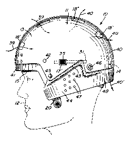
Referring now to the drawings, and - more
particularly to Figures 1 to 3, there is shown
generally at 10, the protective sports headgear of
the present invention and particularly, but not
exclusively, a sports headgear. The headgear
comprises a helmet member 11 which is shaped to
protect the top. rear, front and sides of a wearer's
head 12. The helmet member has a rigid outer shell
13 with an inner protective lining 14 formed of thick
polyurethane foam or other rigid foam-like material
__ being light, weight and having shock_.___absorbing
properties. The shell has a uniform outer surface
with no ridges to catch when the wearer's head hits
objects. The uniform surface also deflects blows
imparted to it.
A sizing harness 15 is secured to the helmet by
fasteners 16, which will be described later, at
various predetermined locations along the band, so as
to secure same to the helmet member while still
providing adjustability about the wearer's head. As
shown in Figure 4, the sizing harness 1~5 is made as a
one-piece band of flexible material. herein a
flexible plastics material, and defines a horizontal
'25 contour-adjusting band section I5' and a height-
adjusting band section 15".
Adjustable sizing means, herein in the form of
adjustment knobs 17, are provided on each side of the
~e~:met,and accessible from the outer face of the
rigid outer shell 13. The knob 17' as shown in
Figure 1 is utilized to adjust the horizontal contour
band section 15' wh~.le the adjustment knob 17, as
shown in Figure 3, is utilized to adjust the height-
adjusting band section 15". Accordingly, the bands
can be fitted comfortably about the wearer's head and
by such means can space the wearer's head in at least
some section of the helmet member to provide a
WO 92/08380 PCT/CA91/00413
~,~9~a~1 _.
_8_
comfortable fit and also to permit ventilation
through the helmet through the vent holes 18' and 18"
extending through the outer shell 13 and the inner
protective lining 14. Also, when an impact is
absorbed by the helmet, it is easy to readjust the
harness if it loosens during impact as the blow is
absorbed.
Referring again to Figure 4, it can be seen
that certain parts of the band are provided with
holes 18 which reduces the formation of sweat against
the wearer's head. Lugs 19 are also formed integral
-- --- - - with the band to provide securement- of -same to the
helmet member. Chin strap connecting bands 20 are
also formed integral with the harness. Also formed
integral with the adjustment horizontal and height
adjustment band sections 15' and 1S" is a connector
bridge 21 having an elevated top wall 24 as shown at
2.2. A pair of connecting holes 23 are provided in
the top wall 24 of the connector bridge 21 whereby to
connect to adjustment members 25 as shown in Figure
5.
Referring now additionally to Figures 5 to 9B,
there will be described the manner in which the
harness is adjustable. As shown in Figures 6A to 6C,
the adjustment members comprise a band connector 26
provided with an attachment element 27 securable to a
respective one of the adjusting band sections 15' and
15". An elongated flexible threaded member 28 is
integrally formed with the attachment element 27.
One or more prangs 29 are formed in the attachment
element 27 and protrude thereabove to engage within
the connecting holes 23 provided in the connector
block 21 of the harness. The securement of the
attachment element 27 to the connector block could
also be made by other fastening means, such as a
separate connector pin.
WO 92/08380 ~ pCT/CA9l/00413
_ g _
A flat wing element 30 is formed integral with
the attachment element 27 and is retained captive
between an inner face of the outer shell 13 and the
protective lining 14 and extends to each side of a
S guide channel 31, as shown in Figure 5. The guide
channels are formed within the inner protective
lining 14 and extend therethrough. The location of
the horizontal guide channel 31 is shown in phantom
lines in Figure 1 and the vertical guide channel 31'
is shown in phantom lines in Figure 3. The size of
this channel is selected so that the connector bridge
31 is.closely guided therein so as to- maintain the
adjustable band sections in proper position inside
the helmet.
Figures 8A and 8B illustrate the construction
of the adjusting knobs 17 and as herein shown, they
are comprised as a cylindrical wheel 32. having an
inner threaded bore 33 and a plurality of finger
engaging ribs 34 formed in an outer surface thereof
and extending parallel to the through bore 33 for
rotating the cylinder knob 32 about the elongated
threaded member 28, as shown in Figure 7C.
Referring additionally to Figures 9A and 9B,
there is shown the construction of a trough-like
. housing 35 which is secured in locating holes
provided in the outer shell 13 and inner protective
lining 14. The trough-like housing 35 has an arcuate
side wall 36 and opposed U=shaped end walls 37.
Holes 38 are provided in the end walls to accommodate .
the passage of the elongated flexible threaded member
28 therethrough, as shown in Figures 7A to 7C. The
adjusting cylinder knob 32 is located within the
housing 35 and is in threaded engagement with the
threaded member 28 extending therethrough, as shown
in,Figure 7C. Accordingly, by turning the knob 32,
the threaded member 28 is displaced axially through
the housing and thereby displaces the adjusting band
WO 92/08380 M PCTlCA91/OOA13
20~~~~~.
- to -
sections 15' and 15" whieh are connected to the
attachment element 27. Figure 7C shows the position
of the adjustable band section 15' riding on the top
inner surface of the inner protective lining 14 with
the wing element 30 being positioned in sliding fit
between the outer shell 13 of the helmet and the
protective lining 14 and extending beyond the edges
of the guide channel 31. Accordingly, by rotating
the adjusting knobs 17 and 17', the band is fitted
about the wearer's head and this can be done while
the helmet is positioned on the wearer's head. The
.. , adjustment knobs _17 also provide for very.._finite....-
adjustment of the band and thus adding to the comfort
and proper sizing. It is also not necessary to remove
the helmet to make the sizing adjustment. It is also
pointed. out that the cylinder knobs are disposed
along different axes to indicate .to which of the
bands it is connected and as hereinshown, the adjust-
ment knob of Figure 1 is disposed horizontally to
indicate it is attached to the horizontal band
section 15' whilst the adjustment knob 17 is, disposed
vertically to indicate that it is connected to the
vertical or height adjustment band section 15".
Referring to Figure l, it can be seen that a
plurality of vent holes 18 are provided within the
outer shell and the inner protective lining with the
front vent holes 18' being disposed horizontally to
admit more air inside the helmet member 11.
Accordingly, as the wearer displaces himself, air
enters the helmet through the frontal air holes in
the direction of arrows 39 and exit through the top '
holes 18" as shown by arrows 40. Some ventilation
also takes place through the back of the neck as '
illustrated by arrow 40' due to the spacing provided
by the harness. This permits the wearer's head to be
cooled thereby generating less sweat and maintaining
the-wearer more comfortable to perform his sports
WO 92/08380 ~ ~ PCT/CA91 /00413
- 11 -
activity. The height adjusting band' maintains a
clearance between the inner surface of the inner
protective lining 14 and the top of the wearer's head
to achieve this feature. Of course, this clearance
will vary depending on the size of the wearer's head
and the size of the helmet being worn. The vent
holes 18 are herein shown as disposed along a central
band portion of the helmet from a frontal head area
to a rear head area. Although these are shown as
being of substantially rectangular configuration,
they could also be shaped differently and disposed in
spaced-apart pairs or again differently. Channels___
(not shown? could also be formed inside the. lining
and disposed in alignment with the vent holes.
Referring again to Figures 1 to 3, it can be
seen that the inner foam protective lining 14 extends
beyond at least the forehead and neck portion of the
rigid outer shell. A protective shield 41 formed of
flexible plastics material extends over a portion of
the rigid foam material l4 in the forehead portion of
the headgear to protect the foam in this area. This
shield is immovably secured in position by means of
plastic fasteners 42.
As can be seen from Figure l, the helmet member
defines an ear clearance area 43 on each side
thereof. . An ear shield 44 is secured to the helmet
by suitable fasteners such as at 45 and 46 and
extends over the ear clearance area and depends
therefrom to cover a substantial portion of a
wearer's ear. The ear shield 44 is molded from a
flexible plastics material and protrudes outwardly of
the plane of the rigid outer shell. Vent holes 47
are provided in the shield to vent this area and also
not to shield the ear from sounds so that the
wearer's audibility is not impaired. This ear shield
is molded as a U-shapeii member with an ear shield
section 44 at opposed ends of the member and a
WO 92/08380 PCT/CA91/00413
~Q96~41
- 12 -
connecting band section 48 being disposed
intermediate of the ear shields and overlying a rear
extension portion of the inner protective lining 14
in a rear portion of the helmet. This provides added
protection for the inner protective lining in this
area of the wearer's head. Accordingly, this
construction provides added protection to the
wearer's head in the ear and neck portion areas.
Referring now to Figures 10A, 10B, 11A and 11B,
there is shown the construction of rib fasteners 50
which are constructed of plastics or nylon-type
.._......_material. The rib fasteners are provided.with a rib
stem member S1 and a stem-engaging cup member 52.
The stem member S1 is an elongated straight flat stem
member, as shown in Figure 11A, and is provided with
opposed transverse, equidistantly spaced attachment
ribs 'S2 on opposed flat side walls 53 of the stem. A
flat transverse head 54 is provided at one end of the
stem. A tapered locating free end 55 is provided at
the opposed end of the stem. The cup member 52 has a
recessed bottom wall 56 with a straight rectangular
slot 57 provided centrally therein for receiving the
free end and a portion of the ribbed stem member
therethrough. A circumferential flange 58 extends
about the side wall 59 of the cup member which is
herein shown as a circular can member. x, nair of
retention flexible shoulders 60 are disposed on
opposed sides of a rectangular slot 57 and have an
inward inclination to engage with the stem between
30' the ribs, as shown in Figure 10A.
The ribs 51 are provided with outwardly sloping
side walls 51' and a transverse retention rear wall
51°'. The flexible shoulders 60 of the cup member are
displaced outwardly by the sloping side wall 51' when
the stem is pushed through the rectangular slot 57.
Each of the flexible shoulders 60 have a flat
engaging top edge 61. This top edge 61 engages with
WO 92/08380 2 O g 6 ~ ~ ~ PCT/CA9i/OOal3
- 13 -
the transverse retention rear wall 51" of the ribs to
prevent the stem from being pulled back from the
rectangular slot of the stem engaging cup. It is
also pointed out that the side walls 59 of the cup
member are longer than the distance from the. leading
edge of a rib sloping side wall 51' disposed on top
of the pair of retention shoulders 60 so that the
stem can be severed at the rib leading edge so that
the severed stem does not protrude beyond the circum-
ferential flange 58 of the cup. This provides added
security inside the lining of the headgear not to
touch the wearer's head. The stem and cup members
are molded from pliable plastic material. As shown
in Figure 10A, the cup member 52 is disposed in 'a
circular bore 62 formed in the inner surface of the
protective material 14. The head 54 of the stem
rests on an outer surface of the rigid outer shell
13.
Figure 12 shows the construction of a female-
type lug fastener 63 which is utilized to secure
various parts to the helmet member. The female lug
fastener is constructed from a plastics material and
provided with an inner flexible rim 64 which flexes
outwardly to allow the passage of a male snap
fastener 65 therein. The male snap fastener is
provided with a retention head 66 and a flat outer
head 67. These fasteners are all constructed of
plastics material to provide added security to the
wearer and are preferable over metal fasteners.
Referring now to Figures 14 to 18, there is
shown the construction of a one-piece molded clear
plastic faceguard frame 70 ,constructed in accordance
with the present invention. The faceguard frame is
of mesh-like construction and is comprised of a
ribbed cage section 71 disposed below the eye and
nose region 72 of a wearer's face whereby to protect
the mouth, chin, neck and lower face of the wearer.
WO 92/08380 PCT/CA91/00413
2096~~1
- 14 -
A forehead section 73 is disposed in line with the
forehead of a wearer and is provided for hinge
attachment with the helmet member 11. A large
sighting area 74 is defined between the forehead
section 73 and the ribbed cage section 71.
The ribbed cage section 71 is constructed of a
plurality of horizontal and transverse ribs 75 and 76
respectively, as can be seen from Figures 18A and 18B
and which are spaced apart a predetermined distance
to provide adequate protection. The ribs are also of
substantially triangular .cross-section, as shown in
Figures 18A and-18B, with the apex 77 of these-ribs-
being located exteriorly of the cage section and
aligned with the cone of vision of the sighting
opening not to impair the wearer's vision. The
forehead section 73 is provided with a rear rib 78
rearwardly of a top edge thereof. This rib is
received within an integrally formed frame attachment
hinge member 79 as shown in Figures 14A to 14C.
As shown in Figures 14A to 14C, the frame
attachment hinge member is an integrally formed
member of flexible plastics material and defines a
female connector section 80 for receiving a male snap
member, such as the member 65 shown in Figure 13,
whereby to secure the frame attachment member 79 to
the helmet member. Retention loop section 81 is
formed integral with the female connector and is
positioned about the rib member 78 on the forehead
section of the faceguard frame 70. The retention
loop 81 has a flexible throat opening 82 disposed
rearwardly thereof and extends about the female
connector 80 to lock the opening 82 when the male
snap member 65 is engaged with the female connector
80. In this manner; the faceguard frame is hingedly
retained by the frame attachment member to the front
WO 92/08380 PCT/CA91 /00413
209~~4~.
- 15 -
forehead portion of the helmet member. Preferably,
two of such frame attachment hinge members are
provided one on each side of the central rib 83
provided in the forehead rib section 73.
The faceguard frame 70 is also provided with
integrally formed opposed rear wall sections 84
disposed behind the cone of vision of the headgear
and a slot 85 is formed in a bottom corner thereof
through which an attachment strap is secured to
connect the faceguard frame 70 to opposed sides of
the helmet member, in a manner well known in the art.
.A visor hinge connecting hole 86 is provided in _.an _. _ . _ ._
upper area of the rear wall sections 84, whereby to
receive a visor hinge member, as will be described
later. A lock retention finger 87 is also formed
integral with the rear wall section 84 and its
function will also be described later.
Referring now additionally to Figures 19A to
26, and more particularly to Figures 24 to 26, it can
be seen that a clear plastics visor 88 is hingedly
connected on the hinge pin fastener 89 to the
faceguard frame 70 whereby to overlie the sighting
opening 74 to protect the eye and nose region of the
face of a wearer. As shown in Figures 20 to 23, the
visor 88 is provided with an elongated slot 90 formed
on opposed side end portions thereof for connection
with the pivot connector 89. The slot 90 has a top
vertical section 91 to permit the visor to be
displaced vertically far nesting and removal from
locating ledges 92 formed along the top edge of the
ribbed cage section 71 below the sighting opening 74.
The. slot 90 further defines a rearwardly extending
depending section 93 to permit the visor to hinge
upwardly and outwards as shown in Figures 25 and 26.
respectively. A retention bore 94 is disposed below
the slot 90 and has a straight bottom sloping edge
95. as better seen in Figure 23, for mating retention
WO 92/08380
PCT/CA91 /00413 '
- 16 -
with an undercut edge 96 of the lock retention finger
87. as better shown in Figure 19B. As shown in
Figure 19A, the lock retention finger is integrally
molded with the faceguard frame which is constructed
of a clear plastics material. The head section 97 of
the retention finger 87 is provided with an outwardly
protruding wall 98 so that the retention ledge 96
extends outwardly of the outer face of the rear wall
section 84 of the faceguard frame 70. The hinge
connection 89 maintains the retention bore 94 of the
visor perfectly aligned with the head 97 of the lock
retention finger 87 so that the head sloping wall 98
will~cause the finger 87 to flex slightly inwardly of
the faceguard frame when hinged thereover and as soon
as the retention bore 94 is aligned with the head 97,
it will snap or click into position locking the visor
to the faceguard frame with the lower edge ,99 of the
visor resting on the support ledges 92. The clicking
sound assures the wearer that the visor is locked in
position.
The visor 88 is also provided with a locating
flange 100 in a top edge thereof to guidingly
position the visor relative to the vertical ribs 83
and 101 provided in the forehead section 73 of the
faceguard frame 70. Slots 102 are defined between
flange sections 100' to accommodate the ribs 83 and
101. Accordingly, the locating flange 100 also sits
on the horizontal frontal rib 103 of the forehead
section 73.
As can be seen in Figures 24 to 26, in order to
hinge the visor 88 upwardly of the sighting opening
74, it is firstly necessary to depress the head 97 of
the lock retention finger 87 to disengage the ledge
96 from the ledge 95. The visor can then be pushed
upwardly off its nesting ledges, as shown in Figure
25. The hinge pin 89 has thus moved to the bottom of
the vertical. section 91 of the visor connecting slot
WO 92/08380 ~ ~ PCT/CA91/00413
- 1. -
93. The visor is then pushed outwardly and upwards,
as shown in Figure 26, and the hinge pin 89 is then
located in the bottom portion of the rearwardly
depending slot section 93. In this position, the
wearer has clear vision and this permits the visor to
clear itself by ventilation of the fogged up area.
It also permits better ventilation of a wearer's face
permitting the wearer to wipe his forehead or eyes.
The hinge pin 89 may be formed from the connector
described in Figures 12 and 13 or otherwise and
provide a rigid frictional retention fit so as to
maintain. the visor in its retracted position as shown
in Figure 26. Alternatively, it is conceivable that
the bottom portion of the slot section 93 be provided
with an upper end section 93' (see Fig. 24) in which
the hinge pin 89 would enter to maintain the visor
supported as shown in Figure 26.
As is shown in Figure 26, the faceguard frame
70' is herein shown as a half-frame to support the
visor 88 only. The fastener 89 in this application
goes into the helmet as well as through the frame 70'
and the visor 88. With this frame, the eyes and nose
area of the face only is protected.
Referring now to Figure 27, there is shown a
thermoformed plastic frame 110 secured to the helmet
member 11 whereby to protect a goaltender's face.
The plastic frame 110 has a face opening 111 across
which is secured a protective grill member 112, well
known in the art, and which is usually formed from
steel wires welded together. The plastic frame 110
of the present invention is pivotally secured to the
helmet member 11 by the pivot fastener 113 whereby
the frame 110 can be displaced rearwardly along the
direction of arrows 114 to clear the face of the
wearer. A pivoting throat guard 115 is pivotally
WO 92/08380 PCT/CA91/00413
~o~s~4~
- 18 -
secured by connector 116 to the thermoformed plastic
frame 110 and pivots downwardly from the lower chin
band section 117 of the frame 110 in the direction as
shown by double arrowhead 118.
The throat guard 115 has an integrally formed
bib section 119 which extends outwardly of an
upwardly extending ledge section 120 which mates or
which is closely spaced to the chin band 117 whereby
the chin band will restrict the upward displacement
of the throat guard 115 so that it does not pivot
above the chin band.
-. The.thermoformed plastic frame 110 is provided-----
with an integrally formed rearwardly sloping forehead
section 121 which overlies the frontal portion of the
helmet member 114 and outwardly flared side wings 122
which protects and overlaps the ears of a wearer. A
plurality of holes 123 are provided in the side wings
for ventilation and not to impair the audibility of
the wearer.
It is within the ambit of the present invention
to cover any obvious modifications of the invent~.on
described herein provided such modifications fall
within the scope of the appended claims.
30