Note: Descriptions are shown in the official language in which they were submitted.
20966~S
~092/09394 PCT/AU9l/00~00
IMPROVEMENTS IN OR RELATING TO SLOTTING MACHINES
The invention relates to a widely used component of
an automotive power steering valve known as the sleeve,
which has arranged inside the bore a plurality of parallel
longitudinally extending, circumferentially spaced ports
in the form of slots. These slots are blind-ended thus
forming a series of closed chambers within the bore of the
sleeve which operate in conjunction with similar
circumferentially spaced ports in a co-acting cylindrical
valve rotor component housed within the sleeve upon slight
relative rotation between these components.
Such sleeves are frequently manufactured by broaching
the bore of a turned blank so as to form a series of slots
therein. Subsequently each end of the sleeve is
counterbored for a short distance and close-fitting stop
rings are inserted to form a closed chamber within the
sleeve. Alternatively after broaching the turned blank,
the ends are closed by cold-forming the material of the
sleeves each end, and the excess deformed material is
later removed by remachining the bore.
Still another, but less widely used, construction
calls for each of the slots to be scooped out of the bore
of a turned blank by a finger-like tool supported in a
spindle for angular reciprocation, the tool havinq a
cutting edge which executes a series of progressively
deeper cutting strokes so forming a blind-ended slot which
is arcuate in longitudinal section. This process is
repeated for all of the required slots, usually 4, 6 or 8
slots for most automotive applications. A specialised
machine capable of performing this operation was first
disclosed in US Patent 3,765,305. As can be seen from
Figs. 13 and 14 of that specification, the depth of
material removed during one cutting stroke of this machine
is approximately constant during the duration of each
cutting stroke, leading in turn to a uniform chip
thickr.ess and therefore an optimum cutting geometry.
2096645
W O 92/09394 PC~r/A U91/00500
- 2 -
However, at the completion of the slotting operation, the
machine is necessarily stopped and the work holding chuck
is swivelled sideways to allow unloading and loading of
the next sleeve blank. To enable this to occur the locus
of the tool tip during each cutting stroke is required to
extend axially clear of the bore. This overstroking
requirement increased the inertial imbalance of the
machine and hence slowed its operation to such a degree
that the design was abandoned.
In US patent 4,154,145 a more refined design of
slotting machine is disclosed capable of overcoming the
aforementioned limitations. Machines of this design have
been used for several years however, as described in that
specification, loading and unloading of the work holding
lS chuck requires the mechanism to be stopped in a very
precise position. In order to accomplish this, an
electric brake and separate electric motor is provided to
move the mechanism slowly to the required precise
position. A stop 41, as shown in Fig. 2 of that
specification, is then removed and a bell crank mechanism
is folded by the action of an air cylinder (not shown) in
order to swing the tool holder clear of the workpiece. In
order to accomplish this motion without the tool holder
interfering with the top of the sleeve bore diametrically
opposite to the slot being cut, the line joining the
centre 8 of the cutting spindle 7 and the centre 10 of the
cutting spindle carrier 9 will generally need to be even
more nearly horizontally disposed than shown in Fig. 2,
whereas, desirably this line should be vertical, as in the
case of the slotting machine disclosed in US Patent
3, 765,305. This enforced compromise results in the depth
of material removed during each cutting stroke being up to
three times greater at the end of the stroke compared with
the start of the stroke, whereas, desirably, this depth of
cut should be uniform. The resulting chip is therefore
209664~
~0g2/09394 PCT/AU91/00500
- 3 -
relatively thin as the cutting tool enters material in the
sleeve bore and thicker as it exits the material. Such a
cutting geometry is well recognised as suboptimal in other
areas of metal machining. For example in the case of
milling machines, "climb milling" is frequently employed
to avoid the progressively thicker chip formed by each
tooth of the milling cutter during "conventional" milling.
Wider adoption of that slotting machine has been
further hindered by the concern of potential users of the
process over the use of a single cutting edge to machine
all the slots in the sleeve as compared to the several
hundred cutting edges of the broach in the conventionally-
used broaching method. This limitation is further
exacerbated by the need to employ a finger-like cutting
tool of a shape dictated by the need to swing the tool
clear of the bore for loading and unloading of the work
holding chuck. This demanded the use of a cutting tool
having a tungsten carbide tip brazed to its shank, or in
the case of larger diameter sleeves, a single cutting edge
special tungsten carbide tip of the throw-away type was
used. Neither arrangement is satisfactory, particularly
for machining small-bore-diameter sleeves which are
increasingly coming into use.
Now the standard tungsten carbide throw-away tips
available in the industry used for machining grooves are
generally of an equilateral triangular form providing
three cutting edges and conforming to internationally
accepted dimensional standards. Such tools are available
in many grades of tungsten carbide and ceramic material,
frequently Titanium Nitride (TiN) coated, and their use
will make possible the employment of the slotting process
for large volume sleeve production. However such standard
tips, of a width corresponding to a typical sleeve slot
width for a given bore diameter, are excessively large in
size compared with such a bore diameter and therefore
-
20961~4S
W092/09394 PCT/AU91/00500
cannot be accommodated in a tool holder of the type
disclosed in US Patent 4,154,145. This is because of the
aforesaid limitation imposed by the need to retract the
tool holder in an arcuate manner during unloading and
loading operations.
According to the present invention the work holding
chuck is contained in a work holding spindle and, at the
moment when the tool is radially clear of the sleeve bore,
the work holding spindle slides along its axis a
sufficient distance to allow the sleeve to be removed from
the work holding chuck without any interference with the
tool holder. Consequently, the reciprocation of the tool
may continue during the load/unload cycle and only
infeeding of the tool and indexing of the work holding
lS spindle need be momentarily arrested. Since, in a
relative sense, the tool holder now retracts axially
relative to the workpiece rather than arcuately as in the
case of the slotting machine disclosed in US Patent
4,154,145, a tool holder geometry compatible with standard
tungsten carbide throw-away tips can now be employed to
machine even small bore sleeves, greatly reducing the
operating cost of such machines for large volume sleeve
production. The absence of the need for arcuate
retraction of the tool holder also permits the
aforementioned optimum cutting geometry to be achieved, in
which the depth of material removed during one cutting
stroke of this machine is approximately constant
throughout the duration of each cutting stroke.
The present invention consists in a machine for
machining blind-ended slots longitudinally disposed within
the bore of a sleeve, comprising a work holding spindle
indexable about a rotational axis, said spindle
incorporating a work holding chuck for holding said
sleeve, a cutting tool mounted on a cutting spindle, the
axis of said cutting spindle being offset from and at
20966~5
~092/09394 PCT/AU91/00500
right angles to the rotational axis of said work holding
spindle, means of supporting said cutting spindle for
angular reciprocation, infeed means to permit said cutting
tool to execute a succession of progressively deeper
cutting and subsequent return strokes in relation to said
bore of said sleeve, whereby after a series of indexations
of said work holding spindle, said blind-ended slots are
machined in a sleeve characterised in the provision of
means slideably supporting said work holding spindle for
movement along an axis parallel to said rotational axis of
said work holding spindle and, means acting to disable
said infeed means after said machining of all said slots
is completed, and means to slide said work holding spindle
axially relative to said cutting spindle a distance such
that said cutting tool is radially and axially clear of
said bore.
It is preferred that, after the cutting tool is
radially and axially clear of the bore, additional
relative movement between the work holding spindle and the
cutting spindle enables axial extraction of the sleeve out
of the work holding chuck without interference with the
still-reciprocating cutting tool. ~he sleeve can then be
transported laterally to a loading station and hence to a
conveyor belt etc.
It is also preferred that the axial slideability of
the work holding spindle is achieved by journalling this
work holding spindle for rotation within a sliding work
spindle carrier which, in turn, is able to slide axially
with respect to the machine frame. It is also possible,
however, that rotation and axial slideability of the work
holding spindle could be achieved by directly
plain-journalling this element in the machine frame. A
linear ball race could also be employed to achieve these
two motions.
The sliding work spindle carrier in this embodiment
W092/09394 2 0 9 6 6 4 ~ PCT/AU91/00500
is driven up into the cutting position and down into the
loading position by a rise and fall cam mechanism. It is
preferred that in the upper cutting position, a conical
surface on the exterior of the sliding spindle carrier
forcibly engages a corresponding conical socket in the
machine base providing rigid and accurate concentric
location of the work holding spindle during the cutting
cycle throughout the life of the machine.
Desirably, a loading mechanism is arranged to be
driven up and down with the sliding work spindle carrier
along an axis parallel to that of the sliding work spindle
carrier but offset therefrom and is equipped with a pair
of grippers which hold the sleeve on the short section of
its outside diameter which protrudes from the work holding
chuck. In a preferred arrangement, as the sliding work
spindle carrier commences to descend, the work holding
chuck therein is relaxed and shortly thereafter the
loading mechanism is arrested while the sliding work
spindle carrier continues to descend. By this means the
sleeve is extracted from the work holding chuck, yet clear
of the lower excursion of the reciprocating tool, and can
be swung in a horizontal plane clear of the work holding
chuck to a loading station where the finished sleeve
component is removed from the grippers and a new component
is inserted. Preferably the loading mechanism is equipped
with two grippers, and is indexable to one half turn about
a vertical axis. By this means no time is lost during the
operation of the machine due to loading and unloading of
the gripper. Note that the grippers are merely reiaxed
during the cutting operation and indexing of the sleeve,
thereby avoiding the extra time-consuming movements which
would be needed to move them away from the zone of cutting
prior to cutting commencing, and back again on completion
of cutting the slots.
Different aspects of a preferred form of the
.~092/09394 2 0 9 6 6 4 5 PCT/AU91/00500
invention will now be described by way of example with
reference to the accompanying drawings, in which:
Figure 1 is a cross section through the work holding
portion of a slotting machine of the present invention in
a vertical plane containing the sliding work spindle
carrier, at the instant the cutting tool is at the
mid-position during its last return stroke;
Figure 2 is a vertical cross section of the sliding
work spindle carrier of Fig. 1 showing details of the
cutting geometry;
Figure 3 is a sectional isometric view of a slotting
machine in accordance with the present invention;
Figure 4 is a vertical cross section of the sliding
work spindle carrier of Fig. 3 during machining of slots
in a sleeve;
Figure 5 is a vertical cross section of the sliding
work spindle carrier of Fig. 3 with the work holding chuck
opened with the sleeve about to be removed; and
Figure 6 is a vertical cross section of the sliding
work spindle carrier of Fig. 3 with the sleeve removed
from the work holding chuck.
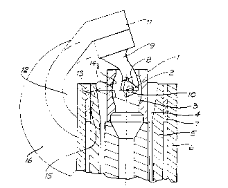
Figure 1 shows sleeve 1 in its relation to cutting
tool 2 at the instant of its mid-position during its last
return stroke, that is after completing cutting of the
last slot 3 in sleeve 1. Sleeve 1 is secured in work
holding chuck 4 contained in work holding spindle 5, in
turn rotatably journalled within axially sliding work
spindle carrier 6 by bearing 7.
Cutting tool 2 is of the triangular throw-away insert
type, and is appropriately housed in a precise pocket or
- recess 8 in tool holder 9 by retaining screw 10. Tool
holder 9 is secured to cutting head 11 of cutting spindle
12 which angularly oscillates about axis 13, through an
angle indicated by the chain-dotted lines 14. Axis 13 in
fact is not a fixed axis but itself angularly oscillates
W092/09394 2 0 9 6 6 4 ~ 8 - PCT/AU91/00500 `~-
about axis 15 of cutting spindle carrier 16 to enable
infeeding of the cutting tool during cutting of a given
slot. The detailed mechanics of this machine will be
described in further detail later.
According to the disclosure in US Patent 4,154,145
unloading of the sleeve after completion of slotting is
accomplished by removal of a stop (shown as item 41 in
Figure 2 of that patent) and rotation of the cutting
spindle carrier (shown as item 9) through an angle of
approximately 90 degrees clockwise from the position
shown, causing the cutting tool to retract upwards and
rightwards in a complex path determined by the kinematics
of the mechanism. This is only possible when the
disposition of the axis of cutting spindle (shown as item
8) relative to the axis of the cutting spindle carrier
(shown as item 10) forms a line inclined at approximately
50 degrees to the horizontal, as shown in Figure 3 of that
specification. Even so, a finger like cutting tool as
shown in this figure must be used in order to avoid
interference between the cutting tool and the sleeve
during retraction, precluding the use of a practical
throw-away cutting tool insert or the use of an optimum
load path.
Now referring to Figure 2 of this specification. If
the nearly vertical disposition of the line joining axes
15 and 13 were used to improve the cutting geometry as
described above, and if the cutting tool reciprocation
were stopped at the position shown and tool holder 9 and
cutting tool 2 retracted in direction 17 according to the
methodology disclosed in US Patent 4,154,145, an
interference with corner 18 of the bore of sleeve 1 would
occur to the extent indicated by dotted line 19, making
the use of a practical throw-away cutting insert
impossible. On the other hand, according to the present
invention, whilst the cutting tool continues to
209664~
~92/09394 PCT/AU91/00500
reciprocate, sliding work spindle carrier 6 is caused to
descend in direction 20, carrying sleeve 1 axially clear
of cutting tool 2 so that the envelope of its movement
lies entirely within the confines of the cylindrical bore
of sleeve 1 and therefore avoids any such interference.
Referring now to Figure 3, which shows a general
arrangement of a slotting machine conforming to the
present invention, the operation of the cutting mechanism
is similar in certain aspects to that shown in US Patent
4,154,145. Cutting spindle 12 is arranged to oscillate
about axis 13 in cutting spindle carrier 16 this, in turn,
being journalled to angularly oscillate about axis 15 in
head stock 21. Note that axis 13 of cutting spindle 12 is
located substantially vertically above axis 15 of cutting
spindle carrier 16 rather than obliquely above. Angular
oscillation of cutting spindle carrier 16 is imparted by
lever 22 and causes axis 13 to move between extreme
positions 13a and 13b (refer to Figure 2) in a manner
which will now be described.
Angular oscillation of cutting spindle 12 is imparted
by lever 23 secured thereto, crank pin 24 and the
connecting rod 25. Typically, cutting spindle 12
oscillates through an angle of about 40 degrees whereas
cutting spindle carrier 16 oscillates through an angle of
about 10 degrees.
Connecting rod 25 is driven by main shaft 26 which
rotates about axis 27 in journals provided on machine
frame 64 and is provided with a "cranked" section as at
crank 28. The offset of crank 28 given by the
displacement between the axes 27 and 29, is such as to
impart the desired angle of oscillation to cutting spindle
12.
Bell crank 30 carries roller followers 31 and 32
which engage cams 33 and 34 respectively, and are urged
into contact therewith by reactions resulting from the
209G64S
W092/09394 PCT/AU91/00500 --
- 10 -
application of a force applied in direction 35 by spring
36. Spring 36 is arranged to act on the extended end of
pin 37, pivotally connecting bell cr-ank 30 and lever 22.
The lower end of spring 36 is anchored to machine frame 64.
Thus bell crank 30 moves in space under the action of
the two cams 33 and 34 whose output is effectively "added"
to impart the required angular oscillation to cutting
spindle carrier 16 via lever 22.
Cam 33 is mounted on main shaft 26 and has a constant
radius about axis 27 for about half its periphery and has
a semi-elliptical section providing a reduced radius over
the other half of its periphery. Cam 33 provides infeed
of cutting tool 2 during the portion of the cutting stroke
when metal is being removed and relief of cutting tool 2
lS during the return portion of the cutting stroke. The
infeed and relief action of cam 33 is more fully described
in US Patent 4,154,145.
Cam 34 is mounted on shaft 38 supported on journals
on machine frame 64 and rotates in the direction shown.
This cam is formed as a spiral scroll over three quarters
of its periphery, with a reduced radius section over the
other quarter, and provides the progressive infeed
necessary over a series of cutting strokes to fully
machine a given slot 3 in sleeve 1.
This infeeding action of cam 34 is more fully
described in US Patent 4,154,145. In the position shown,
cam 34 had just caused roller follower 32 to rise to the
top of its travel, corresponding to the maximum cutting
depth of cutting tool 2, and descend therefrom to the rest
at the abovementioned reduced radius section. When roller
follower 32 contacts cam 34 at this reduced radius
section, the infeed position of cutting tool 2 corresponds
to that shown in Figure 1.
Cam 34 is driven by reduction gearing 39 from main
shaft 26 by pinion 39a which rotates in the same direction
20966~5
,/092/09394 PCT/AU91/00500
as shaft 38. Main shaft 26 rotates continuously under the
action of motor 40 and driving belt and pulley 41.
Shaft 38 carries sprocket 42 which drives through
chain 43, sprocket 44 and thence, via universally jointed
shaft 45 index mechanism 46. This index mechanism is of
conventional form and serves to rotationally index sleeve
1 for the cutting of successive slots.
Pinion 39a is journalled on, but axially constrained
with respect to main shaft 26. Pinion 39a has dog clutch
teeth formed on the near face thereof, and pinion 47 is
similarly journalled and constrained, but has dog clutch
teeth formed on the far face thereof. Clutch member 48 is
slideably keyed to main shaft 26 and is axially shifted
along main shaft 26 by yoke 49, and has dog clutch teeth
formed at each end thereof. Yoke 49 is carried on shaft
50 which is caused to slide axially through the action of
follower 51 and lobed cam 52 rotated by worm gearing 53
from main shaft 26.
In the position shown in Figure 3, clutch member 48
had just completed an axial shift in the direction shown
by arrow 54 through the action of lobe cam 52 so
disengaging clutch member 48 from pinion 39a and engaging
it with pinion 47, whereupon cam 34 and index mechanism 46
stop rotating, and cutting tool 2 continues to execute the
path shown in Figure 1 clear of the bore of sleeve 1.
The loading cycle of the machine is now ready to
commence. Pinion 47, through reduction gearing 55 and
sprockets 56 and 57 and chain 58 now drives shaft 59 and
rise and fall cam 60 in the direction shown.
Cam follower 61 is journalled in lever 62 which is
pivoted about axis 63 in machine frame 64. Lever 62 is
extended to form a yoke having rollers 65 engaging a
groove 66 in sliding work spindle carrier 6, slideably
journalled in machine frame 64 in bearing 67 at its lower
end and bearing 68 at its upper end (see also Figure 4).
W092/09394 2 0 9 S 6 ~ j PCT/AU91/OOSOO
- 12 -
Sliding work spindle carrier 6 incorporates a conical
face 69 which, at the instant shown, is forced upwardly
into conical recess 70 in bearing 68 through the action of
lever 62, cam 60 and cam follower 61. Immediately upon
the loading cycle commencing, cam 60 rotates in the
direction shown and the cut-away section 71 of cam 60
allows sliding work spindle carrier 6 to commence to
descend. At the same instant shaft 59 drives, through
bevel gears 72, shaft 73 leading to loading device 74 in
which is journalled, both slideably and rotatably, shaft
75 carrying at its lower end loader arms 76.
Loader arms 76 are equipped with grippers 77 which
are actuated to open and close upon sleeve 1 held in work
holding chuck 4 and upon the next sleeve to be machined la
supported on loading station comprising platform 78 which
forms a protrusion on integral extension 79 of sliding
work spindle carrier 6.
The mechanism within the loading device 74 comprises
conventional machine elements which cause, upon rotation
of shaft 73, the axial sliding and successive half-turn
rotations of shaft 75, and the opening and closing of
grippers 77 in the appropriate sequence now described.
In the position shown in Figure 4 grippers 77 are
open both during the machining of the slots in sleeve 1
and during the loading of the next sleeve to be machined
la on loading platform 78.
As the loading cycle commences grippers 77 close on
sleeves 1 and la, and shaft 75 and sliding work spindle
carrier 6 descend in the direction shown in a co-ordinated
manner driven respectively by an appropriate cam in
loading device 74 (not shown) and cam 60. A short time
interval thereafter lever 80 carrying roller 81 engages
abutment 82 on machine frame 64 in such a manner as to
raise work holding chuck 4 in its conical location in work
holding spindle 5 so releasing sleeve 1, such method of
209~6~5
~092/09394 PCT/AU91/00500
release being common practice in the operation of lathe
collets.
Figure 5 shows the instant when the work holding
chuck 4 is open and shaft 75 is arrested in its downward
movement while sliding work spindle carrier 6 continues to
descend, so removing sleeve 1 from work holding chuck 4 as
illustrated in Figure 6, whereupon shaft 75 and loader
arms 76 are rotated one half turn in order to bring
unmachined sleeve la above work holding chuck 4 and
finished machined sleeve 1 above loading platform 78. The
sequence of events just described is now performed in
reverse order so that sleeve la is inserted in work
holding chuck 4 and is ready to be machined, and completed
sleeve 1 is likewise place on loading platform 78 and may
be removed by hand, or by a suitable robot device, to an
adjacent conveyor (not illustrated).
During the entire loading operation described, which
occupies 2 or 3 seconds, the cutting spindle 12 continues
to reciprocate whereas cam 34 and index mechanism 46 are
temporarily disabled through the disengagement of clutch
member 48 with pinion 39a. Immediately thereafter further
rotation of lobed cam 52 causes the loading cycle to be
arrested, and clutch member 48 again engages reduction
gearing 39 so as to recommence the cutting cycle.
It will be appreciated by persons skilled in the art
that numerous variations and/or modifications may be made
to the invention as shown in the specific embodiments
without departing from the spirit or scope of the
invention as broadly described. The present embodiments
are, therefore, to be considered in all respects as
illustrative and not restrictive.