Note: Descriptions are shown in the official language in which they were submitted.
W092/ln79~ PCT/EP91/023~
_ --1
2096727
P~OTOGRA~IC P~O OE SSING ~PPARAT~S
This invention relates to photographic
processing apparatus and is more particularly,
although not exclusively, concerned with the
application of photographic processing solutions
to the material to be pxocessed.
Processing solutions have been applied
to photographic materials using various methods.
One method has been to use a high speed moving
surface. It has been known to use high speed
spinning drums to provide the high speed moving
surface. In these arrangements, processing
solution is retained in a tray through which the
high speed moving surface passes. As the surface
passes through the tray, it lifts processing
solution out of the tray and carries it to a
position where the solution is applied to the
photographic material being processed.
In one arrangement where a high speed
spinning drum is used, a mess blanket is ~sed to
hold the material against the drum surface. The
drum is heated by hot water inside it. In
another arrangement, a moving belt is used to
transport the material across the surface of the
spinning drum.
US-A-3 192 846 discloses an arrangement
in which photographic material is transported
through processing apparatus on fluid layers
formed one either side of the material. These
fluid layers act as bearings for the material to
prevent it becoming damaged during
transportation. The fluid layers are applied by
conduits positioned on either side of the
material. The material is driven through the
processing chamber by drive rollers positioned at
.. . . . . . ..... .. . . .
.. . . .
WO9~tl~790 PCT/EP91/023~
2~96~2 ~
either end. Another arrangement is also
described in which rollers are used to guide
material over a moving applicator belt as
described above. ~gitation is achieved when the
linear speed of the applicator belt greatly
exceeds the linear speed o~ the material being
fed through the processing chamber.
In the applicator belt arrangements
decribed above, large ~olumes of processing
solution are required. This means that the -~
processing solutions used need to be s~able for
relatively long periods of time.
In redox amplification processes where
colour materials are developed to produce a
silver image (which may contain only small
amounts o~ silver) and then treated with a redox
amplifying solution to form a dye image, the
amplifying solution contains both an oxidising
~ agent and a reducing agent and it is therefore
inherently unstable. That is to say, unlike a
conventional colour developer solution, amplifier
solutions will deteriora~e in less than an hour
even if left in a sealed container. The best
reproducibility for such a process has been
obtained by using a "one shot~ system, where the
oxidant is added to the developer and the
solution mixed and used immediately ~or after a
short built in delay) and then discarded. Such a
"one shot" system cannot be used with the
applicator belt arrangements described above as a
relatively large volume of processing solution is
required. Furthermore, the "one shot" system
leads to the maximum solution usage possi~le with
maximum effluent and maximum chemical costs. As
a result the whole system is unattractive
.. . ..
- . - .. . - - -- -
. . ...
- - ,
:
WO 9~/1079û PCr/EP91/02364
_ 3
2~9~727
especially for a minilab environment where
minimum effluent is required. It is believed
that it is these shortcomings that have inhibited
commercial use of this process.
It is therefore an object of the present
invention to provide processing apparatus
incorporating an applicator belt which uses small
amounts of processing solution, and therefore
overcomes the disadvantages mentioned above.
According to one aspect of the present
invention, there is provided photographic
processing apparatus for processing photographic
material comprising an applicator belt for
applying processing solution to the photographic
material characterized in that at least one
transport surface is provided for transporting
the material over the surface of the applicator
belt.
Preferably, the applicator belt lies in
a substantially vertical plane.
Advantageously, a reservoir i5 provided
for storing processing solution. The applicator
belt removes solution from the reservoir for
application to the photographic material as it
moves through the reservoir. The reservoir has a
volume such that replenishment rate of the
processing solution is at least three times the
reservoir volume during the useful life of the
processing solution.
By this arrangement, only a small amount
of processing solution is required. This has the
advantage that unstable processing solutions, for
example those used in redox amplification
processing can be used.
.. . . . .. . . . ..
.. _ .. . . .. . . ..
- . .
.. . . ..
- - : .. ~ . :~
WO92/10790 ` PCT/EP91/023~
~96~ ~4~
It is preferred that ~he at least one
transport surface comprises a surface ¢f a
transport belt which is positioned adjacent the
applicator belt. In the pre~erred embodiment of
the invention, two transport belts are provided
which are positioned one on either side of the
outside surface of the applicator belt. This has
the further advantage in that apparatus according
to the invention can easily be fitted into
standard photographic processing apparatus.
For a better understanding of the
present invention, reference will now be made, by
way of example only, to the accompanying drawing,
the single figure of which shows a schematic
cross-sectional view of an applicator belt
arrangement constructed in accordance with the
invention.
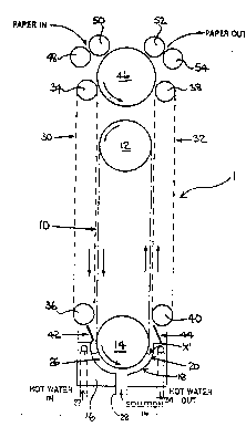
A processor constructed according to the
present invention is illustrated in Figure 1.
The processor compri~es a centrally mounted
applicator belt 10 which is carried by a pair of
rollers 12, 14. At the lower end of the belt 10,
a hollow block 16 is positioned, the upper
surface 18 of the block being shaped to define a
reservoir 20.
The reservoir 20 is heated by hot water,
the hot water flowing into and out of the block
16 at 22 and 24 respectively. Processing
solution 26 is maintained at a predetermined
level within the reservoir 20 as indicated by
arrow 'X', and is added to and removed from the
reservoir 20 by inlet/outlet 28.
The lower roller 14 dips into the
reservoir 20 and processing solution 26 is picked
up and carried round by the applicator belt 10.
.
-- - .. . . .. . . . .
.. - _ - ~ - . . .
. .
.
,
.
WO92/10790 PCT/EP91/023
--5--
2~96727
A transport belt 30, 32 is mounted on
each side of the applicator belt 10 as shown.
Each belt 30, 32 is carried by a pair of
vertically spaced rollers 34, 36, 38, 40. The
lower rollers 36, 40 are positioned adjacent the
reservoir 20. Guides 42, 44 are provided at the
lower ends of the transport belts 30, 32 to
direct the photographic paper to be processed
into and out of the reservoir ~0.
A central roller 46, positioned above
the upper roller 12, helps to guide the paper
into and out o~ the processor 1 in conjunction
with inlet guide rollers 48, 50 and outlet guide
rollers 52, 54.
In use, processing solution 26 is added
to the reservoir 20 through the inlet/outlet 28.
Photographic material, for example paper, is fed
into the processor 1 through inlet rollers 48,
50. The paper is then directed, by roller 46 and
~ransport belt 30 in to the space between the
applicator belt 10 and transport belt 30 itself.
The transport belt 30 holds the paper against the
applicator belt 10 and drives it through the
processor 1 in a downward direction until guide
42 is reached.
Here, the paper is directed into the
processing solution 26 retained in the reservoir
20 by the guide 42. The surface 18 of the block
16 defining the reservoir 20 guides the paper
through the processing solution 26 around roller
14 and that portion of the applicator belt 10
adjacent the roller at that instant towards guide
44. The paper is then directed upwards into the
space between the applicator belt 10 and the
other transport belt 32. The belt 32, like belt
.. . .. ....... ..... .. . .. . . . . .
- - - ,
- -- - - , - . :
- . : , ~ -.: :: ~ , ,
WO9~/1079~ PCT/EP91/023
~6~?~ -6-
30, holds the paper against the applicator belt
10 and drives it upwards away from the reservoir
20 towards the roller 46. Roller 46 directs the
paper through outlet rollers 52, 54 to the next
stage in the processing apparatus. - ~
In the processor shown in the drawing, r
the paper being processed is retained on the
transport belts 30, 32 by means of suction. This
means that the paper is travelling at the same
linear speed as the transport belts 30, 32. The
applicator belt 10 has a much higher linear speed
and carries a layer of processing solution on its
outside surface.
The paper surface being processed is
maintained in contact with the liquid layer, and
ayitation of the surface is provided by shear
produced across this liquid layer due to the
difference in linear speed between the applicator
belt 10 and the transport belts 30, 32.
The transport belts 30, 32 have linear
--1
speeds of approximat21y 25mms , whilst the
applicator belt 10 has a linear speed in the
range of 0.15 to 1.02ms 1 (30 to 200ftmin 1).
As only a small volume of processing
solution 26 is contained in the reservoir 20, the
turnover of prescessing solution can be very
short, for example less than 10 minutes. This
means that equilibrium can be approached in 30
minutes, and in this example the solution
stability of the unreplenished working developer
gave acceptable sensitometry over a period of 30
minutes. The reservoir 20 retains a volume of
processing solution between 100 and l50ml prior
to start up of the applicator belt 10.
Naturally, as the belt 10 moves processing
. .
--
- . ,
WO92/10790 PCT/EP91/023
--7--
2~96727
solution is xemoved from the reservoir 20 and
applied to the material being processed.
As only low volumes of processing
solution are used in the processor, only small
volumes of solution need to be discarded if the
processor is stopped for any reason, for example
cleaning. This reduces the effluent produced.
It is preferred that theiapplicator belt
10 has a patterned surface to assist in the take-
up of processing solutlon from the reservoir 20.The patterned surface also assists in the
provision of agitation to the paper surface.
As the processor is arranged
substantially vertically, it can easily be fi~ted
into standard processing apparatus, for example,
a Noritsu 801 or Kodak system 25 processor.
Although the invention has been
described with reference to the processing of
photographic paper, it is not limited to such use
o~ly.
Furthermore, the processor according to
- t~e present invention is n~t limited to use for
processing material in a continuous web, but
could equally well b~ used for sheets of
material.
The processor according to the invention
can be used in any environment where good
agitation is required.
In the embodiment described, the
emulsion surface of the paper is innermos~.
Howe~er, it may be desirable that the emulsion
surface is outermost. In such a case, the two
outer belts 30, 32 are now high speed applicator
belts, and the inner belt 10 is a transport belt.
Reservoir 20 is then replaced by a simple
.
. . .
. ... - - -- .
.. , , , _ .
WO92/10790 PCl`/EP9t/023~
~Q9~ 8-
turnaround system comprising a single roller and
two guide members whlch convey the paper from a r
position adjacent roller 36 to a position
adjacent roller 40. Two reser~oirs, each one
mounted below a respective one of rollers 36, 40,
are also provided to supply processing solution
to each one of the two applicator belts. These
reservoirs may be elther ~ntirely separate or
~luidly connected to one another.
.. .... .. . . ........................ . . .
.. . . .
;- ~ ', :.'
- : : ~'..... .